Sorensen DCS Series - Modification and Repair Thread

Wow...
So going over that section (ending about 13:50) we can pretty much figure out what is going on in our supply:

* Big square Filter Cap
* Common mode Choke
* Two small caps, each side down to common earth

Repeat

* Big square Filter Cap
* Common mode Choke
* Two small filter caps to ground

... then off the board as a pair of heavy wires (heavy enough to run 120V at double the 240V current)
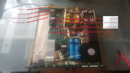
InputFilterSection01.jpg

...

See?
A little patience
A little clever searching (really just referencing the RIGHT SOURCE)
And a solid 10% of our reverse engineering... IS DONE.

Hollywood is total BULLSHIT.
In real life... nobody is a super hero
Everybody is weak and flawed
... (except Elon :) )

A real life Reverse Engineer has to earn it... so if you want to "be one" - this is part of it.
Before you get here, what you want is a solid education - a piece of paper - from the best school you can get into. That will lay the groundwork for you to piece together the puzzle.

Pieces of the puzzle?

Well... like knowing that running capacitors in series WILL double your working voltage (1st order), WILL halve your working capacitance (like resistors in parallel - same formula) - (1st order) ... but second order... we are not guaranteed an equal split of voltage ... and we know that ohms law dictates that voltages in parallel must be equal... so...

(from the video - if you are not tracking me)

We see that we can add a basic voltage divider in parallel with the stacked caps to help urge them to evenly split the load.

SWEET -> Been doing this 18 years and thats the first I have seen it put so simply - on a working product.
(yea - seen a lot of theory - but this is the real deal! Value Engineered, highly reliable, variable power supply.

....

So why so much noise filtering?

Its not (I am guessing...) to keep noise out
Its to keep the noise IN

.. Likely due to regulations around the amount of noise that a product is allowed to barf back into Mains and Radiate into other components - RIGHT?

(yep - UL Certification sort of stuff)

Anything to do with safety?
(Nope - will work just fine without that crap... So short it out if you have to and see :x )

Where is the fusing?
Strangely the fusing (re-settable breaker ) is down stream at the front panel. I guess the 2 flavors of caps and 1 flavor of choke are robust enough that we can rely on the AC Mains Breaker to terminate a dump before fire starts.

-methods
 
Ok -

So based on that...

and

Based on my earlier guess about the problem being on the AC side...
(with the chance it was hooked up to an incorrect mains voltage)

I will venture the guess that perhaps there is a problem with...
eh... (we are thinking heat sunk parts here)

Maybe half of the full bridge rectifier smoked out???

That would TOTALLY develop the kind of behavior I am seeing.
It produced the full DC voltage
It produces the full DC current
(I know nothing of how clean they are... cuz I dont have a scope...)

It has trouble producing full power (pointing us elsewhere... BUT)

It produces LESS than full DC voltage with a 120V input
It produces FULL DC voltage with a 240V DC input
...

Full current on both...

The dials and controls seem to work
No weird buzzing
I only let a LITTLE BIT of smoke out (when I applied 240V while on the 120V setting - a test we WILL repeat and I am pretty sure it came from a TO-220 standing up... but we will see)

Yea
How would we confirm that?

Well... a good quality DMM COULD do it
We expect the output of the full bridge rectifier to follow the following:

240V RMS in (or is that PEAK TO PEAK ??? IMPORTANT)
.
.

(Thank you Google... for indexing the worlds resources... as when I was a kid...)

I HAD A frocking MOLDY AND INCOMPLETE ENCYCLOPEDIA SET FROM 1979 THAT WE GOT FROM A RETARDED GUY IN A TRAILER PARK - AND MY MOM WAS HAMMERED 24/7 - AND MY DAD WAS BUSY HUSTLING

So... thank you GOOGLE for providing resources which DID NOT EXIST previously
(it is so very frocking important <more important that not saying frock> to express to these kids how DIFFERENT reality is now)
and...
To express that there are things that we do to ENSURE that reality does not regress back into what it WAS
AS IT HAS
Historically when countries start behaving like OUR country (the US) is currently
With our ASS HAT leader... swinging is stinking cock around... flaunting weapons of mass destruction... gambling with my sons future.

... ya see...

This is how (in the old days...) you would catch an ASS WHUP'N :evil:
(Being a stove-pipe-douche-bag-know-nothing-rich-kid-punk-lucky-frock)

grrr... ok...
Time to switch gears and head down to the beach.

I cant drill holes in Donald's forehead (or even threaten to... under threat of certain death and/or incarceration) ... so my option is to tuck my little tail between my legs, bark a little, and go frock the sand at the beach.

...
STAND UP AND SPEAK... if you have got something to say about the way the country is being run!
...

DO NOT
I repeat DO NOT
Wait for some sold out, washed up, compromised, self-centered politician ... to put their neck out... up against an insane billionaire... to do your speaking for you.

ya see... they have something to lose...

grumble grumble

-methods
 
Oh yea -

Forgot to say that with the scope we could look for the expected output...

Even with all that filter you will see the bi-polar AC waveform rectified into a positive going (or possibly negative going...) full bridge output (hump, hump, hump) - with the humps not quite touching ground - depending on the filtering (I see big caps up ahead)

sigh...
Guy at GrayBears (our recycling/upcycling spot) laid a bad trip on me this morning... world coming apart at the seams sort of deal... Likely because he was having to throw away a bunch of good stuff (weight limit on his pod) and move out of town - presumably for finical reasons.

Listen to old guys... with bushy eyebrows and hair in their ears *

And... MOST IMPORTANTLY>>>

Not just old RICH GUYS
They are the guys who sold our your future for their own gains
They have PLENTY now... and they see no reason to rock the boat

...

Talk to the old guys who have to live in their car, eat garbage out of dumpsters, shit in the bushes...
Thats where you get the rest of the story.
Their truth (which you need to filter... of course... we all make our own decisions...)

but I am of the opinion that we are not NEARLY as civilized as we envision ourselves to be.

Its like... what... 5 years it would take us to completely mechanize our resource system???
Certainly wont happen as long as we let the business douche bags keep using slave labor over seas... now will it?

WHO is going to invest in EXPENSIVE robotics and EVEN MORE EXPENSIVE ENGINEERS TO WORK ON THEM...
When we can just enslave those who are trapped in communist and corrupt countries?

(You understand this is real right? Do we need to send you on some travel???)

I have touched it first hand.
About to touch it some more.
Ugly shit.

... Now off to the beach I go
With my ol' lady
... and if she is nice... I can sneak peaks at all the young half naked people :shock:
(no desire to touch... only to look :p )

Keep it real or beat it is what I tell folks. :idea:

-methods
 
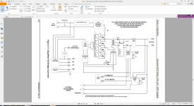
Looking at the high level overview in the Theory of Operation

TopLevel.png

We identified the AC input at the rear left

Not included here we identified the input filtering.
From there it leaves the board on wires - going to the DPST switch shown
Those switches come back to the board - labeled SN and SL (Line and Neutral)

They enter the board very close to 20A Fuse F1 - which is a slow blow 250V
1kw/250V = 4A
1kw/125V = 8A
So the fuse is strictly protecting the wire gauge, switch rating, upstream PCB traces, input filtering, and input connection point

...

From the primary input fuse it goes directly into the Voltage Selector P1 via inrush
We enter on the center two pins, 2 and 3 (one via inrush)

Inrush:
Diagram denotes Power Resistor R116
Unmarked but between the entry point and inrush resistor is a Relay - presuming that is the mentioned K1
(one of the few unmarked parts on the PCB)

(So Wires come in, thru R116 inrush, into transformer - and - obviously onward to high power section)

Assuming relay starts open then closes either on a timer or based on feedbck
1/2A Fuse F2 is tied to R116 on one end, other end reads 40 ohms


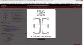
P1 Transformer:

Transformer.jpg

Here we need to be very careful has we have multiple pinouts out of order:

1) Transformer pinout
2) PCB Pinout for that
3) P1 pinout
(With access to PCB easy ringout - for now just looking at top of PCB and using logic)

Its a 2 layer PCB (assumption) so we assume they did not cross traces

Transformer is wired, back to font, as installed as

1
2
4
3

P1 is wired, as installed
4
3
2
1


With the jumper set to HV we get a single loop shorting pins 1 and 4, which would be transformer 1 and 3
With the jumper set to LV we get 1 shorted to 3, 2 shorted to 4, which would be transformer 2,3 and 1,4

(need to investigate that)

Transformer LP-16-700
oh - doh...
https://www.digikey.com/product-detail/en/signal-transformer/LP-16-700/595-1320-ND/1020882

So... I thought the main power was being either passed thru or voltage doubled.
This transformer has either an 8V or 16V output - based on parallel or series config.
It quite small (much smaller that would be needed to handle a KW...)
and feeds into a low voltage section of the board that produces 6.2v, +5V, -5V, 12V, and AUX voltage

SO - Thats a good place to look for smoke replacement if we ran 240V into 120V selector.
Highly probable that some part of that circuit smoked out - maybe we are missing some bias voltage or another... rendering the supply semi-functional.

...

So the 240V Option puts the transformer in Series
The 120V Option puts the transformer in Parallel
That makes sense

Both the input and output are configurable - we will assume the output is set to Series (Check in a minute)
(Rational - I see what look like linear regulators at the output, all of the voltages listed can be created from 16V)

NOTE: Should the input be set to 120V while applying 240V we would produce a 32V output

32V across just about any old school linear regulator would produce too much waste heat
Two standing regulators with heat sinks...

K - next step is to plug in Pjumper
Power the board
Measure the low voltage section for functionality

-methods
 
So the Transformer is rated for about 12W

It is not captive so would be directly connected to input...? but its not - its connected thru inrush fused at 1/2A
There is capacitance on the other end of the transformer - so if we pretend it is not there - I guess inrush makes sense.

Inrush rated at 1/2A - so 60W to 120W total power - but on the resistor - we get current square losses
(assuming fuse protects resistor)

So: 12W transformer

... STOP ...
3 corrections to above

P1 is not wired without crossover

P1-4 ties to Transformer input 2
P1-3 ties to Transformer input 1

P1-2 ties to Transformer input 4
P1-1 ties to Transformer input 3

So - rewinding (where we had a correct answer for the incorrect reason)

Shorting P1-4 to P1-1 would in turn short Transformer inputs 2 and 3
Putting it into series - same answer for correct reason

Transformer inputs ohm out at 60ohms and 130ohms
(Strange - I would think they would be the same... but transformers were before my time...)

In series we get about 200ohms
(btw... no hard shorts on the PCB, jumper select only)

WITH the inrush resistor inline... we would have a 240ohm load on our input AC
1A @ 240ohms = 240W (off by an order so obviously wrong in analysis)

240V/240ohms would give us an amp load thru a 1/2 amp slow blow fuse (sigh - also makes little sense)

Configured in parallel we have 130||60 = ~40 ohms
120V/40ohms = 3A

1/2A fuse is to protect inrush resistor
It looks like 5W or 10W max max or so...
40 * 0.5^2 = 10W

... sigh ...
Need to understand input loading

Transformer output can be up to 16V @ 700mA
Yea - looks like about 12W

12W/240V = 50mA
240V/50mA = 4.8K

... er... how does that work?

eh... at time zero... the current thru the transformer will be near zero
It does not want to change

At time stable current thru the transformer will be maximum.. eh...
(Even Electrical Engineers search Google)

"calculating transformer input current"
(as maybe there is some reluctance inline with our coil resistance eh?)

https://sciencing.com/calculate-transformer-primary-current-7174887.html

AH HA - IMPORTANT POINT
INDUCTIVE MAGIC YES???

So we divide transformer power by input voltage to get input current
12W/240V = 50mA
50mA ^2 * 200 ohm input = 1/2watt lost on its input

Same 50mA running thru the inrush resistor... so...
A tiny amount developed there

Sigh... Multiple things are happening in parallel...

But Stop
Why is it that the restive load of the transformer winding input does not calculate out using ohms law?

Guess?
Pushback from iron coupling into secondary
Lets prove that
...

eh... GOOGLE...
"why does transformer input not obey ohm's law"

... eh.... bunch of crap there ... you can think of it in several ways

1) Just think of transformer as power, divide input voltage

... eh... new search

"why does transformer input winding resistance not obey ohm's law"

About to read this:
https://electronics.stackexchange.com/questions/104087/why-dont-ac-transformers-burn-up

Predicting:
DC Voltage applied... of course ohms law... smoke show
AC Voltage applied... we get?

...

...

AH HA
FORUMS TO THE RESCUE>>>>>>


Would ya look at that shit?
Read the first line... and you will know you are on to the TRUE AND CORRECT ANSWER


Andy gave you the classic academic answer to your questions. Everything he stated is accurate, but I doubt as a beginner you will understand most of it. So, let me take a try at a simple explanation.

Yep
The Story of the Internet Age

43,000 assholes willing to give you an answer that not even THEY understand in practical use...
One old guy with hair growing out of his ears - willing to explain it in semi-laymans terms

NICE

-methods
 
So taking that redirection and digging into my AC background (over 20 years ago now...)

For DC analysis is simple
For AC we must introduce: Frequency, bipolar, and coupling

Our simple R now turns into: R, XL, and XC

When I learned it, it was:
Resistance
Reluctance
Reactance

Remembered as ... "a capacitor reactors and an inductor is reluctant to change"

If memory serves
On a graph
We do Positive X axis, 0 on Y axis, is our resistance
Reactance (capacitive resistance) goes up on Y
Reluctance (inductive resistance) goes down on Y

Where Capacitive Resistance goes DOWN with Frequency going UP
Where Inductive Resistance goes DOWN with Frequency going DOWN
Where that is proven with Bounds of DC and Infinite

DC into Inductive load, XL == 0ohms
DC into Capacitive load converges on infinite ohms
Ok...

Lets check our memory against Google to make sure we are not tarded:


View attachment 1

AH - had it backwards
L goes up, C goes down

I have cracked thousands of those formulas...
Polar notation
X,Y notation
All on a reverse polish notation calculator (You remember those???)

... coming back....

So... lets go ahead and crunch all the math so the loud-mouths dont spout off trying to say that I am not an Electrical Engineer because tools I have not used in 20 years have become RUSTY (been doing other shit... dawg...)

So
What do we have to work with?

V = 240VAC
P = 12W
F = 60hz
L = Unknown - my meter is not here
R = 200ohms or 240ohms (why is the inrush inline with this section... sigh... wtf...? Maybe convenience for the fuse?)

Well... we could back-calculate L to an order of magnitude by assuming power P
Yes?
Yea... we can...

12W/240V = 50mA
50mA * 200ohms = 10V (because the R is still in the circuit...)
That leaves us with effectively ALL of our input voltage developed over a reluctance

230V / 50mA = 4.6K

So now we have to apply formulas involving freqency
Search Google for "Reactance Calculator" (as reactance is much more common of a term)
https://www.electronics2000.co.uk/calc/reactance-calculator.php

Reactance.jpg

We see from above: XL = 2 * pi * f * L, where L is the inductance in Henrys

Using Algebra
XL/(2*3.14*60) = L
4.6k/(2*3.14*60) = L
4600/377 = 12.2

(Sigh... always makes me nervous when previous numbers pop out... but... 12 henry

OK?
Is 12 Henry a sane estimate of a 12W transformer hooked up to 240 mains?
(Easy to answer that today, was very hard 20 years ago)

-methods
 
And of course...
In Electrical Engineering...
There is no such thing as a straight answer!

(Because the output winding affects the input behavior)

Complication.jpg

So
As an aside...
This is the sort of Depth issue that I was ranting about a few weeks back on my blog. It is frocking FRUSTRATING when a clown asks me to just... "Sum it up"... like... in an Elevator pitch.

THIS SHIT DOES NOT SUM UP INTO A TIDY PARAGRAPH THAT YOU CAN UNDERSTAND
WITHOUT ANY BACKGROUND IN THIS
IN ANY WAY, SHAPE, or FORM

Grr......

So right now... we are speaking to Engineers and students on their way to being engineers
Maybe really good teks - with training in the armed forces.

Onward

...

So..
Our simple calculation MAY or MAY NOT have come out correct.

The method I used would be correct if it was an INDUCTOR
(which it is...)

But its an inductor wrapped around iron that has another inductor wrapped around it
Lol :lol:

So...
In school...
They teach you, at this point, to just reference formulas

YES - we had to prove each and every one of those bastard formulas for ourselves... but once proven... they are just USED

I dont like doing that
I like to prove it from as root as possible every time

Onward... (and how off track are we?)
LOL

... This same sort of "layer after layer after layer" is how I attempt to describe the "reality of reality" to knuckle heads

Of course
They bark off with some CNN of FOX bullshit (or maybe some NPR bullshit)

With the (completely incorrect) ASSUMPTION that any subject can be understood or discussed with a BLURBS worth of information.
Right...

Like... we can actually have a meaningful discussion starting from what you learned on FOX. :roll:

"Meaningless question Friend... meaningless question" - Tom Robbins

-methods
 
To pause here - this is where we are at:

Troubleshooting a DCS 60-18
- Reverse engineering from the AC in
-- We hit the transformer that feeds the low voltage DC regulators
--- We are trying to prove out the Voltage, Current, Resistance, and Reluctance of that transformer

So....

.... That we can understand the value of 500mA selected for the secondary Fuse

Totally Off Track
And Totally On Track

Not really here to fix a supply
I am here to:

1) Reverse Engineer It
2) Show aspiring Engineers that... yea... its all ugly... nothing solves clean
3) Refresh on all of the skills I have learned over the last 20 years
4) Familiarize with every component on the board - should I need them - for later design :!:
5) Burn off nervous energy... keep it real... offset the tendency for the internet to make things look easy

meh...
Stuff like that.

I have a 6yo over here staring at me like I am retarded
A 36 year old just finishing up her homework
And - an adventure ahead

-methods
 
Ok - back on this for an hour

I think I may plug a few things back in and just fire it up in 120V mode
Doing that now
Should you hear any fire engines....


-methods
 
The DC section checks out - all voltages present

Only a couple were spot on - but no indication that miss-wiring of the step-down blew out any of the regulators.
I tested it at 0V output and max output (unloaded)

...

Moving on to the rectification stage (dude... I need a scope :? )

-methods
 
With 120VAC RMS coming in...

The Primary caps (big long blue caps) have 150VDC across them (split evenly)
(As read with a TOTAL GARBAGE METER... so INDICATION ONLY)

The heavy 10K divider reads the same (this is the divider that evens out the voltage on the caps - referenced previously)

AC Can be read on the divider -
0V across the stack
50V across each leg

...

Well... without seeing it on a scope... it sure looks like the full bridge output.

Next step would be to load the supply as heavy as possible and see if it holds up.
Going to do that now.

IIRC 420V puts out a couple hundred mA
420V*0.2A=84W
(Less than 1/10th of the rated output)

So - eh - a load capable of holding off the voltage and sinking the heat

420V / 200mA = 2.1K resistor

I have a lot of those at the rated power range but they are at Calfee's

Options:

100W light bulb - You would guess that running 3 or 4 in series would be close to it eh?
100W/120V = 833mA
120V/833ma = 144 ohms
2.1k/144ohms = 15 bulbs (why does that not make sense? - oh yea - it would be 400W for 4 in series)
No good - unless I want to drive it into CC (which may be fine... but I can just short it for that... we want to develop Power not run in CC)

Heater - 1KW
Estimate 1/10th the resistance above
Would need 150 of them :mrgreen:

Ok - what draws about 100W @ 400V?

Things in series - 4 apx
Things in parallel...
Any sort of controller rated to that voltage (into a variable load)

A programmable load is what we want.
One rate for 1KV and 1KW
Lets go see...

Ok back - near impossible to find
You have to just roll your own... or wait for technology to catch up.

Best bet - stacking 240V loads *
(Or just going to pick up my box of resistors - of course - resistors will work)

-Schindler
 
Many AC-DC converters (which of course work as DC-DC converters) can accept up to 350V
These come in wattage ranges which are useful - 10W - 100W
Perhaps I can string some of those in parallel
I have boxes and boxes

If they are rated to 350V we can probably put 400V into them - only smoke will tell

Another option is to run the output at more like 120V or 240V into standard appliances
Yea they expect AC but many dont really know the difference (anything with a bridge on its input)

-methods
 
Rewind

So...
I am not loading the supply currently
And it will not get to the rated output (Where it will if I apply 240VAC)

This points in a different direction
As it rests... something is wrong

Maybe I will just keep investigating up the power chain
If the manual calls out what the chopper should be putting out - we may be able to solve it there.

AT ONE POINT THE FAN DID GO OUT

In front of the fan are 4pcs IRF450 on a really big heat sink
I do see a thermal pickup - but it is on the far end - and it is possible the parts spiked to overheat and the

MOSFET N-CH 500V 12A TO-3-3

Overheated

Eh... they are in parallel I presume?
500V rating is not that high - I had guessed it would chop higher then knock down for the final output

Sigh...
Time to quit speculating and actually read the manual :idea:

(I like to first skim, then guess, then go back and read. Yea I make a lot of mistakes but thats how we learn. If we dont test ourselves... we lie to ourselves... because anybody can watch a Youtube Video, regurgitate the utterings, and understand/know nothing. My intent is to understand - to the level necessary to troubleshoot and modify)

-methods
 
Reading on... the documentation deviates from the hardware.

I am pretty sure C72 and C73 are the filtering around the bridge
1uF of solid and a pile of electrolitic

... Confirmed that the Inrush is controlled by a fixed time (and not feedback) - its an RC Timer that biases a transistor

...

-methods
 
ALARM :shock: :shock:

For 230Vac operation, rectifier CR35 and filter capacitors C32(A,B,C) and C72(A,B,C) are
configured as a full wave bridge. For 115Vac operation the input voltage selector P1 is
configured so that CR35, C32(A,B,C) and C72(A,B,C) form a voltage doubler. In this manner,
the rectified DC voltage is always within the range of 225-350VDC with either a 115 or 230Vac
input voltage. In addition to determining the input rectifier configuration, P1 also configures the
connections to the primary of auxiliary transformer T4 for series or parallel operation.

Lets parse that:

CR35 is the main rectifier - so the main output
We already investigated T4 (jumping to the end)

For 230Vac operation, rectifier CR35 and filter capacitors C32(A,B,C) and C72(A,B,C) are
configured as a full wave bridge. For 115Vac operation the input voltage selector P1 is
configured so that CR35, C32(A,B,C) and C72(A,B,C) form a voltage doubler.

Eh... I am not seeing this. I dont even see how this could happen (yet)

In this manner,
the rectified DC voltage is always within the range of 225-350VDC with either a 115 or 230Vac
input voltage.

Err... NOPE
Not on mine. I am seeing 150VDC... so frocking GREAT... as the next sections of the circuit (after the chopper) look like black magic HELL to me... sigh...


In addition to determining the input rectifier configuration, P1 also configures the
connections to the primary of auxiliary transformer T4 for series or parallel operation.

Yea - we saw this. I can trace that and it makes sense.

So... Eh... Somehow...
Configuring P1 changes the way the full bridge operates
It magically doubles our AC voltage (er - HOW?)
And we have found our first problem:

1) Expect 225V to 350V on the main caps.
See 150V
THO... remember... I am using a $35 AutoZone meter... to "keep it real"
(i.e. if someone is in a remote location or poor country... they should be able to duplicate this effort... yes???)

(In the spirit of Science: Set up an experiment which can be repeated!)

... OK ... to understand how it is that the 120V gets doubled by plugging in the jumper
The PCB DOES flex like crazy in that area - especially why inserting the 1/2 amp fuse.
Perhaps a PCB trace is fractured.
With AC - if one is - we would probably see some flash around it

Its time to pull the PCB out of the housing... (a big step as now we have to deal with heat sink goop and other crap)

-methods
 
Now...

Lets assume the 120V jumper was in and someone applied 240V

If what we read above is true...
Where the power stage expected 240V
It would get 480V

Which... is undoubtedly (in a civilian design)... over the rating of the downstream parts!!!
(Where as in MillSpec they would use whatever parts necessary to make it impossible to break - hence the bulk and expense)

So
Lets look up the rectum fryer and caps around this area where we expect 480V hit a 240V circuit*

-methods
 
I ran an experiment
It does not jive with what I see above

1) Connect the jumper for 240V operation
2) Apply 120V
3) Expect?

well....

If the 240V setting was pass thru
And the 120V setting was doubling
We would expect half?

Yea - seems logical

Result of Experiment: I SEE THE SAME 150V DC

ok

If we trust our documentation (Which so far... is NOT matching our hardware... but... eh...)

OK

At this point I will return to the video and see if watching it further will explain how magically switching P1 doubles the input voltage.

This must be where somebody hosed the design
ohh.... buddy..... :eek:

If we could just find a Fet and maybe some caps that blew out at the first stage after a transformer...
Or a cooked trace...
So stoked

-methods
 
NOTE: That was a NO LOAD test

A no load test has little to nothing to say about a load test*****

Even blown parts can "sorta work" while handling no power
POWER is what pushes a circuit to do work
Work is what it is not doing

I want to get some work out of this thing!

Apparently - they have managed to fit an entire horse into this tiny box
(or at least something which can harness a horse)

-methods

P.S. I grew up riding horses from time to time. They are VERY POWERFUL animals :shock: We rode bareback with a blanket and reigns. I was small at the time and the horses were almost unmanageable (even the old lazy horse)
 
Watched the rest of the video
Nothing to talk about right now.

This is what we need to investigate:

For 115Vac operation the input voltage selector P1 is
configured so that CR35, C32(A,B,C) and C72(A,B,C) form a voltage doubler.

I do not know how a Full Bridge and two sets of caps can double an AC Voltage :?
I also do not see those caps on the board

...

At this point I would be inclined to dig around in documentation to see if the (somewhat rare) 600V flavor is intended to ONLY be used in 240V mode. It would not surprise me a bit if the 300V and down are all similar - and the 600V is a one-off.

Duh know
AC rectifier is AC rectifier is AC rectifier

Down the road a way is where we chop that DC into as high of a voltage as we like
Right?

So... eh... they should all be the same I guess

Dont know -
But finding out :wink:

-methods

K
6yo is climbing all over me telling me that we need to go dig holes in the woods and wait for Banana slugs to come (implying that he has consumed all of the patience he has watching me type at the PC)
 
What is jumper P2 ??????

I see no mention of it anywhere
Its high power like P1
Its right next to the rectifier

Its inside of the primary side - right in the middle of all the business...

...

These supplies are shipped standard for 240V
You can order them set up for 120V

I wonder... if when ordered for 120V... they come with another jumper selected...
Or maybe a different component populated....

...

Dont know
Have set up a lot of the 60V in both configuration and they work

This one is 600V
It looks quite different inside
I have no experience with it - or with much at this voltage range

-methods

(Now it is total mystery... in hours, days, weeks, or months - it will be trivial knowledge. Right?)
 
Jumper P2 has 150VDC across it
(AC reads 3V ripple)
 
With time we could draw one.
I was not planning to dig that deep - but if it is a 2 layer board... it would only take about a thousand hours :)

-methods


P.S. The AC bulb is not lighting up - the one next to the rectifier. It has 120V - bulb is just out.
 
In the tutorial about Rectifiers, we saw that the DC output voltage being controlled by the rectifier is at a value below that of the mains input voltage. The Voltage Multiplier, however, is a special type of diode rectifier circuit which can potentially produce an output voltage many times greater than of the applied input voltage.

https://www.electronics-tutorials.ws/blog/voltage-multiplier-circuit.html


Hmmm...


The Voltage Multiplier is a type of diode rectifier circuit which can produce an output voltage many times greater than of the applied input voltage

for later today

-methods
 
Multiplier circuits like that were pretty common in the days of vacuum tubes. Really impressively dangerous ones were used for large CRTs. But they are not so good for high power applications.
 
Back
Top