thundercamel said:
Thanks for the reply
")
I hadn't heard about different serial connections causing uneven discharging before.
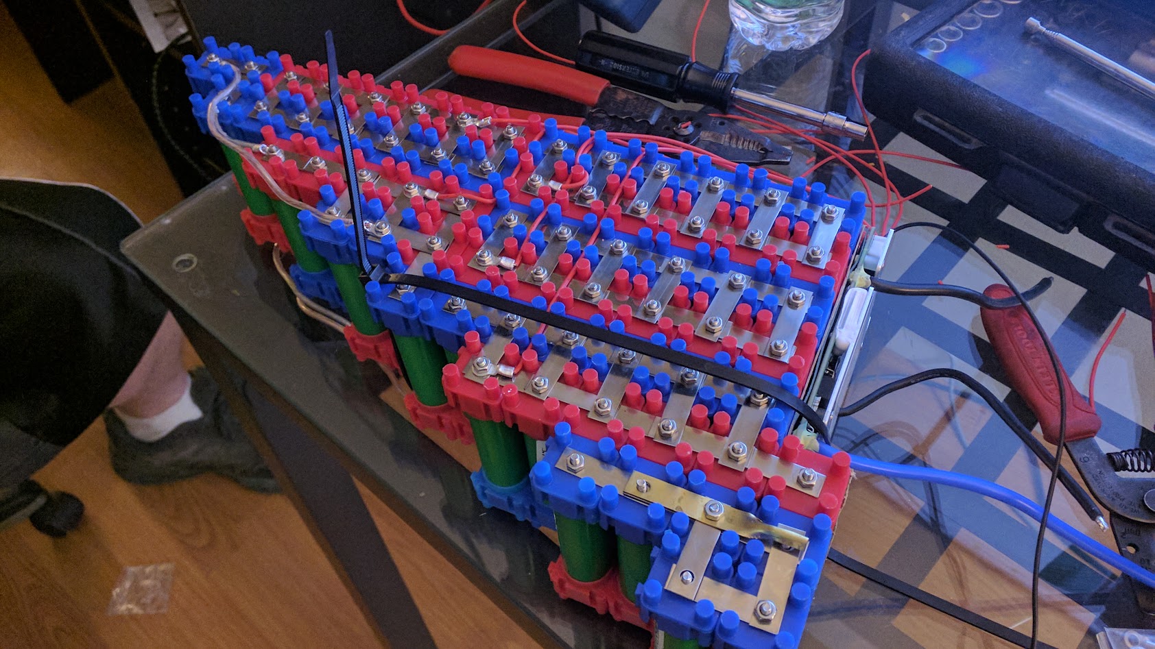
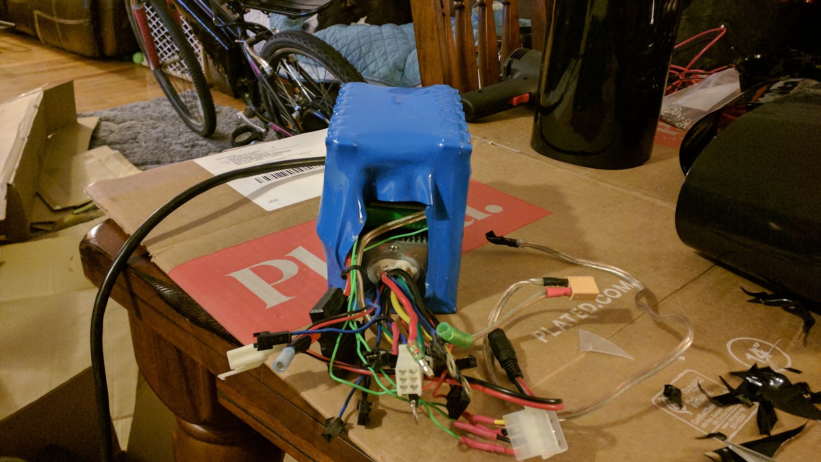
Nice battery build!
Let things work out a few more charge cycles. It may be that the weak group is not really weak. It may be that you actually have a weak cell in there too. Smart BMS allow you to have so much better awareness of your pack status than dumb BMS. It is possible your dumb BMS was NOT doing it's job and you just didn't know it and now you do. Maybe you've had a problem with a weak set of cells all along? give things a few more charge/discharge cycles and see how it goes.
There's 2 things to think about in any pack. They have what I call a recovery voltage and a load voltage.
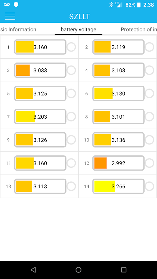
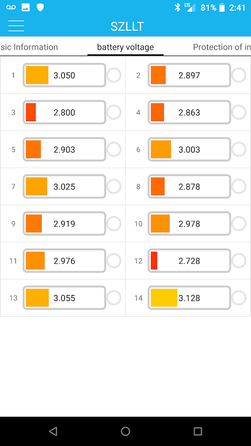
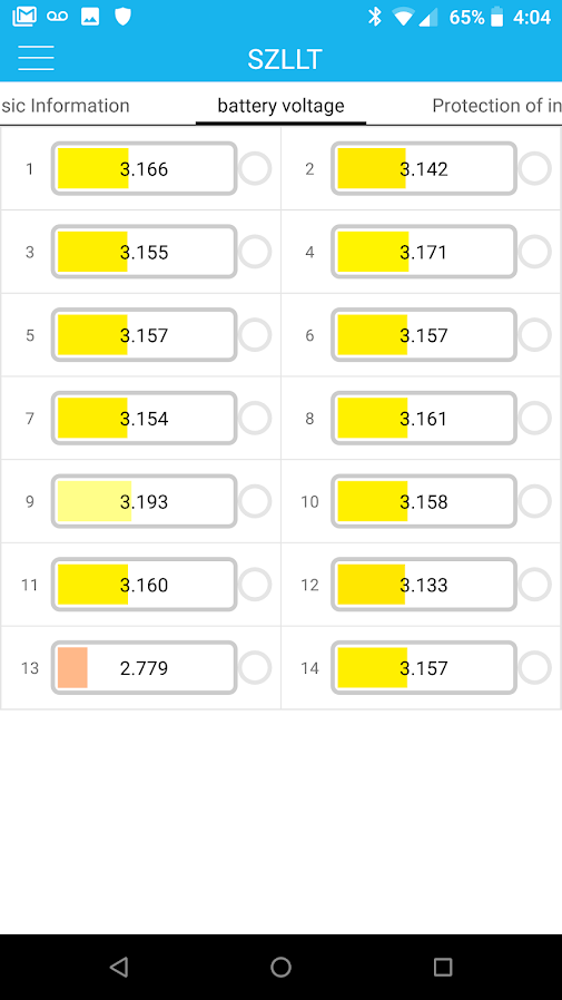
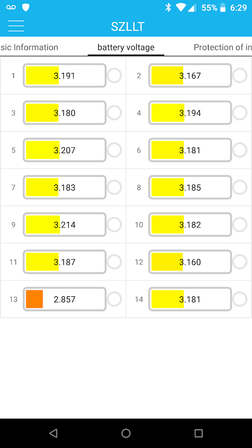
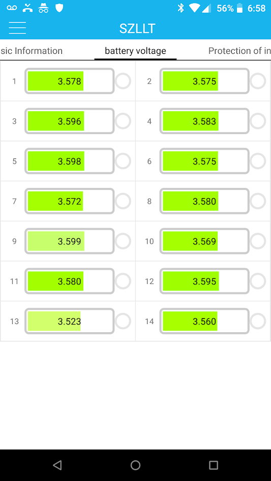
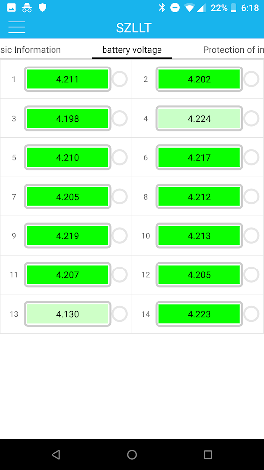
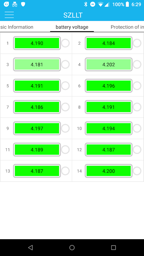
You will commonly see your cells sag to some lower voltage as you load them. I call this load voltage and it's the real voltage of the pack. Then take away the load and you will pack voltage rebound upwards several volts, this is recovery voltage and should be ignored as it isn't anything you can realistically use. Ideally, you want a battery pack that does NOT sag at all, or sags very little, like 1-2% at most. However, towards the bottom of your charge, you will see that sagging gets worse and worse. LEts say your pack fully charged is 48 volts and 36 volts when discharged. At 48 volts, you may see sagging to 47.6 volts. At 37 volts, you may see that under the same load that the pack sags to like 33 volts. This is pretty typical.
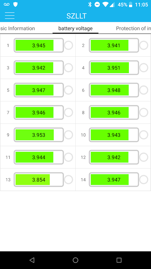
I'm sure you have looked at the last post by Izeman. That's what your pack ought to look like fully charged and fully discharged. Notice how similar his cell voltages are. This is what you want.
IMHO, A pack with a cell that runs down too quickly is only going to get worse and worse. IT is already weak and you need to load it just as much as the other cells around it. It won't hold up long term most likely. You have significantly reduced capacity becasue of a weak link in the chain. To extend the life of those weak cells, the entire pack has to be set up based on those weak cells. It can be used this way, but if you can fix it and eliminate the problem, that's the better solution.
There's a couple of things you can do to help yourself out, if you have weak cells.
1. set the start balance voltage lower. mine are set to 3.9 volts. This gives me more time to balance out the pack.
2. Set the LVC cut-off higher. You know some cells seem weaker than others. Set the BMS with those cells in mind.
3. If the other cells are something like 16Ah and the weak ones are 12ah, then realistically the pack can do 12Ah. Set the BMS to 12Ah.
4. Realistically you can go as low as 2.5 volts per cell on LION. I do NOT recommend this. In fact, I'd set LVC to 3 volts.