First post, electric motorcycle build.

flippy said:
very nice.

are you not going to put anything to insulate the pouches from each other? just to prevent 1 pouch from going "off script" and taking out the entire pack...

some 0.5mil alu plate would do the trick.

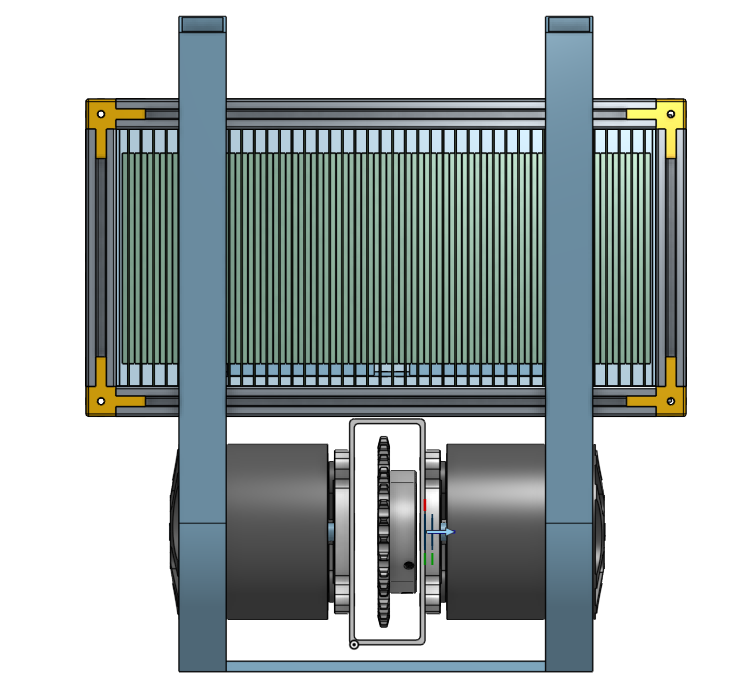
I was thinking about using some aluminum tape between the cells, but honestly between the crazy high ratings on these cells (that I'm only using 2/3 to 3/4 of), along with fairly neurotic monitoring (all cell group voltages, a couple temp probes at various points in the pack, clear battery case), I'm actually not that worried. I didn't bother modeling it (just modeled a .5mm offset), but the cells are going to be stuck together with 3M foam mounting tape.

It looks snug, but they've got plenty of room to expand if things get unhappy, and these don't let go violently. There's a video of somebody dead-shorting one with a current clamp and a thermal camera. 30-ish seconds of 350 amps causes the cell to puff before it reaches like 200 degrees and finally vents out through one of the crimped sides.

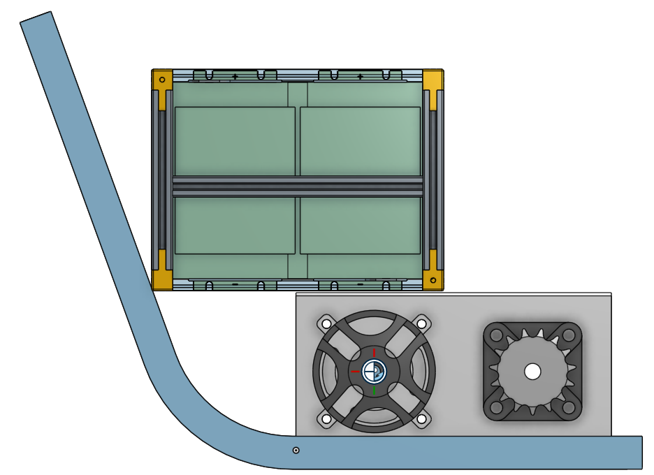
If I put any extra material in place, it would really only need to go in between the two cell stacks. If a cell blows in any other direction, it's either going to hit the aluminum busbar/plate, or the polycarbonate side of the battery box. I was kicking around the idea of cutting a relief into the crimped side so the cell would vent in a known direction if/when it puffs on me.

Also after I took some better measurements off the bike I decided to tip the pack on its side and turn it sideways. Everything fits much more nicely, although it does stick out about 2 - 2.5in outside the frame rails. That would make it bit wider than the radiator, but nothing that I can't compensate for by getting creative with the bodywork.
6lLvW0s.png

Y5sMOA2.png


Sidenote: There's still room to add a few hundred 18650's down the road when I want to add some range.
 
Didn't get to work on my accord because it was pouring, so I spent a couple hours trying to get my non-blown-up controller to talk to the motor.

Bolted together a quick and dirty 7s pack of bus lipo's, and actually wired this controller properly this time. Was able to establish (flaky as hell) serial comms with my laptop. Still not sure if the issue is coming from the usb-rs232 converter or the controller itself, but I was able to get them to talk to each other without causing expensive things to happen.

No spin up yet. Couldn't get the auto-identify to work properly. Motor twitched through a few steps of commutation but the LED's would never shut off. Eventually I was able to see a hall sensor error, which I'm hoping is the only problem left.

I was able to find the sensor pinout for one of the Alien Power Systems ESC, and assuming that the hall board in my motor (which comes from the same supplier) is wired properly, I had two of the phases swapped. Then again, I've also seen a few examples of people with hall boards from APS that were wired completely strange (like, red and black were halls) I'll go through them with a multimeter to at least verify that I have power/ground correct. I also found a small adjustable DC-DC converter I bought a while back, and I'm going to put that on the 12v rail to see if the halls just want more juice than they're getting on the 5v rail.

Between that and switching to the android app/bluetooth, I'm hoping for spin up tomorrow. If I can get the motors to actually run off the kelly, I'm going to feel a lot better about the build. If I can't, that's going to set me back a few months while I look into controller alternatives and try to figure out a use for the Kelly's. I'm in no way against learning how to build a custom high voltage power stage for something like a VESC or brushless rage, but obviously I'd prefer to just use the $400 worth of controllers that are sitting on my desk.

Also: put the first controller back together, so I'll get to find out that's actually dead or not.
 
Updates:

Good news: Comms with the android app over bluetooth work awesome. It's possible that either my USB-RS232 adapter sucks, or the 4-pin to DB9 adapters kelly provides suck. Either way, I can reliably read/write to the thing, so that's cool. Have the blown up controller back together, and will probably end up testing the bluetooth comms on that guy tomorrow, which would be rad because then I have two functional controllers.

Bad news: The hall sensors don't work.

I ordered 10 or 20 Honeywell SS411A's, which will all be tested for functionality before installation (I only need six of them). They're gonna take a few weeks to get here, but I'm gonna pull the motor apart to confirm the pinout on the internal hall board, and take a stab at either replacing the halls on the internal board or stuff them between the slots of the motor. Messing around with external hall sensors would open up options like variable hall-advance, which could be pretty fun to play around with. Timing adjustment was pretty huge back when I used to mess with RC's, even on brushed motors.

I got annoyed and wanted to see the motor spin, so I hooked it up sensorless to one of my brushless RC controllers. Because it's a 50kv motor that was running at only 7-ish volts, I was probably only getting 300rpm or so but it has boatloads of torque even running off a cheap 1/10 scale ESC, I was having trouble slowing the thing down.
 
phate said:
Bad news: The hall sensors don't work.
When you say they don't work, how did you test them?

You may know this, but: these are simply current-switching (sinking) devices, so they just switch a ground on or off at the signal pin. If you don't have a pullup resistor (a few kohm between signal and +Vhall), there won't appear to be any output even while magnets are passing them.
 
they are analog, the signal will change between 0.5 and 4.5V when you move a magnet from pole to pole. that is how your trottle works and they use the same sensors as the motor.
the kelly pulls the voltage up to 12V so bear that in mind when measuring while hooked up on the controller. the sensors can handle up to 24V easy so no worries.

hall advance wont work with a kelly sinewave it will immedialty trow an error as soon as a sensor is even slighty off or it will fail to identify the motor.
 
flippy said:
they are analog, the signal will change between 0.5 and 4.5V when you move a magnet from pole to pole. that is how your trottle works and they use the same sensors as the motor.

Are you sure?

I've yet to see a motor (other than SIN/COS encoder) that uses analog halls (though hall=based throttles do, but they dont' use the same kind of sensors a typical hall-sensored motor does).

All the 3-hall-sensor motors I've seen here on ES, in person, etc., have used two-state halls, that switch between on or off (open collector or grounded) states; some are latching type (so they hold the last state even if the magnet is removed, until the opposite magnetic polarity of sufficient strength passes it), and some are non-latching (so they switch to one state when a field is present, and the other state when insufficient or no field is present).
 
yes, the signal from the sensors are variable. but the controllers simply read it in DC mode so it triggers at 2.5V or so. that is also exactly halfway the waveform.

i got some screenshots from my scope that reads all 3 halls and a phase in AC mode and you see an nice analog line moving when you move the motor. if you want i can upload it.

still, the hall sensor used by the trottle that outputs a analog voltage is exactly the same hall sensor that is in the motor. often from the same chinese vendor.
 
I don't doubt motors exist that use analog halls...and that you have one (or more) there. But not in any of the hubmotors i have here (geared or DD). They all switch on or off; I can read them with a voltmeter and a pullup resistor. Without a pullup resistor they have no output at all, because they are just open-collector.

They are different part numbers, too, though I don't recall the numbers on throttles off the top of my head; I'd have to open up a throttle to check.

The ones on the motors I've got are variations of the SS41 (or SS411), like these:
https://sensing.honeywell.com/SS41-bipolar
or clones of them by other companies.

Same thing found on various ES threads:
https://endless-sphere.com/forums/search.php?keywords=ss41*&terms=all&author=&sc=1&sf=all&sr=posts&sk=t&sd=d&st=0&ch=300&t=0&submit=Search

Here's my MXUS:
pic
https://endless-sphere.com/forums/download/file.php?id=230624
thread
https://endless-sphere.com/forums/viewtopic.php?f=2&t=67833&p=1366364&hilit=MXUS+hall#p1366364


The only exception in motors I have is a powerchair BLDC that has a SIN/COS encoder, which does use analog-output halls. There's a thread about that motor over here:
https://endless-sphere.com/forums/viewtopic.php?f=30&t=32838&hilit=powerchair
with a pic here
https://endless-sphere.com/forums/download/file.php?id=69654
showing them.

Some threads about throttle hall sensors
https://endless-sphere.com/forums/viewtopic.php?f=7&t=47137&hilit=hall+sensor+throttle

https://endless-sphere.com/forums/search.php?keywords=hall+sensor+throttle&terms=all&author=&sc=1&sf=titleonly&sk=t&sd=d&sr=topics&st=0&ch=300&t=0&submit=Search

show part numbers like SS495, etc., which operate differently than the SS41* type. I'd have to open one of my throttles up to see what's in them, though I expect it's just like those threads.
 
they use the same sensor.

i will upload a few screendumps from my scope, the behaviour of raw sensor data from the sensors is analog. but if you read in RMS values you clearly see the sensors in motors give out a analog signal. but it seems digital on a regular multimeter because the magnets are very narrow and the sensors are usually mounted in reverse so they trigger at full voltage when a magnet comes along and fall off when the magnet moves along. so you get a peak at 4V or so that falls off or 0.5V if you measure the output without a load.

i belive that this is also why some motors are really hard to identify on kelly's and other pure sine wave controllers. they expect a full defection but get the wrong side of the output that starts a 0.5V and rises to 4.5 instead of falling from 4.5V. often changing the halls to proper ones or reversing connections and adding resistors might solve those issues. its more prevalent on cheap chinese hubs. you dont get those issues on high end motors like QS.
 
They are *not* the same part, in the ones I've got here, or what been posted around ES/etc, even if they are in what you have there. Look at the links provided previously--you can see the sensors in some of the pics, and read part numbers in some of them.

If you have assorted common motors and hall throttles there, open several of them up and look at the sensors they have installed. You may be surprised by what you find. ;)


I think you may want to read the specs for the SS41x series sensors, because they are a bipolar digital (not analog) switching open collector output sensor, and don't work the way you describe.

They don't have a sharp output signal because of the magnetic fields, tehy have it because of the design of the output stage, which deliberately acts as an on/off switch.

They are what is in a lot of (probably most) hubmotors, and likely most other motors. If not the actual SS41x sensors, clones or functionally similar devices. They are used as position/speed sensors in a lot of motor applications.

https://sensing.honeywell.com/SS41-bipolar
https://sensing.honeywell.com/honeywell-sensing-bipolar-hall-effect-digital-position-sensor-IC-ss41-l-t2-t3-s-sp-datasheet-32312814-b-en.pdf

https://sensing.honeywell.com/sensors/bipolar-position-sensor-ics/ss311pt-ss411p
https://sensing.honeywell.com/honeywell-sensing-ss311pt-ss411p-product-sheet-005914-1-en.pdf


The stuff in throttles is a different sensor, that has an analog output range, and a much narrower supply voltage range as well. They're not all this same sensor, some are clones or functionally similar ones instead, but they operate in the same general (analog) way, differently from the ones in common hubmotors (and others with digital position sensors):

https://sensing.honeywell.com/sensors/linear-and-angle-sensor-ics/ss490-series-linear-sensor-ics

https://sensing.honeywell.com/honeywell-sensing-sensors-linear-hall-effect-ics-ss490-series-datasheet-005843-2-en.pdf


I don't know what "reversing connections" means in the context of a hall sensor. There are only three connections to one--power, ground, and signal out. None of these can be swapped with the other, or the sensor cannot function. Some sensors do have reverse polarity protection so they wont' die when you do this, but they don't operate while in the reversed condition. Some sensors will simply fail as soon as any of the connections are reversed because they have no protections against it.


As for the problems with kellys and various motors, I thought I recalled at least one thread about hall identify problems with a QS motors on kelly controller, but couldn't find it in a minute's search. It's possible I could be misremembering that particular thread, or just haven't got the right search terms yet. I also don't recall if the problem was with the kelly or with the motor or wiring or halls. :/
 
amberwolf said:
phate said:
Bad news: The hall sensors don't work.
When you say they don't work, how did you test them?

You may know this, but: these are simply current-switching (sinking) devices, so they just switch a ground on or off at the signal pin. If you don't have a pullup resistor (a few kohm between signal and +Vhall), there won't appear to be any output even while magnets are passing them.

I was following these instructions: https://electricbike.com/forum/foru...nsor-testing-without-using-a-motor-controller

I freely admit that my testing methodology could have been bad, and I currently have no idea what the actual pinout is, but just by trying a bunch of random connections I should have at least gotten some voltage out of the thing, which makes me think that there is possibly a bad connection between the connector and the hall board.

Since I'm waiting a bit for the new halls to show up, I'm gonna pull the can off the motor and check how the internal hall sensor board is wired, and if there are any open circuits.

Bummer that the kelly will just freak out if the timing is adjusted at all, but I'm not surprised there.
 
phate said:
I freely admit that my testing methodology could have been bad, and I currently have no idea what the actual pinout is, but just by trying a bunch of random connections I should have at least gotten some voltage out of the thing, which makes me think that there is possibly a bad connection between the connector and the hall board.[
Random connections are unnecessary and can damage your stuff.

Usually the hall connector from teh motor has at least 5 wires, positive power source on red, ground on black, and green/blue/yellow for the halls themselves

any other wires just ignore.

If you do not use a resistor as specified in the testing link, one end hooked tot the red wire, and the other to the hall sgnal wire under test, you will not get any signal because all the halls do i ground that resistor when off, and leave it open when on. they never output any voltage of their own.

You must hook power and ground up in the correct polarity to a voltage source, either 5v and ground from the controller, or something like a 9v batttery, etc.

Then as you turn the wheel, and measure voltage at the hall wire under test you'll see it toggle between nearly zero volts and nearly whatever your power source voltage is as you turn the motor by hand.

Any hall that stays near zero either doesn't have the resistor connected to it correctly, or is defective

any hall that stays near power level either is defectve or the wire to it fro the connector could be broken somewhere.

If you have a connector design that allow probing the pins or wires from the back while stll connected to the cotroller, you don't need an external power soruce or resistors the controller provides all that.
 
found a video i made a while back to diagnose a motor:

https://drive.google.com/file/d/0B57Vy_eWL0KVSUk3TjZnR0VQU2ZHQldOZzJrMHJmM0dob0E4/view?usp=sharing
(you might need to download it)
this measurement is done in AC mode. so fully analog. you can clearly see the analog nature of the sensors working here.
and yes, it was connected to the controller at the time to supply power and resistors.

if you put the scope in DC mode you get a perfect sigal as you discribe:

7MIBr8ym.jpg


pink waveform is the yellow hall.

so it depends on how you read the signal coming from the halls. i have no doubt there are a few different hall versions floating around and some flat out dont work with some controllers. kelly's are quite picky eaters when it comes to the right sensors.

my general practice is to by default replace the sensors with orginal honeywells that is recommended by QS and controller makers whenever i get a motor in for a rebuild.

the above signals came from a motor that is VERY hard to identify on a few different pure sine controllers. no problems on cheap chinese square wave as they dont give a shit about the hall quality. after replacing the sensors (and a faulty controller) it worked fine.
 
amberwolf said:
phate said:
I freely admit that my testing methodology could have been bad, and I currently have no idea what the actual pinout is, but just by trying a bunch of random connections I should have at least gotten some voltage out of the thing, which makes me think that there is possibly a bad connection between the connector and the hall board.[
Random connections are unnecessary and can damage your stuff.

Usually the hall connector from teh motor has at least 5 wires, positive power source on red, ground on black, and green/blue/yellow for the halls themselves

any other wires just ignore.

If you do not use a resistor as specified in the testing link, one end hooked tot the red wire, and the other to the hall sgnal wire under test, you will not get any signal because all the halls do i ground that resistor when off, and leave it open when on. they never output any voltage of their own.

You must hook power and ground up in the correct polarity to a voltage source, either 5v and ground from the controller, or something like a 9v batttery, etc.

Then as you turn the wheel, and measure voltage at the hall wire under test you'll see it toggle between nearly zero volts and nearly whatever your power source voltage is as you turn the motor by hand.

Any hall that stays near zero either doesn't have the resistor connected to it correctly, or is defective

any hall that stays near power level either is defectve or the wire to it fro the connector could be broken somewhere.

If you have a connector design that allow probing the pins or wires from the back while stll connected to the cotroller, you don't need an external power soruce or resistors the controller provides all that.

It wasn't actually random, but after getting absolutely nothing when connecting power/gnd to red and black, as well as getting no continuity across basically anything, it led me to believe that the wiring is no bueno. I had also tried a few combinations mentioned when other people had miswired halls on Alien Power motors.
 
A scope in AC mode vs DC mode is not an analog signal vs digital signal measurement method.

AC mode capacitively couples the incoming signal to the scope's internals, while DC mode directly couples it. Like this:

View attachment 1

l6Xqw.png
So an AC mode measurement will deform the actual waveform by some amount, based on the coupling capacitance, vs the DC mode that shows a closer representation of the actual signal.

The AC mode also centers the signal around zero (via the capacitive coupling), while the DC mode shows the signal with zero as the base of teh signal.

If you have a squarewave signal and measure it on the AC setting, you will get a distortion of that squarewave into a different shape, which may even look more trapezoidal or sinusoidal, depending on the capacitance of the AC setting and the frequency setting of the scope.
 
phate said:
It wasn't actually random, but after getting absolutely nothing when connecting power/gnd to red and black,
Without the resistor from power to the hall signal, you will get nothing.

as well as getting no continuity across basically anything, it led me to believe that the wiring is no bueno.

Well, you shouldn't get continuity from any wire to any other wire at the hall connector.

If you have the hall board exposed and measure from each pad a wire is soldered to to the other end of that same wire at the hall connector, you should get continuity.
 
amberwolf said:
phate said:
It wasn't actually random, but after getting absolutely nothing when connecting power/gnd to red and black,
Without the resistor from power to the hall signal, you will get nothing.

as well as getting no continuity across basically anything, it led me to believe that the wiring is no bueno.

Well, you shouldn't get continuity from any wire to any other wire at the hall connector.

If you have the hall board exposed and measure from each pad a wire is soldered to to the other end of that same wire at the hall connector, you should get continuity.

I did have the resistor in place.

And I'd assume I should get continuity between positive and negative at least, right?

I don't have the hall board exposed yet, I need to pull the can off for that.
 
flippy said:
pink waveform is the yellow hall.
What are the other signals above it? Those look like hall signals should.

The bottom signal looks like a signal a controller would not be able to decode correctly, at least not reliably.


so it depends on how you read the signal coming from the halls.
I suppose you could say that, but it does not change the fact that the SS41x hall sensors are non-analog output, and only have an open-collector switching (digital) output, regardless of how you measure the signal created by this.

If you put enough capacitance on a digital signal it can certainly look like some form of analog signal...but it isn't.


my general practice is to by default replace the sensors with orginal honeywells that is recommended by QS and controller makers whenever i get a motor in for a rebuild
.
I think you should look at the part numbers on those sensors you use, and the spec sheet for them.

I can just about guarantee they are the SS41x or some other manufacturers functionally-similar digital sensor, and not any form of analog-output sensor like the SS49x or similar.


the above signals came from a motor that is VERY hard to identify on a few different pure sine controllers. no problems on cheap chinese square wave as they dont give a shit about the hall quality. after replacing the sensors (and a faulty controller) it worked fine.
With ones that actually output a digital signal, most likely. ;)
 
phate said:
I did have the resistor in place.

Were you moving it's non-powered end from one sensor signal wire to the next, along with the meter probe (set to DC Volts)? And then rotating the motor by hand slowly, to watch for the voltage switching? That's what's needed to do the test.

And I'd assume I should get continuity between positive and negative at least, right?
If you did, that would mean a short circuit inside the wiring, which would probably kill your controller's hall power supply.
 
Interesting approach on the pouch cell tabs. I'm sure I missed it but are you going to be using a bus-plate screw termination or crimping the tabs together like the Chevy Volt packs?

And might be worth putting this thread in the motorcycle section? [edit - seems it was here all along... Cut me some slack - I've had a few beers! ;) ]

Looks like a cool build. Best of luck with the two motor two controller strategy. It can be made to work but it has it's risks.
 
jonescg said:
Interesting approach on the pouch cell tabs. I'm sure I missed it but are you going to be using a bus-plate screw termination or crimping the tabs together like the Chevy Volt packs?

And might be worth putting this thread in the motorcycle section? [edit - seems it was here all along... Cut me some slack - I've had a few beers! ;) ]

Looks like a cool build. Best of luck with the two motor two controller strategy. It can be made to work but it has it's risks.

The current plan is to fold them over and screw them down to the bus-plates. I'm also considering folding them over and clamping them down with a second plate.

Edit: Actually I'm 90% sure I got the plate/slot idea after watching a video of you building a pack. So thank you for that, lol. My life would be a lot easier if these cells had the tabs on the same side.

The cells are a bit too thick to easily crimp more than two of them together. For testbench stuff I just folded the ends of the tabs together, then pinched them tight to make a 7s pack that holds together well enough to be moved around but can be disassembled easily in a few minutes.

Once I get my hall sensor situation figured out and the motors start to play nice with the controllers, I don't see why it would be any different than an ebike, or any other system that has two different work inputs. The work being done by one motor would only be "noticed" by the other as a reduction in load, like if you were pedaling an ebike while on the throttle, or riding down hill.

I kinda wish I had gone with slightly "dumber" controllers, but I'll get it sorted out. I wanted to see how possible it would be to use motors like these, because the power to weight ratio for this powertrain is obscene.

amberwolf said:
Were you moving it's non-powered end from one sensor signal wire to the next, along with the meter probe (set to DC Volts)? And then rotating the motor by hand slowly, to watch for the voltage switching? That's what's needed to do the test.

Exactly what I was doing. Got nothing. I was powering them with an external power supply as well (3s lipo pack with an adjustable dc-dc converter). Honestly because I can't actually trust basic things like "red = positive, black = ground", I'm not gonna screw with them farther until I get the can off, which should only take a few minutes. Then it should be pretty easy to map out and/or correct the wiring pinout, verify hall functionality, install known working halls, etc.

I wish EqualsZero sold hall boards for 120mm outrunners, I'd probably just grab a set of them and call it a day. Not that it would really take much convincing for me to want to give Charles money, lol.
 
Hi

Usually the engine hall connector has at least 5 wires, the positive power source on the red, the mass on the black and the green / blue / yellow for the halls themselves


I had two engines with two cable harnesses for HALL, red, mass on black and green / blue / yellow: these wires were useless !!
it was necessary to take: Orange> + 5V, Brown> Ground (not black), White-Hall phase C, Purple-Hall phase B, Gray-Hall Phase A
I do not know if you have multiple beams of cables

Fabien in France, I am your discussion because I have 2 KLS7230S which does not work as I want !!!!
 
@phate: Can you share a bit more on your finalized battery bus bars? Did they come together OK? Would you share the final design? Also where did you have them made? I have a project where I have 1050 of these cells in a bank and could really use a good bus bar system. Thanks!
 
phate, have you managed to get the hall sensors or the 120100 working, are you continuing with this build?
I have been enjoying reading this build, and I'm also considering using a 12100 and a Kelly controller in my own build. Would you recommend 120100 motors?
 
Nice build ill be following this for sure! Your battery design is nice its very similar to those in a zero, but i think those in the zero are divided into 4 or 5 small isolated cubes. You are correct about cooling your controller with a computer graphics card cooler. You can just bolt the cooler down and run it through an ordinary computer cooling system, or weld on some generic heatsink fins to the plate and have it located where it gets lots of air. Keep up the good work.
 
Back
Top