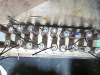
Cylindrical cells like the 18650 aren't exactly known for their energy density. If they are designed correctly, the shouldn't need much airflow through them. In effect, you're shortening their life, then trying to space them out again to regain a small percentage of what was lost.
Yes. I am thinking about just hot gluing the cells all together and throwing out the wood.
Also hot gluing the BMS directly to the pack. Do I need to put a piece of plastic or something between the cells and the back of the BMS ?
It will be small and not take up a lot of room. I put the Lipo charger in storage. I need to get it out. I have 19 cells at about 4.0V and one cell at 3.64V. I will need to charge the low cell before I build the pack.
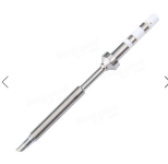
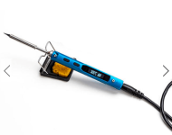
I will switch to a larger tip when soldering the negative terminals. Please let me know how to mount the BMS. Thanks.
8/5/18.
The one pack is already hot glued into the wood. It will be most difficult to remove the cells. The other cells have spots on the side where the wrap is damaged and the metal exposed. I will need to wrap them with electric tape to make sure there is no contact between cells.
Also hot glue together defeats the purpose of soldering wires to the cells. It should be simple to replace a bad cell. If they are all glued together it would be messy and difficult to accomplish. I am developing another method to the madness. Thanks.
8/6/18
I went up the Crane st. hill again with the Currie. I only went part of the way up though. I got a good head start and went about a block and a half or about half way up and when it started slowing down I got off and walked. I only walked about 2-1/2 blocks then went the last block which was not as steep to make it home.
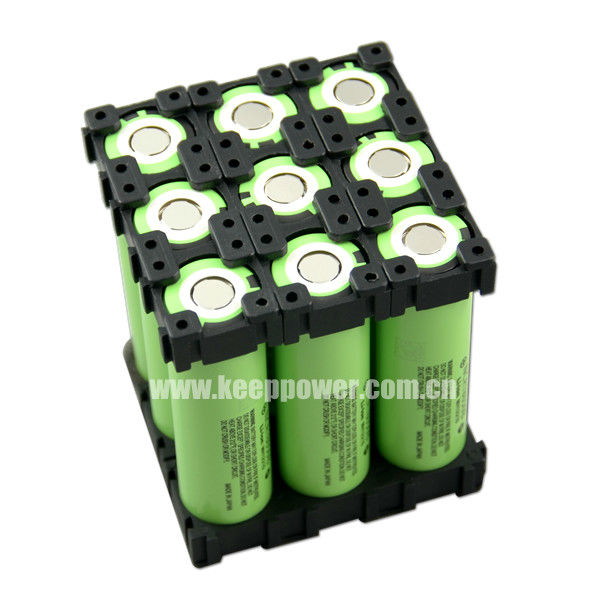
I could have took the entire hill but decided to give my controller and batteries a break. The Motor is probably more than capable of taking that hill as many times as I want it to but don't feel like abusing my equipment any longer. The Currie has proven to be a very reliable e bike with the 750 watt gear reduction motor. Also the 3p - Samsung batteries have proven to work exceptionally well.
The 3p pack voltage reads about 3.96V after a 1.3 mile trip with 1/2 mile being up hills. My trip downtown is about 2.6 miles round trip but I always recharge before returning. I am very happy with three of Samsung packs. I still do not understand why the fourth pack was low in voltage.
The max amount of voltage it will take after being on the charger overnight is 3.97V. I did get a refund for that pack and ran the pack solo to Wall-Mart approx 0,6 miles and 1.5 miles round trip as I went a different way home. Voltage was about 3.75V upon return. I do not think I should combine it with the other three. Also I am wondering if I should order more 36V packs as I don't know if they will send me good ones or not.
My other unanswered question is would it be recommended to combine the Three Samsung packs to the SONA packs. I believe the Samsung packs to be higher in capacity. However they all have a BMS. I could run them all in parallel but charge the SONA packs with a separate charger.
Also I noticed that the 3p pack has much more power than the single low voltage pack. The trip to Wall-Mart and back only require a couple of small hills. Therefore I would like to run the SONA packs with the Samsung packs for 5p. If I charge them separate will that work. Please let me know.
My final question is about the LG cells. I twisted one and it easily came loose so I will be building them a lot smaller. I will wrap some electric tape around each cell then tape the BMS to the side of the pack.It should work out good. Thanks and please let me know.
LC out.