Minimising rotor losses

Regarding the effect of slot and pole count i found this paper:

http://www.jimhendershot.com/Jim_He...ushlessdcmotorphasepoleslotconfigurations.pdf

Chapter "V Stator slots/windings" contains some meaningful informations.

There are graphs where the BEMF voltage and torque curve are shown for different slot/pole combinations.
I found it interesting that for instance the BEMF shape of an 4P12N stator is identical to an 6P18N or 8P24N because they all belong to the same category with three (3) slots per pole.
A stator with 8p18N or 16P18N for instance has a perfect sine-wave BEMF and torque curve with very low cogging torque.
Unfortunately there is no graph of the mentioned 20P24N design (0,833 slots per pole) or the 14P12N (1,166 slots per pole) like the motors from Revolt do have.

The question is if a motor design with sine-wave BEMF and torque curve (lowest cogging torque) would be equatable with an high efficient (low eddy losses etc.) design? Any ideas?

Miles said:
You're on a roll, Lars :)

Thanks for the useful references. Interesting how little the resistance between surfaces needs to be to avoid conduction of eddys.... I guess that's why you can get away with a thin oxide layer on stator laminations.

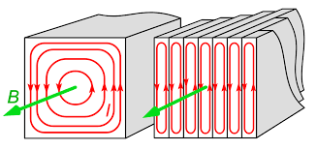
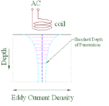
it seems that eddy currents only flow in horizontal direction in very thin "layers" if the alternating magnetic field penetrates the material vertically. Therefore the material is laminated in this direction as the benefit of reducing the eddys is the largest when doing so.
Thats how i understand it. Is it right?

View attachment 3
Download (1).png
images.png

But i still try to find out what happens in the VERTICAL DIRECTION, and thats why the initial discussion started:

- Would there be a benefit to electrically isolating the magnets from the back iron?
- Or would there be any benefit of using epoxy coated magnets instead of magnets with conductive coating like nickel?

I found this paper very interesting:

http://chemical-biological.tpub.com/TM-1-1500-335-23/css/TM-1-1500-335-23_337.htm

4.2.2.1.4 Material Thickness.
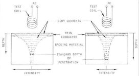
In a part, such as sheet material, in which the thickness is less than the effective depth of penetration, the overallelectromagnetic field is not zero at the back surface. As the back surface gets closer to the front surface, the overallfield at the back surface increases; and as the back surface gets further from the front surface the overall field decreases. This provides a mechanism for thickness gauging of thin materials. Furthermore, a material of either lower or higher conductivity at the far side will change the magnitude and distribution of the eddy currents as shown in Figure 4-6. This provides a means for thickness gauging of thin, conductive coatings on substrates that are either more or less conductive than the coating.

TM-1-1500-335-23_337_2.jpg

Figure 4-6 shows the first material the magnetic field hits is the "thin conductor" which should be the same on both the left and right figure.
On left figure the "backing matrial" has higher conductivity and on the right side the backing material has less conductivity.
It looks like things change a bit in the "thin conductor" on top, but i am not 100% sure about it.

This can be applied between any two different, electrically conductive materials which are stacked in vertical direction. Like magnets on the back iron, or the coating of the magnet (eg. Nickel) on the magnet iteself (NdFeB).
 
Thanks a lot!

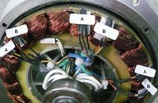
This 6-phase has 30 degrees in space between poles on the stator, 30 degrees in electrical if i read correctly, (i am in the deep here). It's giving the best reduction of harmonics for a 6-phase / 12-slot

I wonder what angle your sensors are in space and electrical degrees? I guess that's an old picture or can you measure?
 
The hall sensors are in the middle of the teeth. I know because the no-load current and rpm at a given voltage are the same whether spinning forward or reverse. The phase angle is 120°. Yes the difference between the 2 sets of timing is a one slot difference or 15° (360°/24 slots).

Something else that may be of interest is that I've run the motor with the halls crossed. I believe the difference is just a 3° difference of advanced timing. I actually rode the bike for a few weeks that way, though I could feel something wasn't right. I hit 103mph with them crossed, but a few weeks later I hit 107mph with the halls going to the correct controller. With them crossed It had significantly higher no load speed (121mph), it made a bit more noise, it had less torque during acceleration, and worst of all the motor ran hotter.
 
@John in CR:
I think 15 degrees in space for your motor is 15*10 (pole pairs) in electrical degrees?
How do you get to 3 degrees difference between the sets of halls?

@madin88:
- Would there be a benefit to electrically isolating the magnets from the back iron?
- Or would there be any benefit of using epoxy coated magnets instead of magnets with conductive coating like nickel?

I'm reading up on the eddy losses and i think there's many things that need to be known.. there might not be any universal truths.

We need to look at frequency that is present and the resulting skin depth in the rotor and magnets. There will be cases when insulation is needed but if the nickel to backiron split is insulation enough..
 
Johnin CR said:
...
The Revolt motors have a pretty common slot/pole count combination don't they? Construction seems pretty normal, so unless all similar outrunners have this rotor loss problem, then it must be a materials quality problem

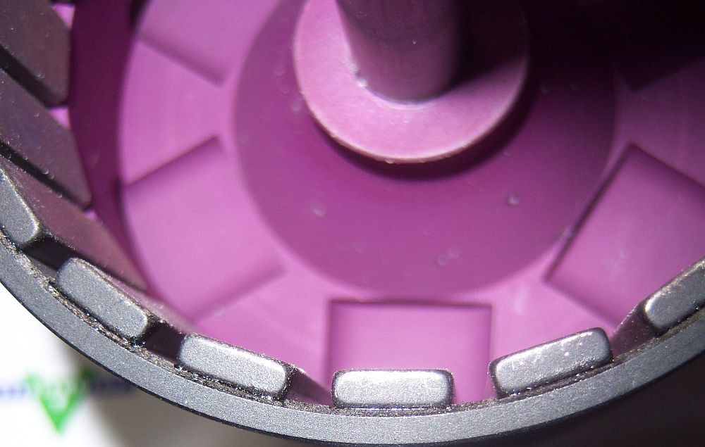
From the pictures the back iron looks way to thin walled. But i have a hard time to understand that this design flaw could be the reason for the high rotor losses? I think it will just lower the (peak) torque as any flux leakage on the back will lower the flux density in the airgap.
The newer E-versions have fins on the rotor which should improve things, and also cooling...
--

As mentioned i plan to do full magnet segmentation on my 8057 motor and today i got a quotation from the chinese manufacturer.
I decided to go with 4 segment's, with a size of 57 x 3,5 x 2,5mm (2,5mm is the thickenss), so 64 magnets in total than for the 16P design!

Normally magnets are Nickel coated (this is standard), but Ni coating than is Ni-Cu-Ni so there even is a layer of copper between.
I was happy to hear they can do the so called "raw epoxy coating" which doesn't contain any other layers of conductive materials.
Those layers are quite thin (around 10-30µm), but i thought if i can choose epoxy and improve things a little bit further with it than why not take it, and the price was not bad :)

I had to pay ca 75USD for 70pcs incl. antimagnetic package and shipping. The grade of the stock mags is N38UH and i decided to go with N42SH.
 
larsb said:
@John in CR:
I think 15 degrees in space for your motor is 15*10 (pole pairs) in electrical degrees?
How do you get to 3 degrees difference between the sets of halls?

Yes a 15° degree difference in hall placement, but magnets are every 18°, so the halls are getting triggered 3° early by another magnet. At least that's how I think it works. Note that you can't just swap the halls connectors, because that's not a valid combo for either, so the new correct wiring config if you get the halls crossed ends up 18-15=3° timing difference. Now it could be that one controller ends up 3° advanced and the other 3° retarded, but I didn't think to check the no load speed with each controller running solo to be sure. The no-load rpm is a bit higher, and starting torque is lower. Also with trap controllers it makes a bit of noise on take-off. Also, I assume there's no way a motor could run that well at 15° timing advance.
 
One way to eliminate eddy losses in the rotor is to run a constant flux
through the rotor in one constant direction. Then, only a solid chunk
of iron without laminations or permanent magnets is required. And no
cogging when idle. Its called a reluctance motor. Some Dyson vacuum
recently had a solid iron rotor that spun 10,000 RPM. Eddies were not
a problem. Creates other problems (like what would the halls sense?),
but those are solvable.

Getting rid the magnets means you don't have to worry bout cooking
them anymore. Neodymium only gives a field strength of about 1.4T,
while plain old iron saturates about 2.2T. More torque is available.

But the stator still has to provide a rotating field to drag that rotor,
so you still need thin laminations and/or powdered and sintered for
those non-moving parts. Cause the field there is definitely changing
direction and intensity. Through both the stator and the windings.

You can upgrade thick winds with thin wires in parallel. Interrupts
eddies in the windings. And when twisted like rope (Litz wire), can
churn current to the interior of the bundle, so you are not battling
the skin effect. Fast alternating currents tend to push themselves
outward to the skin of a fat wire, the interior contributes nothing.
You can have lower AC resistance in spite of a longer twisted path
from end to end, and giving up some copper to insulate all the little
wires that replace it...

Or just wind the motor for as high a Voltage as the insulation will
witstand. More turns of thinner wire, even if its still just one wire,
and not a rope. Or use a thin foil instead of round gives more skin
and less eddies depending orientation. Not good as Litz but cheap.
Its silly to see motors wound with round pure copper wire thicker
than resistive silicon steel lams.
 
I think the topic should remain to be for the losses in rotors in question here:
outrunner surface mounted magnet rotors

It will just get too big of a subject :D we won't be able to separate one design and it's challenges from the other..
 
John in CR said:
Yes a 15° degree difference in hall placement, but magnets are every 18°, so the halls are getting triggered 3° early by another magnet. At least that's how I think it works. Note that you can't just swap the halls connectors, because that's not a valid combo for either, so the new correct wiring config if you get the halls crossed ends up 18-15=3° timing difference.

I see, you're calculating in space degrees, but it is 3*10=30 degrees electric until you hit another magnet which is opposite polarity (that magnet edge is at 180 deg electric from the first position) So diff is 180-30=150 degrees.

How can it still work with the halls crossed?
Could it be the actual hall wiring is different in the connectors so it also changed the triggering of the phases?

@madin88: seems like a good deal on the magnets!
 
John in CR said:
I hit 103mph with them crossed, but a few weeks later I hit 107mph with the halls going to the correct controller. With them crossed It had significantly higher no load speed (121mph), it made a bit more noise, it had less torque during acceleration, and worst of all the motor ran hotter.

So this motor has two sets of phase wires and two sets of hall wires, and each set of hall sensors just works with one specific set of phase wires.
Is that right?

Normally the hall sensor for phase A1 needs to be installed between the two stator teeth where the winding of phase A1 goes into the motor.
Same for phase B and C. If the motor is wound in star, the sensors belong exactly between two teeth, but if the motor is wound in delta, the sensors normally need to be installed in the middle of one hammerhead, like it seems to be the case on your motor (a delta winding requires a hall sensor shift of 30° electrically).

John, could it be that winding A2 goes into the stator at a different place as A1 does? Or with other words: does the start of the windings (where they enter the stator) follow the same sequence as the hall sensors? This would explain everything.
 
Yes 2 sets of phases (on alternating teeth) and 2 set of halls. It may very well be wound delta, but it's impossible for me to tell, since the other side of the stator is covered in a thick high temp black epoxy to stop wire movement due to the greater than usual end winding copper resulting from the every other tooth wind.
 
best way are revese engegnering,the best motor like csiro for low kv or the astromotor for high kv
 
madin88 said:
..
it seems that eddy currents only flow in horizontal direction in very thin "layers" if the alternating magnetic field penetrates the material vertically. Therefore the material is laminated in this direction as the benefit of reducing the eddys is the largest when doing so.

But i still try to find out what happens in the VERTICAL DIRECTION, and thats why the initial discussion started:

- Would there be a benefit to electrically isolating the magnets from the back iron?
- Or would there be any benefit of using epoxy coated magnets instead of magnets with conductive coating like nickel?
..

The motors magnetic circuit has a field loop from teeth through the backiron and back to the teeth. It is meant to go through the backiron and i think this makes motors different to eddy testing.

Field direction is radial direction through the airgap and circumferential through the backiron, this will give different eddy current orientation in teeth vs backiron. See this snip from some motor simulation:
field circuit.JPG

The eddy current plane / normal to field direction in the backiron goes in radial/depth direction 8)
So if magnets and backiron are one unit as far as conduction goes, then the losses will be larger.

But i think along these lines: if the segmentation of magnets is enough to create smaller domains without added insulation even when touching (at least in some cases like the paper we don't have access to :D )
it's just a guess if this is valid also for the magnet to backiron domain..

Either do a trial with two different built rotors or go for full insulation, then you know there's the lowest eddy losses.. :wink:
 
I think you're on to something.

Here's a paper that looks at magnet eddy current losses.
https://ieeexplore.ieee.org/document/6073324/
Not sure if this can be read by anyone, but I could view the full document.

Their test case was a small inrunner motor about like a small bike or scooter motor with the following parameters:

Pole pair number, p 2
Slot number, NS 36
Slot number per slot per phase, q 3
Series turns per phase, N 24
Stator bore radius, DS 49 mm
Rotor outer radius, Dr 47.8 mm
Airgap length, g 1.2 mm
Magnet thickness, hm 10 mm
Sleeve thickness, hsl 0.8 mm
Slot opening, bs 2.8 mm

The Sleeve is a steel band that holds the magnet to the rotor and sits right in the gap.

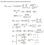
The calculation is the kind of stuff that reminds me why I don't like using simulations:

eddy current calculation.JPG

And after all that, they calculated the loss in the sleeve and in the magnets themselves. In an outrunner motor, there would be no sleeve. The sleeve losses were about 10x more than the magnet losses.


Well, a lot of math but the bottom line is if you keep the motor rpm reasonable, the losses from eddy currents in the magnets is pretty small compared to the other losses.
 
larsb said:
This paper explained a lot to me on the harmonic losses, when they occur and some of the compromises in motor design:
Slot pole Combinations Choice for Concentrated Multiphase Machines.pdf

Very good read. Thanks for posting that!
 
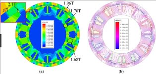
In this thesis both magnet and backiron losses are calculated:
View attachment Eddy Current Losses Calculation in Rotor Back Iron and Magnet.pdf

Interesting is that both backiron and magnet losses are substantial (together it makes 3-5% on the efficiency at 4800 rpm) and that the flux is concentrated on the side towards the magnets.
View attachment 2
Skärmavbild 2018-08-08 kl. 23.13.40.png


If the rotor backiron towards stator would be very coarsely threaded/slotted, let's say with 5mm pitch and a depth of 3mm.. That'd be interesting to try.
Who has access to a large lathe on ES? 8)
And who's doing a motor design currently? Crossbreak or Miles maybe?
 
larsb said:
If the rotor backiron towards stator would be very coarsely threaded/slotted, let's say with 5mm pitch and a depth of 3mm.. That'd be interesting to try.
Who has access to a large lathe on ES? 8)
And who's doing a motor design currently? Crossbreak or Miles maybe?

I would do it with the electrical discharge machining (EDM) which uses a thin wire to erode materials into shape. The slots whould be just as thin as the wire itself, and you would not loose much steel for the flux return (which is think is important too).
Regarding that one paper linked before, a segmentation depth until 30% of the total back iron thickness would be enough.

I found out that LMT does back iron segmentation by using some kind of fine segmentated material between magnets and the solid back iron.
the thickness looks like the 30% or less, as more would not make anything better.

LMT Torqstar 70
FxunZj.jpg


But they don't segment the magnets.
From everything i read it looks like the more poles one motor has, the less the advantage would be of segmenting the magnets as the width of the magnets decrease and so the eddy currents.

Motors with very low pole counts AND stator teeth should benefit the most by doing magnet segmentation.
 
Back
Top