You are using an out of date browser. It may not display this or other websites correctly.
You should upgrade or use an alternative browser.
You should upgrade or use an alternative browser.
bluetooth BMS?
- Thread starter aethyr
- Start date
flippy
1 MW
- Joined
- Aug 12, 2015
- Messages
- 2,351
best thing tou can do is use a suitable meter and measure the resistance of the shunt in place. in my experience they are off by 5% easy.
or just hook up a separate DMM amp meter and tune the number until it matches the known good number on the DMM.
or just hook up a separate DMM amp meter and tune the number until it matches the known good number on the DMM.
eee291
100 kW
flippy said:or just hook up a separate DMM amp meter and tune the number until it matches the known good number on the DMM.
Exactly what I am planning, that's why I asked.
I bought two of the 24S 40A version and will be replacing the Mosfets to hopefully get 150A through it.
ElectricGod
10 MW
izeman said:imho this should be the value for the shunts (got the pics from another guy posted a screenshot on FB)
Capture.JPG
I can measure down to 1mOhm with my 4 wire meter. It's not the best meter there is. Zeroing it is a bit hard with the trim control it has from the factory, but doable. I've checked a variety of shunts that I have and they all measure very close to their rated specs. Finding the actual Resistance of my shunts and busses won't be hard to do. So far, I haven't bothered since I assumed I was close to what was already there.
https://www.ebay.com/itm/VC480-Precision-Milliohm-Meters-vs-Extech-4-wire-kelvin-clip-0-adjust-large-LCD/172139217849?epid=1450142924&hash=item28144c03b9%3Ag%3Aln4AAOSwHnFV5ukB%3Asc%3AUSPSPriority%2180020%21US%21-1&_sacat=0&_nkw=milliohm+meter&_from=R40&rt=nc&_trksid=p2060353.m570.l1313.TR3.TRC1.A0.H0.Xmilliohm+meter.TRS0
Cheap watt meters, these BMS and other inexpensive current measuring deoivices are not going to be very accurate. It's very probable they are a few hundred milliamps off or more. An amp meter is only going to give good results if it's accurate. Since the atmel328 (CPU on the BMS) has 12 bit ADC's, superb accuracy will not happen. Expect to always see some variance from what the BMS reads for current and what anything else reads. If I were to get .1 amps accuracy...that would be good enough. I bet if you measured the actual shunts in the BMS and put that value in the BMS settings that you would NOT get accurate current measuring. It's all about the accuracy of the ADC in the ATM328 and that can be all over the place. On may read .1 volts as actualkly .1 volts and another 328 would measure it as .3 volts.
To calibrate your BMS, you can depend on my values to be relevant to your BMS. I can't even depend on the shunt resistance from one of my BMS to be relevant to another of the exact same BMS with the exact same shunts. It could be close, but who knows what the Atmel 328 ADC reads from one BMS to the next.
To get the best results possible: (Do this for each BMS)
1. Get a milliohm meter.
2. Get a decent DMM.
3. Get a shunt with sufficient amperage for your EV.
4. Measure the actual resistance of the shunt with the mOhm meter.
5. Put the shunt inline with your EV.
6. Using your DMM, measure the voltage across the shunt.
7. V/R=I...now you know the real current with some decent accuracy.
8. You will need the USB adapter and a windows PC.
9. Adjust the value in the BMS up or down until you get close to the real results.
If you have a watt meter on your EV already, I bet the real amperage and what the watt meter reads are off a fair bit. Same for these BMS. It would be shear luck that you got one that was dead on.
ElectricGod
10 MW
eee291 said:flippy said:or just hook up a separate DMM amp meter and tune the number until it matches the known good number on the DMM.
Exactly what I am planning, that's why I asked.
I bought two of the 24S 40A version and will be replacing the Mosfets to hopefully get 150A through it.
Fix the copper busses and use larger shunts too.
Does anybody has an idea about the password of Android app ? It's not 1234, like someone stated few posts ago. Tried every dumb-style passwords (like 1111,2222, 9999, 0000, etc) but no chance.
I have the english version, I'm clicking (in the menu) the option to change the password, but the old one isn't mentioned anywhere.
BTW, it's a number sequence, no letters.
I have the english version, I'm clicking (in the menu) the option to change the password, but the old one isn't mentioned anywhere.
BTW, it's a number sequence, no letters.
Dui ni shuo de dui
10 kW
I see in this thread that some people change the mosfets and shunt resistors on their smart BMS. I kinda wonder why.
I could understand if those things were actually heating, but given my tests this has never been the case.
So unless you are pushing some really, really insane currents through it, I don't really see the point.
Myself, I'm running it at 210Amps continuous and not problem whatsoever, even in hardcore super hot chinese weather it only gets 3-4 degree C above ambiant temperature while riding at full blast for an hour.
A friend of mine pushes more than 500 Amps through the poor 300A rated BMS and we didn't notice any heat building.
So I really wonder if this is actually something useful and not just a silly precaution. I can understand that beefing up the bus bars could be a nice idea given how poorly they are done, but I really see no point in changing the Fets or the shunts. Fets won't heat much if at all if they are not doing high frequency switching (which is the case in a BMS, they mostly act as a big relay to cutoff power), and there are 10 shunts so any current will be divided between those, which, given their individual low resistance, won't generate much heat at all. Those resistor's are designed to actually allow voltage readings while heating as less as possible. They should not heat much, especially since they are 10 of them.
Also, the 10 shunts seems to have been replaced by only 8 shunts on the pictures I saw. Aside from the fact that each shunt will see their individual current levels rising a bit (hence, more heat generated), I wonder if the value has been calculated correctly to take the resistance difference into account (10 shunts to 8 in parallel, not the same total resistance). I guess yes, but I ask the question just in case it hasn't.
As for the accuracy of the power meter readings, they are indeed not super accurate. My smart BMS seem to miss about 5-6% of the total power draw on a full charge. I thought it could be the refresh rate being a bit too low, missing current spikes, but the ADC accuracy also seems like a valid possibility. Just be aware that if you're riding hard you should be careful when the battery meter indicates less than 10% remaining, it can cut off at any moment passed this point since it might not have counted all the power drawn.
izeman
1 GW
Because we canDui said:I kinda wonder why.
But tbh you may be right. It may not be needed but for me personally I feel better with a high quality product and some safety margin. I also can operate the BMS which is rated for 30A in a closed cabinet at 60A constant w/o getting even warm.
izeman
1 GW
not open source - no active community - no communication with the (chinese) developers
there is no special security. if someone has the app and is near your bike he can modify all parameters - but how likely would that be ???
there is no special security. if someone has the app and is near your bike he can modify all parameters - but how likely would that be ???
ElectricGod
10 MW
usertogo said:Sorry for not having read every post in this thread, I wonder how is the communication to the developers (this is not open source, right?) is, can proposals for improvements be forwarded? I really like all the things that are being attempted, and think that the possibility to use GPS data to get to distance and speed traveled should be used to also display current and graph of average mobility efficiency in Wh/km .
This would be so convenient in order to attempt tuning and some day maybe integrate an interface to some GPS solutions, and map of charge points to eventually get to some kind of Open Source Volks Tesla Standard Interface (OS-VTSI?
By the way I have not figured out yet how to set up the smart BMS with some kind of Security that not just anybody with the right APP could simply 'weaponize', make inoperable or destroy my battery?
There is a VERY small community (3 people) working on integrating this BMS into an app. The protocols and commands are known and making that data work elsewhere is actually something that is being worked on. I can't say more than this for now, but assume it is being "worked on" and will see the light of day sometime soon.
As for security, the Chinese app has no place for a PIN. The BT module however could take a PIN. I'm currently looking into connecting with the manufacturer to get changes made such as adding a PIN. We'll see what happens...maybe nothing, maybe a lot.
ElectricGod
10 MW
Dui said:I see in this thread that some people change the mosfets and shunt resistors on their smart BMS. I kinda wonder why.
I could understand if those things were actually heating, but given my tests this has never been the case.
So unless you are pushing some really, really insane currents through it, I don't really see the point.
Myself, I'm running it at 210Amps continuous and not problem whatsoever, even in hardcore super hot chinese weather it only gets 3-4 degree C above ambiant temperature while riding at full blast for an hour.
A friend of mine pushes more than 500 Amps through the poor 300A rated BMS and we didn't notice any heat building.
So far, I have done no modding to these BMS. They seem pretty good as is. I have no complaints about the P- mosfets on them or the copper busses.
https://www.aliexpress.com/store/product/Smart-Display-300A-200A-150A-100A-70A-Lithium-Battery-Protection-Board-Balance-BMS-Coulomb-Meter-Lithium/2856009_32826820690.html?spm=2114.12010612.8148356.3.2cd43de22JQESO
or
https://www.aliexpress.com/store/product/Smart-Display-16-32S-Cells-300A-200A-150A-100A-70A-Lithium-Battery-Protection-Board-Balance-BMS/2856009_32826469363.html?spm=2114.12010612.8148356.1.2cd43de22JQESO
However these BMS have poor mosfets and the copper busses are too short and NOT soldered down on all 7 of them I have. They need fixing IMHO. While I'm in there doing things the factory should have done, might as well make them as strong as possible!
This is upgraded on pages 18 and 24.
https://www.aliexpress.com/store/product/20S-Lipo-LiFePO4-Lithium-Battery-Protection-Board-60V-72V-Li-ion-Cell-Smart-Phone-APP-PC/2856009_32863752220.html?spm=2114.12010612.8148356.41.5fc23de2mMrlYO
or this bigger version on page 25...
https://www.aliexpress.com/store/product/24S-Smart-Lithium-Battery-Protection-Board-BMS-72V-lifepo4-Lipo-86V-Li-ion-APP-Management-Bluetooth/2856009_32872999707.html?spm=2114.12010612.8148356.48.5fc23de2mMrlYO
I've posted previously of what I have found so feel free to reread my posts about the copper not being bonded properly, mosfets not being bonded properly, very low grade mosfets, etc.
If you are getting 210 amps out of a 50 amp BMS that has horrible copper bonding and even worse mosfets AND there are a mere 8 of them rated for 10 amps each, well you are doing something magical. My suspicion is you are confusing the various BMS models presented in this thread. Some don't need modding, others really benefit from it.
vipster76 said:where did you buy the bms fromi wouldnt mind getting my hands on one!
https://www.greenbikekit.com/bms-pcm/smart-programmable-lithium-bms-with-software-modification.html
izeman said:charge balancing is only enabled if the charging FETs are turned on, whereas static is always on...
The manual which came with the JBDTools 1.1 reads:
Balance: turn on balance function.
Chg balance: turn on the balance function during charge. If disabel Chg balance, then static balance, eg: the difference of battery more then 0.4V, then balance work.
Enable is charge balance.
Disable is static balance.
Static balance open condition
1. No charge and discharge current. Just battery and BMS.
( charge current is 0A, discharge current is 0A)
2. Battery voltage more then the balance voltage.
( eg: battery 1 is 3.65V, balance voltage (start voltage) is 3.6V )
3. The difference of battery voltage more then the setting windows value
(eg: windows is 30mV, battery 1 is 3.65V, balance voltage is 3.6V, so 3.65-3.6=50mV more then 30mV, so balance led turn on )
Charge balance open condition
1. In charge stage, have charge current.
( eg: charge current is 0.5A)
2. Battery voltage more then the balance voltage
( eg: battery 1 is 3.65V, balance voltage (start voltage) is 3.6V )
3. The difference voltage of battery and balance voltage more then the setting windows value.
( eg: windows is 30mV, battery 1 is 3.7V, battery 2 is 3.6V, 3.7-3.6=100mV 100mV > 30mV, so balance led turn on)
I'm not ableto make much sens out of this description. It seems neither correct nor complete. Has anyone been ableto figure out the complete balancing algorithm?
r
Dui ni shuo de dui
10 kW
ElectricGod said:If you are getting 210 amps out of a 50 amp BMS that has horrible copper bonding and even worse mosfets AND there are a mere 8 of them rated for 10 amps each, well you are doing something magical.
I'm using the 300A BMS, so no magic here.
ElectricGod said:My suspicion is you are confusing the various BMS models presented in this thread. Some don't need modding, others really benefit from it.
Indeed I did!
I don't know why, I thought it was the same as mine. But looking at the pictures again I see that I was totally wrong. And that you did put 2 other shunts at the back of the PCB for a total of 10, same as the original.
Sorry for this confusion
izeman
1 GW
As simple as i wrote. What else do you need to know?rolf_w said:Has anyone been ableto figure out the complete balancing algorithm?
Bison_69
100 W
Hi guys,
I would need some help please; I purchased lately a smart BMS 16 - 32S / 200A with the LCD display from AliExpress...
https://www.aliexpress.com/item/Sma...363.html?spm=a2g0s.9042311.0.0.745c4c4dKyuqda
In spite of the lack of technical information, I succeeded to install the BMS, the LCD display and link the Bluetooth (which is unstable even using VBMS or Xiaoxiang Android apps) I will probably use the PC version instead with a USB to RS-232 adapter…
https://www.lithiumbatterypcb.com/smart-bms-software-download/
Or the Android to PC soft called “Remix OS’’ (with Bluetooth and etc...)
https://www.fosshub.com/Remix-OS.html
Now I need to know more about the BMS:
1_ if the BMS is connected such as explained on the seller’s website, will it drain the batteries?...
2_ should I use an Anderson power connector (to disconnect after use)?...
3_ will the BMS detect the charger when applied or do I have to use the Android apps to tell the BMS to go in charging mode?… (which would be ridiculous since it is called a smart BMS)
4_ will the BMS keeps its last programming memory when disconnected from the battery pack?...
5_ In the kit there is a small switch to turn on the BMS… but how do you turn it off?... (unexplained)
Special thanks to Inwo and thundercamel which helped me a lot…
The seller was stating that the LCD display was working with 6 to 20Vdc which did not worked for me… the right voltage is 24 to 100Vdc meaning it can be connected to your battery pack.
My battery pack configuration is 21S10P / VCT4 18650
Here are some pictures of my project:
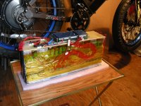
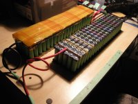
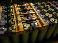
I took the idea from Tesla... I fused all the cells individually in 10P groups with 0.6mm fuse wire found in England (insulator is FR4) https://wires.co.uk/acatalog/cu_tinned.html and use copper to bridge to mount the pack.
Tinned copper fuse wire amp chart... https://electricguru.in/page_view.php?id=29
I also design on CAD (SolidWorks) a LCD display case to mount on the handle bar… it can be 3D printed (PLA or PETG).
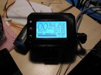
View attachment LCD DISPLAY CASE - BMS.7z
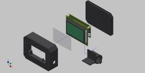
Thank you very much for your help.
I would need some help please; I purchased lately a smart BMS 16 - 32S / 200A with the LCD display from AliExpress...
https://www.aliexpress.com/item/Sma...363.html?spm=a2g0s.9042311.0.0.745c4c4dKyuqda
In spite of the lack of technical information, I succeeded to install the BMS, the LCD display and link the Bluetooth (which is unstable even using VBMS or Xiaoxiang Android apps) I will probably use the PC version instead with a USB to RS-232 adapter…
https://www.lithiumbatterypcb.com/smart-bms-software-download/
Or the Android to PC soft called “Remix OS’’ (with Bluetooth and etc...)
https://www.fosshub.com/Remix-OS.html
Now I need to know more about the BMS:
1_ if the BMS is connected such as explained on the seller’s website, will it drain the batteries?...
2_ should I use an Anderson power connector (to disconnect after use)?...
3_ will the BMS detect the charger when applied or do I have to use the Android apps to tell the BMS to go in charging mode?… (which would be ridiculous since it is called a smart BMS)
4_ will the BMS keeps its last programming memory when disconnected from the battery pack?...
5_ In the kit there is a small switch to turn on the BMS… but how do you turn it off?... (unexplained)
Special thanks to Inwo and thundercamel which helped me a lot…
The seller was stating that the LCD display was working with 6 to 20Vdc which did not worked for me… the right voltage is 24 to 100Vdc meaning it can be connected to your battery pack.
My battery pack configuration is 21S10P / VCT4 18650
Here are some pictures of my project:


I took the idea from Tesla... I fused all the cells individually in 10P groups with 0.6mm fuse wire found in England (insulator is FR4) https://wires.co.uk/acatalog/cu_tinned.html and use copper to bridge to mount the pack.
Tinned copper fuse wire amp chart... https://electricguru.in/page_view.php?id=29

I also design on CAD (SolidWorks) a LCD display case to mount on the handle bar… it can be 3D printed (PLA or PETG).

View attachment LCD DISPLAY CASE - BMS.7z

Thank you very much for your help.
Dui ni shuo de dui
10 kW
Bison_69 said:1_ if the BMS if connected such as explained on the seller’s website, will it drain the batteries?...
Nope.
I've let mine on, with the screen active too, for a whole 2 weeks. I took a picture of cells voltages before and compared with when I came back. The difference was unnoticeable. It would litterally take years to discharge the battery.
Bison_69 said:2_ should I use an Anderson power connector (to disconnect after use)?...
Yeah, put one between your BMS and the controller.
Bison_69 said:3_ will the BMS detect the charger when applied or do I have to use the Android apps to tell the BMS to go in charging mode?… (which would be ridiculous since it is called a smart BMS)
It detects automatically. Otherwise you wouldn't even be able to use the regen.
Bison_69 said:4_ will the BMS keeps its last programming memory when disconnected from the battery pack?...
Yes
Bison_69 said:5_ In the kit there is a small switch to turn on the BMS… but how do you turn it off?... (unexplained)
Press it for 6 secs. You should hear a long beep.
ElectricGod
10 MW
All my BMS modding stuff is found spread across this thread. I figured people might want to know what I did in one concise place so I made another thread for it.
https://endless-sphere.com/forums/viewtopic.php?f=14&t=95853&p=1403576#p1403576
https://endless-sphere.com/forums/viewtopic.php?f=14&t=95853&p=1403576#p1403576
Bison_69
100 W
Hi Dui, ni shuo de dui ,
Thanks you so much for you help!... awesome...


Thanks you so much for you help!... awesome...
eee291
100 kW
So i just received my 40A BMS from Lithiumbatterypcb.com and this is what it looks like on the inside.
https://imgur.com/a/SYshbIc
Looks like the copper issue was fixed a long time ago. it's just that most Aliexpress sellers still sell the older versions.
I am planning on replacing the Mosfets on the B- side and discharge through the P- port, since the C- Mosfets should withstand up to 40A.
https://imgur.com/a/SYshbIc
Looks like the copper issue was fixed a long time ago. it's just that most Aliexpress sellers still sell the older versions.
I am planning on replacing the Mosfets on the B- side and discharge through the P- port, since the C- Mosfets should withstand up to 40A.
ElectricGod said:usertogo said:Sorry for not having read every post in this thread, I wonder how is the communication to the developers (this is not open source, right?) is, can proposals for improvements be forwarded? I really like all the things that are being attempted, and think that the possibility to use GPS data to get to distance and speed traveled should be used to also display current and graph of average mobility efficiency in Wh/km .
This would be so convenient in order to attempt tuning and some day maybe integrate an interface to some GPS solutions, and map of charge points to eventually get to some kind of Open Source Volks Tesla Standard Interface (OS-VTSI?
By the way I have not figured out yet how to set up the smart BMS with some kind of Security that not just anybody with the right APP could simply 'weaponize', make inoperable or destroy my battery?
There is a VERY small community (3 people) working on integrating this BMS into an app. The protocols and commands are known and making that data work elsewhere is actually something that is being worked on. I can't say more than this for now, but assume it is being "worked on" and will see the light of day sometime soon.
As for security, the Chinese app has no place for a PIN. The BT module however could take a PIN. I'm currently looking into connecting with the manufacturer to get changes made such as adding a PIN. We'll see what happens...maybe nothing, maybe a lot.
So, can we use another bluetooth module (like HC-05) which is more widely supported, which can be programmed with a password ?
ElectricGod
10 MW
rio9210 said:ElectricGod said:As for security, the Chinese app has no place for a PIN. The BT module however could take a PIN. I'm currently looking into connecting with the manufacturer to get changes made such as adding a PIN. We'll see what happens...maybe nothing, maybe a lot.
So, can we use another bluetooth module (like HC-05) which is more widely supported, which can be programmed with a password ?
The BT module currently used supports a PIN already. That's NOT the problem. The problem is the app on your phone...it doesn't support a PIN.
ElectricGod
10 MW
eee291 said:So i just received my 40A BMS from Lithiumbatterypcb.com and this is what it looks like on the inside.
https://imgur.com/a/SYshbIc
Looks like the copper issue was fixed a long time ago. it's just that most Aliexpress sellers still sell the older versions.
I am planning on replacing the Mosfets on the B- side and discharge through the P- port, since the C- Mosfets should withstand up to 40A.
eee291...thank you for the link to your images! They gave me further ammunition for what I've been saying all along.
NOTE: When you read this, understand a few details. These BMS do a pretty good job of balancing your pack and they are a cheap, effective smart BMS. However they lack sorely in some key areas...which I focus on below. And have focused on previously. Fixing the below items makes these BMS pretty darn good!
I do like the 40A version becasue it has less garbage mosfets to remove and replace! Assuming the Chinese HY3215 is anything like the IRL3215, those specs are below. Commonly Chinese parts are NOT as good as the legit part they copy. If you look closely, one of the mosfets is an HY3712 (4th from the left in the below picture). Doh!
IRL3215 or HY3215 specs:
166 mOhms Rds, 12 amp, 80 watt, 150v (Can you say horrible mosfet?)
2SK3712 or HY3712 specs:
580 mOhms Rds, 9 amp, 40 watt, 250v (That won't be a problem at all mixed in with the 3215's! Can you say horrendous mosfet?)
Replace with AOT2500 mosfets. They are your best bet in 150 volt parts.
There's a total of ten 4 mOhm .5 watt shunts on this BMS. That's .4 mOhms total. I wonder what the PC app says the resistance is? In the 50 amp version which has 10 of these shunts, it says .2 mOhms.

I would have to emphatically disagree about the copper issues are "fixed". It looks like the copper is at least flat so maybe it's soldered down completely now. There is solder flow around the edges of the copper so that's good....on the top of the board at least.

Partial copper at P-. That's 1 of the 2 most important places for copper to be placed! No where does any existing copper cover the entire buss or extend onto the solder pad where you connect. At the B- terminals the copper needs to actually touch the screw terminals and have good solder connection to them. Look at the mosfet legs that goe to the copper. There is no solder at all that connects the leg to the copper. This is 100% depending on the thin circuit trace for all current. Same for around the shunts.

I know this is the 40A version, but the copper ought to cover the entire buss and no copper at all at P- is just bad.

No copper overlapping the P- solder pad...or even close to the solder pad. Solder is an average conductor...and that's for legit, good quality 60/40 solder NOT the low grade garbage Chinese solder these BMS have on them. Using solder to make a large current path is not advisable...that's why copper is used...it is a great conductor. Solder should bridge the gaps between the circuit trace and copper or part and circuit trace. It should NOT be the actual current path.

This is a close-up of the underside of the board and the angle isn't great. The copper has no solder flow around it and it looks lifted off to me on the right end. None of the copper on the bottom of the board shows any evidence of solder flow around it. I bet it's all barely attached.

eee291
100 kW
I agree with you on the copper length, but it is soldered down completely which is why it's gonna be a pain in the butt to remove it.
ctirad
10 W
Does anyone know what joints to add/remove for the 22s configuration?
Similar threads
- Replies
- 2
- Views
- 165
- Replies
- 5
- Views
- 823


