kWeld - "Next level" DIY battery spot welder

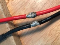
PaulD (and anyone else reading this thread), please shorten the cables as short as possible to reduce inductance. Keep the cables between the battery and welding device a sort as possible, and also between the welding device and the electrode tips. Short and fat is best.

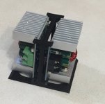
I am also designing an elevated platform to allow the battery-pack to slide underneath the welding device. I would advise anyone with one of the recent "pocket spot welders" (6-pence, Boss level, arduino) to build something similar.
 
garolittle said:
:shock: Now that’s what I call an incredibly good set up!
Thanks! This is the second revision, the third will have some needle bearings in between the two plastic electrode holders to reduce friction, and keep the electrodes well aligned.

spinningmagnets said:
PaulD (and anyone else reading this thread), please shorten the leads as short as possible to reduce inductance. the cables between the battery and welding device, and between the welding device and the electrode tips. Short and fat is best.

Good call, Ron. I had 4 ga with my old welder (vs 8 ga). I'm working on a mount for my battery that will allow shorter cables.
 
garolittle said:
Will do and thanks. I noticed that the amps stayed near 1,000 most of the time. Is that normal?
That is on the low side for the Turnigy graphene that you have. They deliver 1300-1400A here. What battery connector do you use, are all bots tight? Please also check that the electrode holder set screws are tight.

garolittle said:
I also had 2.77 milliohms of resistance at calibration which seemed within the normal range. Awesome product.
The numbers that I get here with the new electrode system are a bit lower than that, less than 2.5mOhm. Please keep in mind that the kWeld is not a precision current measurement instrument, the target here was to be repeatable and not necessarily to be accurate.

PaulD said:
Got mine hooked up, and it's producing good welds. It's replacing an arduino timed DIY welder. Only using 30J for 0.2mm nickel. I'll be experimenting with higher energies soon. I just need an on/off switch since the battery terminals are bolt-on. I'll try a big high current boat switch and see if that holds up and doesn't add too much resistance.
That looks awesome! Can I use it for my web site?

Your battery looks quite small, how many amps does it do?
 
PaulD said:
tatus1969 said:
That looks awesome! Can I use it for my web site?

Your battery looks quite small, how many amps does it do?

Thanks, and no problem, you can use the picture.
The pack is 10.5ah, 15A peak. It's for a lightweight, lower power drive.
Thanks@pictures. Regarding current, I meant what current level do you get with kWeld?
 
tatus1969 said:
Thanks@pictures. Regarding current, I meant what current level do you get with kWeld?

Ha, oops, yeah that makes more sense. I get about 880-900A. BTW, I bumped up my energy to 40J, and I'm getting stronger welds. Ron, I attached a pic of the tabs and the fixtures I use to bend them to mate up to the BMS. Hope this helps.

 
Here's a quick sketch of the stand I'm working on. For rapid prototyping I like to use wood. Cheap and non-conductive. The main idea is to make the welding cables as short as possible before I begin experimenting with the highest settings to see how much it can take, concerning nickel-plated copper and possibly brass.

The first idea is to make some type of elevated stand, so the 18650 battery packs can be moved around into any orientation in relation to the electrodes. Since the height of the stand can easily be made to be adjustable, the stroke on the electrodes only needs to be one-inch or less.

The kWeld would be located on top of the flat section.

Doing this allows the cables to be extremely short, easily 1/3rd the current length. This means that inductance would be significantly reduced. The cables from the other end of the kWeld could also be very short whether using a LiPo pack, a car battery, or the kCap super-capacitor bank.


View attachment 1

SpotWeldStand2.png

Although being able to fold-back the two front stand supports is not a requirement, it is easily accomplished, so storage would be easier. Suspension coil-springs for the electrode arms are not shown, as are a variety of other features. I'm not saying this is a great style of stand for me, or even a good stand for anyone. It's just an option.


Although this new stand design would change the orientation of the hole that clamps onto the electrodes, this earlier version pic shows some of what I intend. The board shown is a 2 X 3.

file.php
 
really spinner move to China and set up next to Paul he's a good guy. Ok what I have a problem is what kind of busbar are we going to use to transfer the current of say something like a Samsung 25r cell to a bike size battery. Like 20s 8p ?1
 
999zip999 said:
Ok what I have a problem is what kind of busbar are we going to use to transfer the current of say something like a Samsung 25r cell to a bike size battery. Like 20s 8p ?1

How about a larger version of this? You could use the same pattern but make it 20S 8P.
 
tatus1969 said:
Your needed energy levels appear too high for me, can you please check and repeat calibration a few times, pressing the tips hard together, and see if you get repeatable results (keep the foot pedal down after "short")?

I tried the calibration again and got the same results for resistance: 2.77. Resistance has a range of 1.0 to 2.0 when welding and my amps range between 890 and 1,110 amps. Part of the problem may be the connector I am using. I am using an XT90 to connect the lipo pack to the Kweld input cables. To connect the lipo female XT90 with a male XT90, I had to solder 8 awg to 10 awg wires and this may be part of the problem. See picture below of the soldered wires before I added the heat shrink. Could this be the cause of the lower amps?
 

Attachments

  • 4D10F86A-E174-4ECA-A449-00B77C933831.jpeg
    4D10F86A-E174-4ECA-A449-00B77C933831.jpeg
    67.9 KB · Views: 2,704
Over my paygrade Mr methods has I better grasp on what's going on with maths knows much much on thr tip of hiis brain. But yes I was thinking of a copper bus bar supporting the load between the parallel cells as the series needs to hold the load and the parallel groups share the load like lovers of the 60s.
 
garolittle said:
Part of the problem may be the connector I am using.
It is only a problem if you get unsatisfactory results. If not, then it's just an observation (and me scratching my head) :wink:

garolittle said:
I am using an XT90 to connect the lipo pack to the Kweld input cables. To connect the lipo female XT90 with a male XT90, I had to solder 8 awg to 10 awg wires and this may be part of the problem. See picture below of the soldered wires before I added the heat shrink. Could this be the cause of the lower amps?
That could be part of it, although your joints look good. That piece of 10AWG also adds to it. You should be able to solder an XT90 plug onto 8AWG, I am doing that here and it fits (just).
 
I am so impressed with this spot welder. Here are a few pictures of an experiment I conducted today. I used two .15mm pure nickle strips and spot welded using 25J or 30J. Very consistent welds. I could barely pull the strips apart the welds were so strong. :D

IMG_1671.jpg
 
By the way, my friend Ron (spinningmagnets) is correct. You get much better spot welds when you use strips with a small slit in between the contact area of the electrodes. You can literally watch a streak of energy "shoot across" to the other side of the nickel strip when you use this method. See black arrow in picture below. Really cool and really strong weld.
 
999zip999 said:
Have you tested the fuse wire to see how many amps it can survive ? Getting that welder dialed in like a pro.

The Kweld provides perfect spot welds on pure nickel strips but I have not mastered the art of spot welding the fuse wire directly to the cell. I ran a few experiments with 24 awg and 20 awg and got mixed results. I am convinced the problem is me and not the Kweld unit. I am going to try a few things like flattening the electrode tips and even carving a very small “groove” on the tips to see if that results in consistent welds. I actually fuse two wires at a time in order to “force” the weld current to run through each wire. I would then choose the one with the best weld if I were using this method on an actual battery pack. The pictures below show the results. The red battery has 20 awg fuse wire and the green battery has 24 awg. I cheated a little by flattening the end of the fuse wire with a hammer. :)

CF2B3118-59BF-4275-99E4-B69D54195171.jpegDBDE14E9-4F15-4617-A312-35EE8C7A6EE5.jpeg
 
garolittle said:
I have not mastered the art of spot welding the fuse wire directly to the cell
Can you maybe describe what happens? Do you get unstable results, or won't the wires stick at all?

Copper is much harder to weld, because it has multiple times the electrical and thermal conductivity over nickel.

20AWG is thick - that should easily survive more than 30A. What trip current are you targeting?
 
tatus1969 said:
garolittle said:
I have not mastered the art of spot welding the fuse wire directly to the cell
Can you maybe describe what happens? Do you get unstable results, or won't the wires stick at all?

Copper is much harder to weld, because it has multiple times the electrical and thermal conductivity over nickel.

20AWG is thick - that should easily survive more than 30A. What trip current are you targeting?

Thanks Sir. Here is the story. The tinned copper wires (20 awg) do stick some of the time but I have not figured out how to do it consistently. I think the problem may be that the wires are round and the electrode tips are "rounded". Therefore, the contact area between the two surfaces is not large and sometimes electrodes may "slip" off a little resulting in an inconsistent weld. I will build a 20P14S pack of 18650 cells using brand new Samsung INR cells rated for 20 amps continuous current. My electric go kart will have a Motenergy motor and Alltrax controller capable of 150 ams continuous and 300 amps max (for one minute). I am experimenting with the 20 awg to guard against any possible "internal short" that may occur. With a "20P" pack, I believe I could use 24 awg but I wanted to reduce resistance and voltage drop as much as possible so that is why I tried the 20 awg tinned copper wire. However, the results were better with 24 awg so I may give that a try again. Basically, I am trying to build a much larger version of the prototype pack shown below. If I can just master the art of spot welding the fuse directly to the cells I will have exactly what I need. Any suggestions are very much appreciated. Either way, I really like the Kweld unit and I highly recommend this spot welder for anyone considering such a purchase. IMG_1121.JPG
 
garolittle said:
The tinned copper wires (20 awg) do stick some of the time but I have not figured out how to do it consistently.
I think part of the problem may be that your welding current is on the low side, you wrote that it is around 1000A. If current is too low, then the required pulse time becomes too long, which allows the heat to spread away from the weld spot. Can you add more cells in parallel to your kWeld supply battery, in order to crank up the current? I would guess that you would need at least 1400-1500A to obtain good results for AWG20 fuse wires.
 
You are probably correct. I will I had another battery in parallel. Recently I noticed that the “weld time” would gradually increase as I continued spot welding. I am getting excellent welds with .15 mm nickel strips but the results were a little inconsistent with the tinned copper wire. The amps for each weld ranged from 890 - 950 for 25-30J so I suspect it is a resistance issue.
 
tatus1969 said:
Can you add more cells in parallel to your kWeld supply battery, in order to crank up the current? I would guess that you would need at least 1400-1500A to obtain good results for AWG20 fuse wires.

Just to be clear, I need to put two of these in parallel? Correct? Thanks for a great product Sir!
 

Attachments

  • IMG_1730.jpg
    IMG_1730.jpg
    60.8 KB · Views: 2,510
garolittle said:
Just to be clear, I need to put two of these in parallel? Correct? Thanks for a great product Sir!
Ah, I didn't recall that it was you who had got a weak Turnigy graphene pack. A second battery would certainly help, or you could add a decent 12V ultracapacitor. It is a pity that my kCap design doesn't go up to 12V, otherwise that would have been a perfect fit.
 
tatus1969 said:
Ah, I didn't recall that it was you who had got a weak Turnigy graphene pack. A second battery would certainly help, or you could add a decent 12V ultracapacitor. It is a pity that my kCap design doesn't go up to 12V, otherwise that would have been a perfect fit.

No worries. I may give another Turnigy graphene pack a try. Thanks for an awesome product.
 
If anyone is interested I made a little mount for the step down buck converters a few people are using. I can/will share the files to thingiverse as soon as i also have a base to join two of these together (I'm will using 4 of them)
 

Attachments

  • 2018-09-15_18-42-49.jpg
    2018-09-15_18-42-49.jpg
    44 KB · Views: 2,357
NIce work! a definite improvement - I like the automated feature - wish
I could get it implemented in my dual pulse unit.... anyway....
Couple quick questions:

1. Which PIC/MCU is used? ((not that it matters - just curious))

2. Will cleaning the electrode tips help with the "resistance issue"? I use
a dual pulse welder built from an E.S. thread a few years ago and find keeping
my tips clean of carbon build up really helps with weld-spot quality. I
use tungsten electrodes - here it's called elkonite.

3. Since the kWeld unit (if I understand correctly) measures the weld-point
resistance for each weld, is it possible for it to also calculate the
required energy to make that weld vs manually setting a number of joules?
Of course, an additional needed parameter would be the type of tab
material/thickness; but it would seem trying to keep a uniform
pressure by hand (and thus bonding contact) on the electrodes
may be compensated by calculating the required energy needed
for a given contact resistance..... or am I trying too hard???
Thanks.
 
Back
Top