KT motor controllers -- Flexible OpenSource firmware for BMSBattery S/Kunteng KT motor controllers (0.25kW up to 5kW)

Why those converters blew up is still unclear. Maybe it doesn't even have anything to do with switching off PWM but rather with voltage spikes "backfiring" when testing without load.

I still wouldn't call it "stable" though until there isn't a good explanation what's actually happening.
 
stancecoke said:
Nice work! Xnyle and me, we both have replaced the resistor and the LM317 by a DC/DC converter and both have trouble with them... I burned 4! :shock: converters while experimenting with switching off the PWM while no power is wanted and switching it on again when power is needed while the bike is moving... I buyed a pack of ten, so I was able to fix the controller fast :)

I did try a 12/5v buck converter a while back, but lost confidence in it after a couple of random mosfet failures and reverted to the stock setup. I think in our application these supplies need to be super reliable, so maybe sticking with the LM317 is the best (least bad..?) option... :?
 
geofft said:
so maybe sticking with the LM317 is the best (least bad..?) option... :?

Hm, perhaps you are right, but I never had problems with the buck converter until I started experimenting with disabling/enabling the PWM. And it seems logical that there are current/voltage peaks when the PWM does not start syncron to BEMF...

So I have to take a longer testride to prove the concept of the new branch...

regards
stancecoke
 
stancecoke said:
Today, I broke the shaft of my BMS-Battery bottom bracket torquesensor, too. Sadly I can't find casainho's pictures with his broken part, to compare if they broke in the same area...
I can confirm that looking at your pictures, mine broke on the same place!! :-( :-(
 
I took a testride with the torque-override branch now. It works as expected, you get assistance from standstill and the pure torque signal overrides the torquesensor-mode (factor*torque*cadence) if it's higher.
meaning of the loop state:
5: PAS timeout
6: torquesensor-mode
10: torque override

regards
stancecoke


index.php
 
Latest firmware compiling with errors, if "speed sensor = external" marked in configurator:

ACAsetPoint.c:73: syntax error: token -> 'if' ; column 3
ACAsetPoint.c:75: warning 85: in function aca_setpoint unreferenced function argument : 'ui16_time_ticks_between_speed_interrupt'
ACAsetPoint.c:75: warning 85: in function aca_setpoint unreferenced function argument : 'ui16_time_ticks_between_pas_interrupt'
ACAsetPoint.c:75: warning 85: in function aca_setpoint unreferenced function argument : 'setpoint_old'
sdcpp.exe: fatal error: when writing output to : Broken pipe


BTW, about "external" (internal on geared motors with white wire in motor cable) sensor - some Bafang drive (i have SWX02 and BPM) has 6 magnets, and generate six pulses per wheel revolution. Original firmware show speed correct with "P2=6" KT-LCD3 setting, this firmware show incorrect "speed*6" :(
 
First, thank you all for your work on the firmware and documentation surrounding the KT controllers and their analogues.

I've flashed it - but have been unable to test .... because I hadn't taken any good (helpful) photos of the internal wiring/pads before rewiring it. Heh.

It's the 18 Fet controller, KTE-18S5-2RX, which I think (?) has the same pad assignments as the 12/15 Fet models.

At any rate, I'm primarily interested in the Brake + Throttle pads. Although, a list of the stock connections would be phenomenal for myself and the community. I'm 98% sure that this information is nowhere else online.
 
kkm said:
Latest firmware compiling with errors, if "speed sensor = external" marked in configurator:

there was just a semicolon missing in line 69 ;). I've fixed it at github. But the refactored code is not proven yet. Perhaps you can test it and give us feedback.

kkm said:
BTW, about "external" (internal on geared motors with white wire in motor cable) sensor - some Bafang drive (i have SWX02 and BPM) has 6 magnets, and generate six pulses per wheel revolution. Original firmware show speed correct with "P2=6" KT-LCD3 setting, this firmware show incorrect "speed*6" :(
feel free to add the parameter PULSES_PER_WHEEL_REVOLUTION to the code :D
Until we have not implemented this feature you can use a workaround by setting the wheel circumference to one sixth of its real value.

randysway said:
It's the 18 Fet controller, KTE-18S5-2RX, which I think (?) has the same pad assignments as the 12/15 Fet models.

At any rate, I'm primarily interested in the Brake + Throttle pads. Although, a list of the stock connections would be phenomenal for myself and the community.
Welcome to the project! Can you post a photo of your controller and a source where to buy it?

BTW, I've optimized the torque override function in the related branch. The override is now ramped down with speed, so you get assistance from the direct torque signal mainly at acceleration from standstill. That avoids a pulsating assistance when you are already in motion.

index.php


regards
stancecoke
 
These are the photos I took when I first got the controller. It's external branding is "RisunMotors", and appears to be identical to one posted (by you stancecoke?) on the bitbucket site.

Branding changes AGAIN on the amazon listing - a company called "HalloMotor"
https://www.amazon.com/gp/product/B01MG78LSL/ref=oh_aui_search_detailpage?ie=UTF8&psc=1

glcv9C2.jpg

y77wcgR.jpg

eadilLm.jpg

YDKm2fI.jpg

umPqnmz.jpg
 
randysway said:
These are the photos I took when I first got the controller. It's external branding is "RisunMotors", and appears to be identical to one posted (by you stancecoke?) on the bitbucket site.

Branding changes AGAIN on the amazon listing - a company called "HalloMotor"

luckily these 18fets are all the same, I got 3, each from different seller. Are you running the custom FW?

BTW I recommend to add the missing big capacitor near battery cables. I have added even more, It helps not to blow your fets by voltage spikes at high phase amp. I was able to run 100A from battery shortly.

and an interesting find from yesterday, for those who want to change fets, there are smd resistors for each fet, 6fet has 101 value 12fet has 510, 18fet has 310. you have to change them to suit your gate charge.
I have changed 6fet to csd19536kcs fets and put 390 resitors (went from 9.8mOhm to 2.3mOhm fets) If Iam correct, It should work and run 40A real easily. gonna test soon
 
honya96 said:
BTW I recommend to add the missing big capacitor near battery cables. I have added even more, It helps not to blow your fets by voltage spikes at high phase amp. I was able to run 100A from battery shortly.

and an interesting find from yesterday, for those who want to change fets, there are smd resistors for each fet, 6fet has 101 value 12fet has 510, 18fet has 310. you have to change them to suit your gate charge.
I have changed 6fet to csd19536kcs fets and put 390 resitors (went from 9.8mOhm to 2.3mOhm fets) If Iam correct, It should work and run 40A real easily. gonna test soon
You guys should be writing wiki pages, structuring this kind of information!!

I bet this motor controllers will be on the market for next years!!

I hope to start soon a new project: develop firmware for the new color LCDs, the ones the starts at 60 euros but gives a great flexibility!! Big display should let us implement kind of that graphs in real time that Stancecoke is showing of current, or motor temperature, etc.

I think I am going or with Kunteng new color LCD or the Bafang color LCD. Both of this are popular, easy to buy and kind of cheap. Banfang, we already know are easy to develop for and has huge memory size of 512kbytes of flash memory!! (KT motor controllers and LCD3 has only 32kbytes if flash memory).
Also we know that Bafang will add Bluetooth to this LCDs on next versions.

All this LCDs communicate using UART just like KT, TSDZ2, Bafang, etc, so this LCDs will be compatible with an big range of motor controllers. So please invest in a good wiki documentation for KT motor controllers because they will for sure be in the market for next years.

On TSDZ2 firmware, we are alreay a few developer/users editing the wiki pages -- sharing the efforts between us make the project going further!!

[youtube]kSpgTWJCjIA[/youtube]
 
The question about "max current" values in the latest (C#ROME-B ) firmware versions.

What method of calculation and document is true now?

"new" configh.h (~sep. 2018 in Master branch)

#define BATTERY_CURRENT_MAX_VALUE 150L
#define PHASE_CURRENT_MAX_VALUE 300L

https://opensourceebikefirmware.bitbucket.io/windows_instructions/index4.html

"Battery Current max: maximum battery current in deziAmps. A value of 150 means 15A.
Phase Current max: maximum phase current. Calculation like Battery Current max. The phase current is derived from the formula phase current = battery current / duty cycle internally."


"old" config/h (~aug. 2018)

#define BATTERY_CURRENT_MAX_VALUE 662L
#define PHASE_CURRENT_MAX_VALUE 532L

https://github.com/stancecoke/BMSBattery_S_controllers_firmware

Reamde.md:

"Battery Current max: maximum battery current. Calculation: Value = desired current in ampere multiplied by the value from field Battery Current cal a minus value from field Battery Current cal b. Example with the default values for limiting to 15A: 15A *10 - (-312) = 462

Phase Current max: maximum phase current. Calculation like Battery Current max. The phase current is derived from the formula phase current = battery current / duty cycle internally."


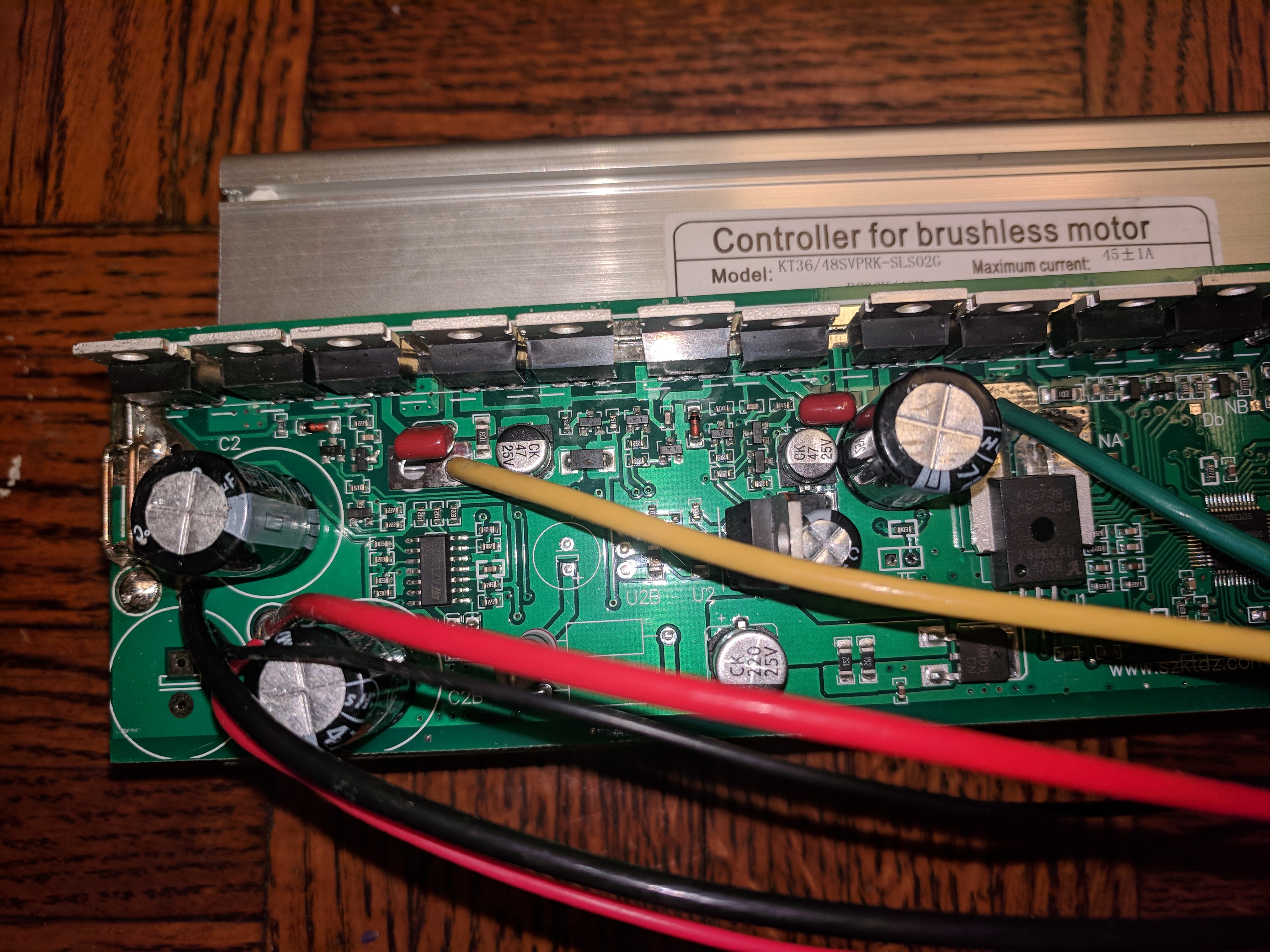
In my case, the values 170/300 (in OSEC GUI ) give a full load power of 1250-1300W on a KT-LCD3 (36V battery). In the case of stock firmware, power was not more than 600-650W. I have 17A KT-SVPR controller from "pswpower".

Flexible OpenSource firmware works excellently on all my geared motors - Bafang SWX02, MXUS XF15R and XF08. Very quiet, there are no unpleasant vibrations and some resonances on the ebike frame (as it was on the stock firmware).
But ... Thumb throttle control... Very accurate and predictable work on the original firmware (and other Chinese controllers), the acceleration is predictable, the response of the thumb throttle is accurate, and it is easy to maintain the selected speed.

Now... I practically cannot use the throttle knob - poorly predicted work, it is difficult to control the chosen speed, "viscous" acceleration.
I only use the throttle knob, and do not use PAS.

This this due to the different types of throttle control? "Speed control mode" in stock, and "electric current" control in flexible firmware?

Small "Safety" issues:
1. Power on controller with thumb throttle at non-zero position - motor start. Dangerous... All other controllers blocked motor in this case
2. Motor start, if voltage on thumb throttle hall sensor > 4.2V (short circuit in throttle cable (betveen +5 and hall signal), or broken hall, and.... :evil: ) All other controllers blocked motor startup in this case...
 
casainho said:
the ones the starts at 60 euros but gives a great flexibility!! Big display should let us implement kind of that graphs in real time that Stancecoke is showing of current, or motor temperature, etc.

Great! Here it is for 52$
https://s.click.aliexpress.com/e/c8L1svHA

There is also a vertical version if you scroll down.

If you plan to change the layout completly it will be great to have batterry % not bars.

Will it help you if the microprocessor wasnt read protected? You can try contacting kunteng's sales man directly at szktdz.com maybe they will understand that they will sell more if you moddify it. :roll:

But I guess you want to start from scratch
 
"viscous" acceleration.

Might be because definition of max current changed: It's now value/cal_a (without cal_b) so if cal_a is 10, 20 Amps would be 200, if cal_a is 5 as on 12 and probably 18 FET controllers, 20 Amps would be 100.

Regarding your "requests", why don't you create a pull request if you have an improvement in mind?
 
honya96 said:
Great! Here it is for 52$
https://s.click.aliexpress.com/e/c8L1svHA

There is also a vertical version if you scroll down.
I am waiting to receive the horizontal version of KT and the vertical version of Bafang (Bafang also has horizontal version). For what I could understand, seems the vertical are more popular on Bafang users.

I am afraid that KT color LCD has low flash memory... because TSDZ2 color LCD uses STM8 and has only 32kbytes, the user that is developing firmware to it says it has troubles because of the very limited amount of memory. I hope KT LCDs aren't cheap because of low memory.... on the other side, the Bagang LCD with 512kbytes of flash memory is much more than what I expected.

I hope soon to have both LCDs in hand and discover about this questions.
 
Xnyle said:
"viscous" acceleration.

Might be because definition of max current changed: It's now value/cal_a (without cal_b) so if cal_a is 10, 20 Amps would be 200, if cal_a is 5 as on 12 and probably 18 FET controllers, 20 Amps would be 100.

Regarding your "requests", why don't you create a pull request if you have an improvement in mind?

Don't really understand what he means but sounds a bit like a slow PI controll..? I had problems with this too. Slow reaction to adding and releasing throttle (few months back)
 
honya96 said:
luckily these 18fets are all the same, I got 3, each from different seller. Are you running the custom FW?

Ha, yes and no. I built + flashed it without issue... but I haven't been able to run it yet. I figured I'd rewire all the external leads while I was adding the STLink + UART(bluetooth) jumpers. However, I forgot to keep track of the connections as I removed them from the board.

Reassembly was a bit of a guessing game... haven't gotten the controller working since. I'm assuming this is due to miss wiring either the LCD leads or Motor Hall leads.

honya96 said:
BTW I recommend to add the missing big capacitor near battery cables. I have added even more, It helps not to blow your fets by voltage spikes at high phase amp. I was able to run 100A from battery shortly.

Good Call. I've been a little disappointed in the 38A upper limit I've been able to pull with it. Especially compared to the Variable Voltage 18 Fet Sunwin controller (2800W off a 13s9p!!).

BTW, If you have the pad assignments for Throttle, Hall V+ and Brake Low, written down somewhere, mind sharing them? I'm getting better at tracing leads back to the CPU pins, but I don't think practice is going remedy the headache. :D
 
randysway said:
BTW, If you have the pad assignments for Throttle, Hall V+ and Brake Low, written down somewhere, mind sharing them? I'm getting better at tracing leads back to the CPU pins, but I don't think practice is going remedy the headache. :D

Throttle plus - TH
Signal - TS
Gnd - G2

First picture is red,white hall and yellow pas signal

Second picture is hall signal

Third is display

4th is brake.
 

Attachments

  • 20181001_002950-1134x2016.jpg
    20181001_002950-1134x2016.jpg
    168.4 KB · Views: 2,326
  • 20181001_003031-1134x2016.jpg
    20181001_003031-1134x2016.jpg
    176.1 KB · Views: 2,326
  • 20181001_002835-1134x2016.jpg
    20181001_002835-1134x2016.jpg
    154.1 KB · Views: 2,326
Hello friends!
I do not understand much about compilers.
I find this project very interesting and useful. I am trying to find the Hex File and the best circuit for this project without seeing. I need some help.
I'm so grateful.
Thank you very much!
My email:
huongtandong2009781@gmail.com
 
honya96 said:
Valopallo said:
Ok. Finally got the time to open the battery case. Do these pictures give any information about my BMS or it's overcurrent protection?

https://imgur.com/a/30EvYLc

EDIT: Found it. http://www.spardbattery.com/PW-10SM-30092-2-20

If you need more power, you can connect discharge without bms, just a fuse. And still have safe charging through bms. :wink:

Ok. Interesting. If I bypass the BMS when discharging, how much current can I get out from my cells? The cells are marked as Samsung ICR18650-26F with rating of 5A continuous work current. Is there some way to calculate the discharge current limits for the whole pack then? The BMS specs say peak work current is 60-100A. So how does this relate to the scenario if anything at all? Also, one more question; If I discharge without the bms, I simply just mod the battery pack's discharge line so that the current bypasses the bms and instead passes only through the fuse, right?
 
Right, easy.

But I wouldnt push them too much over these 5A..

Install a $1 thermometer on it, temp and voltage drop under load is the only limit.

you can't run 40A.. But more than 15 for sure.
 
honya96 said:
Right, easy.

But I wouldnt push them too much over these 5A..

Install a $1 thermometer on it, temp and voltage drop under load is the only limit.

you can't run 40A.. But more than 15 for sure.

Ok. Just for the clarification; is the S12S's 25A max current too much for these cells?

I calculated the capacity of the battery pack as follows;

Max. Discharge Current: 5200mA
Nominal Capacity: 2600mAh
Battery pack capacity: 10.4Ah

5,2A/2,6Ah=2C
2C*10,4Ah=20,8A

So the maximum draw would be 20,8A for this pack. Is it safe to use the S12S(25A max) -controller or is it still way too overkill compared to the S06S(15A max)?
 
honya96 said:
Matters only what current you set.. 25 should be ok as peak. But you can't still hold full throttle.

Yes, I totally forgot that the firmware gives the option to lower the current from the controllers max draw, doh. So I assume that the 20,8A continuous draw that generates 748W is all I got for the maximum power of this S12S setup to hold full throttle and it doesn't really do that much change if I let the BMS be intact on the discharge because the continuous work current is limited to 20A. But, if I want to test my S12S before this firmware, could the S12S work at all or does the BMS shut down the 25A draw? If so, then I have to disconnect the BMS from discharge either way, right?
 
Valopallo said:
honya96 said:
Matters only what current you set.. 25 should be ok as peak. But you can't still hold full throttle.

Yes, I totally forgot that the firmware gives the option to lower the current from the controllers max draw, doh. What happens if I full throttle then?

You will overheat the battery or hit low voltage cutoff even if the battery still has charge at lower draw.

If you want to push limits, you have to watch the temperature.

Even stock fw can be set to half the full current.
 
Back
Top