PowerVelocity controller review

Status
Not open for further replies.
On a somewhat related theme, my current Chinese eScooter/eMoped comes with an anemic QS205 2000w 12" hub motor which I plan on upgrading (after first upgrading my controller) to a QS273 8000w 13" hub. There are five wires that constitute the "Halls" connection on a 273 series. But the PowerVelocity wiring diagrams (that I could find) only show three wires connected to the motor. Do I leave these two additional wires unconnected? If not, where do they go?
 
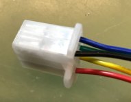
Here is how the hall sensor connector looks on the controller side. It has 5 pins, including ground and 5v. Halls need both to operate.
I'll fix the diagram to make it clear.


hall_connector.JPG

MJSfoto1956 said:
On a somewhat related theme, my current Chinese eScooter/eMoped comes with an anemic QS205 2000w 12" hub motor which I plan on upgrading (after first upgrading my controller) to a QS273 8000w 13" hub. There are five wires that constitute the "Halls" connection on a 273 series. But the PowerVelocity wiring diagrams (that I could find) only show three wires connected to the motor. Do I leave these two additional wires unconnected? If not, where do they go?

See my attached wiring diagram below.
 
Powervelocity.com said:
Here is how the hall sensor connector looks on the controller side. It has 5 pins, including ground and 5v. Halls need both to operate.
I'll fix the diagram to make it clear.

Perfect! Thanks a lot.
 
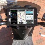
There is no such thing as my navigation. The app is actually using Google maps. So, I am just trying to understand the use scenario that would necessitate this. However, split screens are supported in Android starting from Nougat version.

MJSfoto1956 said:
Yes it is a mockup. But the main point was not your navigation vs. Google. The main point was has anyone attempted to use "side by side" apps horizontally on an Android tablet on their bikes?

M
 
I would also like to know how this can be done . ( side by side apps horizontally on a Android Tablet )
More interesting to me is to use a sport camera that connects to the Android Tablet by way of Wi-Fi , and the image is viewed on the tablet.

This works not only as a way to record cars coming up behind you, it also functions as a rear view mirror . This is Much better than constantly turning your head back to see how close traffic is near to you . And / Or to see if there is a clear road behind you.

MJSfoto1956 said:
Yes it is a mockup. But the main point was not your navigation vs. Google. The main point was has anyone attempted to use "side by side" apps horizontally on an Android tablet on their bikes?

M
 
MJSfoto1956 said:
Powervelocity.com said:
Protecting from what? Unless you submerge it in water, it should be fine.

I live in an area that is close to the ocean and I have come to discover that electrical connections exposed to the salty air around here deteriorate appreciably (I'm not even talking about going to the beach!). I also believe we here in New England are experiencing a noticeable increase in acid rain since ...

Turns out that when the surf tosses salty froth into the air it evaporates and leaves salt nanocrystals floating around in the breeze, and they can travel for miles, depositing a film of salt onto the connections which pulls water from the air and promotes oxidation very efficiently. Coating the connections with appropriate grease or spray should help, but the real solution is to move away from the natural corrosion generating machine, it will affect everything in it's path. (Acid rain is not even required). :)
 
Powervelocity.com said:
There is no such thing as my navigation. The app is actually using Google maps. So, I am just trying to understand the use scenario that would necessitate this. However, split screens are supported in Android starting from Nougat version.

Well for one, many people prefer WAZE instead of Google maps, so I could imagine using your app for the speedometer/battery SOC and WAZE for traffic in a side-by-side orientation. There are plenty of other use cases, such as the rear video scenario suggested by another poster. Again, was just curious if anyone had actually implemented it on their ride. Seems like a good feature to have for any ebike.

M
 
So I'm ready to pull the trigger on purchasing a PV 20kW controller mated to a QS 8k 273 hub motor. I just need confirmation that the below diagram is accurate for my application. In particular, I'm a bit unclear about how to wire the QS motor temp sensor -- I'm assuming that the two silver wires (one from Hall plug #1 and one Hall plug #2) should be used as input into the bluetooth module as I can't imagine that QSmotor installed two separate temp sensors within the hub. Any input appreciated.

43464028080_df52a29b7a_o_d.jpg


Michael
 
That's a very neat diagram! Thank you for putting it together, Michael. Great help for other people as I have been shamefully neglecting updating the documentation being busy with the software development.

All looks good. As an option, you may want to run the 12v DC/DC through the ignition as that would ensure all your accessories are turned off when the ignition is off. That's of course, if your 12v load is not too heavy and the ignition switch can handle it (normally < 3A or so for a simple key switch).

The temperature probe uses the common ground with the hall sensors, hence, one wire is enough. You would want to connect the white wire from the hall bundle that is connected to the controller (not the spare). However, when or, rather, if you ever have to switch to the spare halls, you will want to switch to the other temperature output that comes with it as well.

I have a few customers that have run the 273 with the controller for a long while. They have been very happy with the performance and reliability.
 
Powervelocity.com said:
The temperature probe uses the common ground with the hall sensors, hence, one wire is enough. You would want to connect the white wire from the hall bundle that is connected to the controller (not the spare). However, when or, rather, if you ever have to switch to the spare halls, you will want to switch to the other temperature output that comes with it as well.

So I'm a little unclear on that point. Are you saying that your Bluetooth module only requires a single wire from the motor temp sensor (in the case of QS the silver wire)? Or does your Bluetooth module require both the silver and common ground from the non-spare halls connector?

Thanks!
Michael

P.S. I updated the diagram to reflect my current understanding
 
Powervelocity.com said:
All looks good. As an option, you may want to run the 12v DC/DC through the ignition as that would ensure all your accessories are turned off when the ignition is off. That's of course, if your 12v load is not too heavy and the ignition switch can handle it (normally < 3A or so for a simple key switch).

So that brings up an interesting question -- does the Vcc circuit work with any voltage (e.g. 12V)? I kinda thought it had to match the primary input voltage (e.g. 72V).

Michael
 
The module shares ground with the controller and motor hall sensors. That's why it's called common.
Therefore, you need only the silver wire from the non-spare hall connector. The ground is fed in the module via the the programming and/or the CA connector.

MJSfoto1956 said:
Powervelocity.com said:
The temperature probe uses the common ground with the hall sensors, hence, one wire is enough. You would want to connect the white wire from the hall bundle that is connected to the controller (not the spare). However, when or, rather, if you ever have to switch to the spare halls, you will want to switch to the other temperature output that comes with it as well.

So I'm a little unclear on that point. Are you saying that your Bluetooth module only requires a single wire from the motor temp sensor (in the case of QS the silver wire)? Or does your Bluetooth module require both the silver and common ground from the non-spare halls connector?

Thanks!
Michael

P.S. I updated the diagram to reflect my current understanding
 
VCC on the controller must be the battery voltage (60-84v in your case). It's using the battery voltage to trace the over and under voltage. If you feed 12v into the controller ignition, it will not work. What I meant is that you could power the 12v DC/DC adapter from the ignition wire, so that when the key switched is off, the 12v circuit would also be off.

MJSfoto1956 said:
Powervelocity.com said:
All looks good. As an option, you may want to run the 12v DC/DC through the ignition as that would ensure all your accessories are turned off when the ignition is off. That's of course, if your 12v load is not too heavy and the ignition switch can handle it (normally < 3A or so for a simple key switch).

So that brings up an interesting question -- does the Vcc circuit work with any voltage (e.g. 12V)? I kinda thought it had to match the primary input voltage (e.g. 72V).

Michael
 
Powervelocity.com said:
VCC on the controller must be the battery voltage (60-84v in your case). It's using the battery voltage to trace the over and under voltage. If you feed 12v into the controller ignition, it will not work. What I meant is that you could power the 12v DC/DC adapter from the ignition wire, so that when the key switched is off, the 12v circuit would also be off.

So I have updated the graphic (see earlier post) with your new information, could you please review to see if all is now correct?

Thanks!
Michael

P.S. if you supply me with a high-res version of your "Motor Phase and Hall Combos" comparison chart, I'll add it to my diagram and it won't stick out like a sore "lo-res" thumb anymore.
 
Hi, received improved version of the app nice work. But i have 2 dislikes where is odo?? After 1st app update my odo was reset, then after latest new look update odo is yotaly gone! 2nd i would love to see voltage calibration option, i have very accurate volt meter my full charge voltage is 100.8v app shows 101.6v
 
Odo will be re-added in the next maintenance release. It's still counting, so no data would be lost.
Voltage calibration will be added as well.

Rs.Anton said:
Hi, received improved version of the app nice work. But i have 2 dislikes where is odo?? After 1st app update my odo was reset, then after latest new look update odo is yotaly gone! 2nd i would love to see voltage calibration option, i have very accurate volt meter my full charge voltage is 100.8v app shows 101.6v
 
Is there a way to reset the odo? There was a period a while back where the odo was going whether I was actually moving or not. I suspected some sort of halls issue but before I did anything it just started working correctly. The bummer part is my controller reads like I put over 57,000 miles on it. My CA and GPS both read closer to 1400.
 
Yes, you can go to Settings, scroll all the way down and Hit Reset Odo Button.

dirttorpedo said:
Is there a way to reset the odo? There was a period a while back where the odo was going whether I was actually moving or not. I suspected some sort of halls issue but before I did anything it just started working correctly. The bummer part is my controller reads like I put over 57,000 miles on it. My CA and GPS both read closer to 1400.
 
So how much power is consumed by a 20kW PV controller when the Vcc is switched off, assuming the main power is hooked up directly to the battery pack without any additional switched circuitry?

I.e. what does it take to maintain the caps at full charge when the rest of the PV controller is otherwise off?

M
 
Depends on the design and components used, but if capacitor leakage is minimal, and it has no resistors across them to drain them when not in use, it's probably in the microamp range. You can measure your particular controller to verify it's actual consumption.

Note that as the caps age, their leakage current can go up, but it is still generally pretty small.
 
I haven't measured it as this was never a concern but based on observations, no perceptible drain from the controller.


MJSfoto1956 said:
So how much power is consumed by a 20kW PV controller when the Vcc is switched off, assuming the main power is hooked up directly to the battery pack without any additional switched circuitry?

I.e. what does it take to maintain the caps at full charge when the rest of the PV controller is otherwise off?

M
 
Status
Not open for further replies.
Back
Top