Halls sensors giving strange voltage reading across blk to signal wires

newbiehere

100 mW
Joined
Oct 8, 2018
Messages
46
I post this in Motor Technology, apologies for that, its better posted here

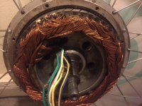
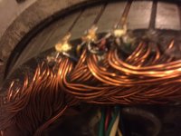
I have an older Chinese made 36 volt 350 watt brushless motor that has suddenly stopped working. I tested the halls supply red/blk and got 6.5 volts but between ground (blk) and yellow blue or green signal wires I got 13.5 volts. One of the halls appears to be facing down, the 2 on the sides up. what would give me such a reading? Is one of the halls open..or since one is facing down, its acting as a voltage doubler? is this normal? You can see in the attached pic that the middle halls 5V is on the end (right side) like its been flipped over and bridged to the rightmost halls, on the normal leftmost lead.

I have ordered the honeywell ss41 as replacements.

also, can one change the cap value on the board to a higher rating to put in more voltage, or is it more involved than that?

and..how does one test the phase wires for output? just put the voltmeter lead in one phase wire hole and the other to ground?
 

Attachments

  • IMG_6401.JPG
    IMG_6401.JPG
    60.7 KB · Views: 1,792
  • IMG_6402.JPG
    IMG_6402.JPG
    48.6 KB · Views: 1,792
The 13.5v is coming from the controller. Each signal line is pulled up by a resistor and the hall switch pulls it to ground when active. The hall power can be a different voltage as long as it's within the specified range. SS41 are rated for up to 24v.

As long as the hall signals toggle between the high value (13.5v in your case) and near ground as the magnets are moved, then it's good.

Bad halls will be stuck high or low and not change with the magnet position.

The upside down sensor simply reverses the output with respect to the magnet polarity. This is pretty common. It allows the sensors to be spaced closer together for easier assembly.

To run a higher voltage, you need to check the main caps, the FET ratings, and the voltage regulator. FET ratings are easy, just look up the part number. Voltage regulators vary depending on design. On the older cheap controllers, there is typically a big power resistor that needs to be changed for higher voltage.

Not sure about your question on the phases. You can't really measure the output of the controller without a motor. It can be done but it's not easy. You can test the motor by spinning it and shorting pairs of phase wires. Spin with no connection, then spin with any pair shorted and see that it greatly increases the resistance to turning. Repeat with other combinations of phase wires. All should be similar. A burnt or open phase wire will make no change in resistance. Shorted windings will cause it to be hard to turn even with the phase wires disconnected.
 
Thank you for your fast reply. So between red and black, 6.5 is normal? I have the phase wires disconnected. When I spin the wheel, there is a voltage change from 13.5 to 5 for ex., but I dont see it go to 0 where is the 13.5 coming from, if supply red is only 5?

I was having trouble with the halls throttle. sometimes the motor would spin, othertimes nothing. Im awaiting a new throttle. could the burned halls in my throttle be causing this? when the throttle wires (3) were disconnected, the motor would spin, seems the halls controller pins were floating, so I got movement, now nothing
 
oh your saying that the signal wires are being pulled up to 13.5? why such a high voltage and not 5 V?

I will check the controller harness terminals to see if there is 13.5 to ground without the motor halls harness connected
 
Also if I may ask, there are 3 phase wires, going to each respective coil I suspect in wye configuration...where is the return wire? there are 2 female connections and 1 male on one connector and reverse that on the other.

and the large cap, is that a filter cap? I have read that its what limits the voltage rating for the controller
 
yes your right; on the controller, the black and signal wires give 13.5 readings, pulling them up to a supply, just dont know why they use a different supply rail than the 5v, perhaps a higher voltage is needed for a signal back to the controller?

Also, I crossed the wires on my halls throttle due to some color mismatch, is there a way to t-shoot the throttle output without using the halls throttle? (awaiting new one to arrive) I mean like with a variable pot? seems the motor halls are ok, FETS are all good, Im hoping the only issue is the burned halls in my throttle twist type
 
Yes you can test the throttle input using a pot. Anything from 5k to 20k should work for a test. Many controllers will sense a fault condition if the throttle signal voltage is outside of the normal range (typically 0.5v to 4.5v). If the pot is all the way to zero, it may not work. The trick is to dial the pot up to about 0.8v then recycle the power to the controller so it resets the fault.

I don't know why they use the 13.5v to pull up the hall signals on some controllers, but there is no reason it won't work. Maybe it gives better noise immunity. The 13.5v supply is also used to drive the FET gates and typically feeds the 5v regulator.

The phase wires each can act as a supply or return. At any time in the commutation cycle, there is one phase positive, one negative, and one floating. This constantly changes as the motor rotates.

The capacitor voltage rating is only one thing that limits the voltage. The FET ratings and the voltage regulator rating are the other main ones. These can generally be determined by looking at the part numbers.
 
Thanks again for the informative reply. So, if the controller halls control 3 pins are disconnected (no controller or faulty halls) then the motor will not spin under any condition? I hope this was my problem

for the pot test, I should connect one terminal to the controller 5 V, one terminal to the ground and the wiper to the signal out from the controller?

I see there are 6 mosfets so at any time 2 are being used? One for positive and one for negative?
 
To clarify, your throttle only has one hall sensor. It varies the regulated input supply voltage of ~ 5vdc to between .8 and 3.5 vdc of output to the controller.

On re-reading perhaps your referring to type as opposed to plural... Then it's just me. :lol:

For more in depth on how it works, troubleshooting, and different methods of testing a controller without a throttle see this thread... :!:
 
great stuff thanks for the tutorial link

so if the controller locks out due to my missmatch color wiring short...does it auto reset if all 3 terminals (in my case 3) are removed?

" which will automatically reset when the throttle is returned to the full off position"

-----------------------------------------------------------------------------------------------------------------------------
using the pot was able to get the motor to turn, 120K pot, either on or off it seems but at least I got it narrowed down to the halls in the twist throttle
 
newbiehere said:
" which will automatically reset when the throttle is returned to the full off position"


This was specifically referring to an unusual throttle output with it wired correctly, like Fechter was mentioning with the pot test. I have not tested what would happen with a mis-wired throttle. As the thread is for preventing that. :wink: But if you have 5vdc on the throttle supply input, as your pot test indicates. You should be good to go. :)

So you did actually have 13.5vdc on the motor hall sensors Red and Black wires?

And surely you properly insulated those poor nicked and damaged wires going into the motor...
 
newbiehere said:
Thanks again for the informative reply. So, if the controller halls control 3 pins are disconnected (no controller or faulty halls) then the motor will not spin under any condition? I hope this was my problem

for the pot test, I should connect one terminal to the controller 5 V, one terminal to the ground and the wiper to the signal out from the controller?

I see there are 6 mosfets so at any time 2 are being used? One for positive and one for negative?

Yes on the pot test. If the zero position causes a fault, you can cheat by turning the pot up just slightly before turning on the power.

Yes on the FETs. Two are on at any given time, one high side and one low side. These switch depending on rotor position.

If either the motor hall or the throttle are giving an invalid signal, the controller won't power the motor.
 
yes everything is insulated, redid all that assembly. Im getting rotation with the pot, kind of on/off no range but its ok now, so I will await my halls throttle and replace.

I would like to change out the embeded halls in the rotor to the type you see mounted on the side on a ic board, wonder if that is possible? Just seems an easier way to replace the halls sensors if they go bad instead of digging them out of the milled slots on the rotor, guess the mfgs changed the config later.

On my supply side of the halls, I get 6.5 V, not 13.5, the 13.5 is only between grd and the signal wires

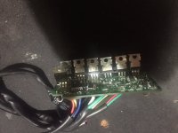
I have a 48 volt UPS battery set I got for free, Ive read that UPS batteries are deep cycle, and I charge the the set with the UPS box, at 52 volts to push in the 48V at the high end of the charge I guess, and for my 36 v I remove one battery later, a bit of a pain as the box or tray is designed to hold 4 batteries. If I changed the cap rated at 50 V on the controller, and possibly the mosfets could I use the 48 Volt battery set? I cant find a voltage regulator like a 7805 etc on my controller. I see 6 IRF 3205 transistors rated at 55V, and one Fairchild E-13005-1 transistor on the flip side of the controller (dont know what that one does, please see attached picture, also, the large cap, how does it limit voltage?)

"Yes on the FETs. Two are on at any given time, one high side and one low side. These switch depending on rotor position."

so Im guessing this is software that tells the controller when to fire the next winding? the magnets rotate past the halls, and that signals the controller? would be interesting to make a controller but Im sure its complex when it comes to brushless motors

Thanks for all your advice.
 

Attachments

  • IMG_6428.JPG
    IMG_6428.JPG
    41.2 KB · Views: 1,672
The existing caps and FETs look to be designed for 36v systems. At 48v battery might be 54-60v coming right off the charger. The parts need to be rated for a little more than what you are running to have some "headroom" for voltage spikes. If not enough, then it just blows up.

The E-13005 is part of the voltage regulator. The transistor is rated for 400v, so not even close there, but the other parts that drive it may not have enough rating. Many times these are unmarked tiny transistors that you can't look up the data for.

Controllers in this power range are incredibly cheap these days, so it would probably save you some money and a lot of work to just get one designed for 48v.

The hall sensors in the motor are generally very reliable unless the motor drastically overheats or if the wiring gets damaged and they get backfed with the wrong voltage. Having a little board for the halls doesn't really make changing them much easier as this all gets glued in place.
 
I checked the halls sensors, seem to be triggering and changed the twist grip throttle. The problem now is that the riding range is very short, using an UPS battery set (12 volts/5aH each x 4). I charged the 48 volt set to 100%, but later, noticed that one of the batteries was at 8 volts, the other 3 at 12. could a damaged battery cause such a short range? the system is designed for 36 but with 3 connected, had very limited power, dropped in the other battery for 48 volt, lots of initial improvement but soon power went down again.

I used the 3 LED light tester for the halls, at any given time during wheel rotation, 2 halls will light, then only one, then 2 on, then one..is this a normal good result for this test?
 
newbiehere said:
could a damaged battery cause such a short range? the system is designed for 36 but with 3 connected, had very limited power, dropped in the other battery for 48 volt, lots of initial improvement but soon power went down again.

I used the 3 LED light tester for the halls, at any given time during wheel rotation, 2 halls will light, then only one, then 2 on, then one..is this a normal good result for this test?

The hall signal test is good. There should never be all or none lit. Always 1 or 2.

The batteries sound like trash. Even new lead acid batteries are pathetic. Good enough for you to test that the rest of the system is working but you will never get decent range out of lead batteries. These days you can get a good lithium battery for only slightly more than what a new lead-acid set would cost. And it will last much, much longer.
 
Ok will conclude for now that the motor, halls, throttle and controller are good

are NiCad batteries, like 12 volt 6 aH wired in series (cordless drill types) an option?

or motor cycle batteries?

thanks for all your help!
 
People have used lithium power tool batteries before. Any nickel chemistry is pretty poor long term.

Years ago I used to run lead acid batteries that were removed from medical equipment. Still in good shape most of the time, but lithium batteries are soooo much better.

If you're super cheap, you can scavenge dead tool packs and try to find enough good cells to make a pack. Many times they get recycled when there is just one bad cell. New packs from the right place can be fairly inexpensive.
 
Yes, I removed the bad battery @ 8+ volts, put in a set of lead acids 12 v x 3, range was extended but still rather poor, around 6 km, then the set was at 34 volts not under any load. I dont know what the low end is for a 36 Volt set but Im guessing 34 volts is not ideal.
 
On most there is a way to change the cutoff voltage, either in programming or by changing a resistor or jumper on the board somewhere. It should be possible to lower it. A 36v nominal setup should be cutting off somewhere around 30v or less. 34v would be pretty high.
 
Thanks for your reply; the controller is not cutting out at 34 volts, just loss of power at that level
 
"change the cutoff voltage, either in programming"

how would one access the programming? I would need the same compiler cable etc correct?
 
Most programmable ones use a USB to TTL232 cable and some app that runs on a laptop. Newer ones use Bluetooth and a phone app. You need the right app to make it work.

Hardware hacking might be the only way on that one. If the picture of the board was a little better, I might be able to see where it's done. Many have a jumper spot on the board to change settings.
 
Yes there is currently a J1 solder bridge being used on this board, and J2 is left open or not bridged; dont know if those are the jumpers your talking about

the controller is not cutting off at 34 V, just loss of power

If I may ask, during Halls LED light test, as I mentioned before, at any given time I found that 2 Halls are on during the wheel rotation. why is that? what does the controller do with two Halls pulled to ground signal? Thanks for any information.
 
The hall signals will be on half of the time and off half of the time (this is because the magnets are equally sized and alternate from north to south). But in a 3 phase motor, the timing has to overlap, so there will be times when two are on. Here's a pretty good description. Look for the graph of hall signals.
https://www.digikey.com/en/articles...-most-effective-way-to-commutate-a-bldc-motor

The controller probably drops power in an attempt to give you some warning before it cuts off completely. The cutoff point will still be based on the same voltage measurement.

On your controller, there is a skinny "ignition" wire that gets connected to the B+ to turn on the controller. If you trace this wire to the board, the spot of interest will be connected to it by a trace. If there is no jumper, there will be a resistor on the board that could be changed to lower the cutoff point.
 
Back
Top