
You are using an out of date browser. It may not display this or other websites correctly.
You should upgrade or use an alternative browser.
You should upgrade or use an alternative browser.
Bafang ultra upgrade to 2500watt
- Thread starter jpc6000
- Start date
Daxxie
100 W
- Joined
- Feb 14, 2017
- Messages
- 133
jpc6000 said:when I turn the cranck, does the engine have to start?
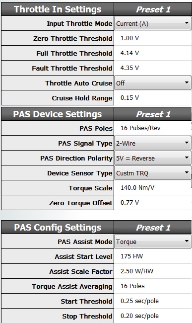
Depends on your PAS settings in CA3.
Very cool thread.
Two things though..
Bafang has a history of underbuilding things. You might see a wonderfully huge stator here, but i'd bet the drivetrain is not as tough.. i would run a low phase amp to battery amp ratio. This means you want low initial torque. Program the controller to give more of a flattish torque response vs one with a strong peak in it, and you can help protect the drivetrain from extra stress. Us geared motor guys have been using that trick to boost power without destroying those nylon gears for a long time..")
Secondly, consider heatsinking the phaserunner to the case very very well. The phase runner can go into temperature limiting at high power without additional heatsinking and air flowing through it. Here, you're sharing the motor heat and the controller heat in the same space and air is not helping you much unless you thermally link the controller to the outside case. I would use those bolt holes on the phaserunner and some copper shims and maybe even thermal paste to create a thermal link between the phaserunner and the bafang case... at a minimum!
Best wishes on this project!
-nep
Two things though..
Bafang has a history of underbuilding things. You might see a wonderfully huge stator here, but i'd bet the drivetrain is not as tough.. i would run a low phase amp to battery amp ratio. This means you want low initial torque. Program the controller to give more of a flattish torque response vs one with a strong peak in it, and you can help protect the drivetrain from extra stress. Us geared motor guys have been using that trick to boost power without destroying those nylon gears for a long time..
Secondly, consider heatsinking the phaserunner to the case very very well. The phase runner can go into temperature limiting at high power without additional heatsinking and air flowing through it. Here, you're sharing the motor heat and the controller heat in the same space and air is not helping you much unless you thermally link the controller to the outside case. I would use those bolt holes on the phaserunner and some copper shims and maybe even thermal paste to create a thermal link between the phaserunner and the bafang case... at a minimum!
Best wishes on this project!
-nep
Daxxie
100 W
- Joined
- Feb 14, 2017
- Messages
- 133
jpc6000 said:I have change nothing in CA configuration
What is standard?
With the Torque sensor correctly wired and these settings your motor should engage when you turn the crank.
Don't forget the 20.000Ω resistor between PAS and GND
devo1223
100 W
Ivanovitch_k said:

Sorry I'm not very electrically inclined. Is that an IPM motor I'm looking at? Does anyone know if the BBHD is as well?
devo1223 said:Ivanovitch_k said:Sorry I'm not very electrically inclined. I IPM ms that anotor I'm looking at? Does anyone know if the BBHD is as well?
I don't think that is that an IPM motor. Why do you ask?
Daxxie
100 W
- Joined
- Feb 14, 2017
- Messages
- 133
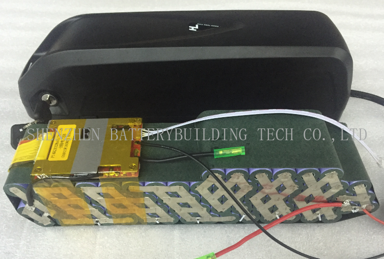
jpc6000 said:And some pictures, how that you squeeze 70 18650 battery's in the case.
Finding a 17S 50A BMS that will fit the case... won't be easy.
Cell layout:
You can find these pics online:
But this layout will NOT fit a Jumbo shark case (Hailong 2)
The top row of 6 cells has to move 1 cell to the right.
And you can not use the switch and the USB plug that come with the case.
Layout should be like this.
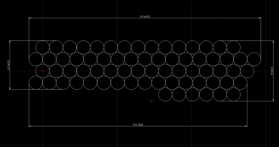
But the spacing between cells has to be very accurate.
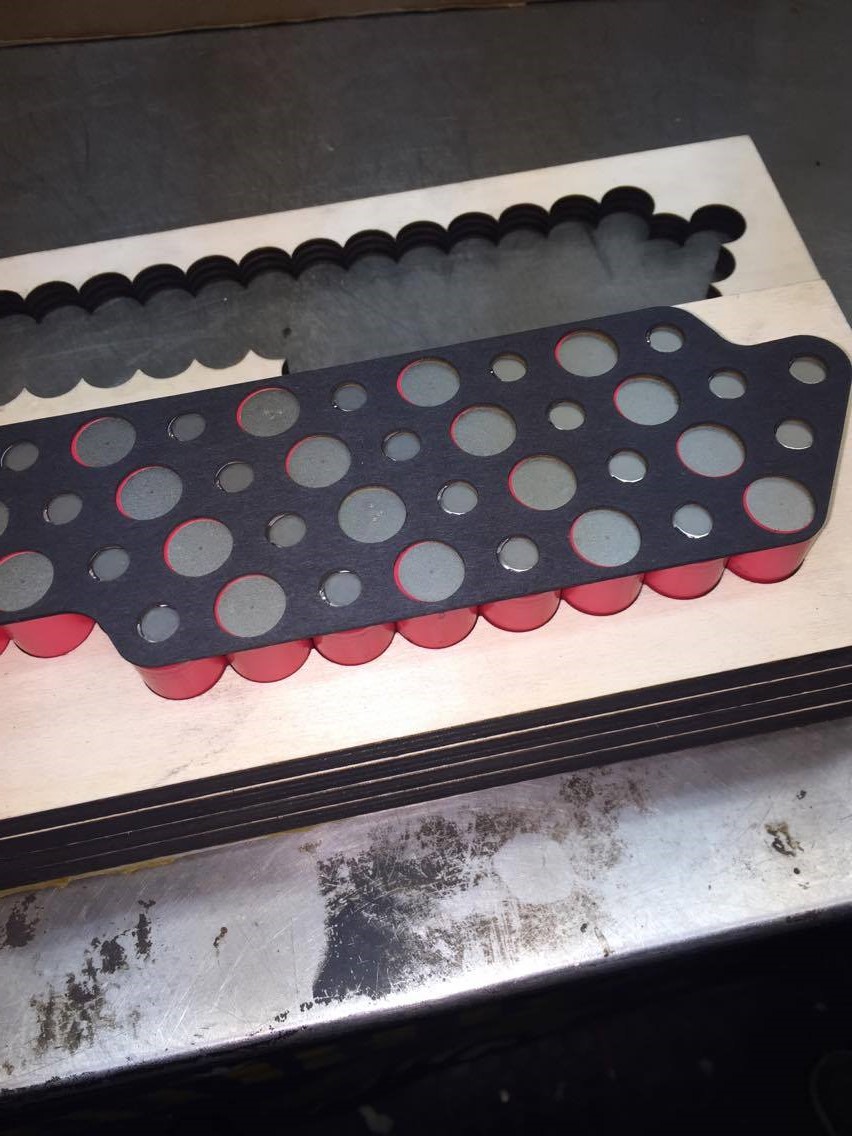
I always make a mold first with my CNC router to make sure the cells are correctly glued.
Picture of a 14S4P mold.
I used the Hailong switch to power up my Phaserunner.


Daxxie
100 W
- Joined
- Feb 14, 2017
- Messages
- 133
jpc6000 said:I have found a BMS with good dimensions I think
but it's not a smart BMS
What power are you aiming for?
On the previous page you said:
jpc6000 said:This should be for me better, than I can use 72V ...
the 17S 100A Smart EV li ion battery PCB board Bluetooth Mobile BMS for 71.4V Li-Ion 18650
And the battery SAMSUNG INR18650-35E UNPROTECTED 3500Mah /13A max
17x4=68 battery's
Samsung INR18650-35E only has a continuous discharge of 8A
Nominal voltage is 3.6V so a 17S gives 61.2V nominal.
A 17S4P Will give you 61.2V with a continuous discharge of 32A = 61.2x32 = 1.958Watts (827Wh)
You should go for the Samsung 30Q with a continuous discharge of 15A and a 50A BMS 61.2Vx50= 3.060Watts (724Wh)
or if you want a bit more range: 14S5P Sanyo NCR18650GA continuous discharge of 10A 52Vx50= 2600Watts (912Wh)
TorEddy
100 W
From exess-bikes:
The only problem is the controller because Bafang has made several versions which are not compatible. But we are currently developing our own controller which will be much more reliable, more efficient (higher range), better software, better protection. It will be available end of 2018. It fit in the place where the Bafang controller is mounted, so it just replaces the Bafang Controller. It comes with all bikes from January 2019 and it will be available as an aftersales part as well. So the customers having already an EXESS bike can use this controller also.
Will you be able to run more than 30A through the new controller?
yes we will be able to run more than 30A. I don’t know yet how much current we will enable, this needs to be determined.
pas not working
I have change config ca to your info.
But its not working?
In config pas I see only second bar go up and down
the other do not change!
this is two wire torque pas, so something is wrong!
PAS->SensrType identifies the interface as either 1-Wire (Dir) or 2-Wire (Dir+RPM). Proper setting may be determined by going to the SETUP PAS SENSOR screen, rotating the crank, and seeing if one or both of the 'P' and 'D' arrows alternate up and down. If one, it is a 1-wire sensor, if both it is 2-Wire.
Whats wrong?
Daxxie
100 W
- Joined
- Feb 14, 2017
- Messages
- 133
jpc6000 said:pas not working
.............
Whats wrong?
Did you install a 20K resistor?
Daxxie
100 W
- Joined
- Feb 14, 2017
- Messages
- 133
jpc6000 said:yes I did
Well difficult to tell from a distance
I only live an hour and a half away from you so if you really can't solve it feel free to come over and I will have a look.
.jpg")
.jpg")
Daxxie
100 W
- Joined
- Feb 14, 2017
- Messages
- 133
Looks like the same problem I had untill I installed the 20K resistor.jpc6000 said:Torque sensor still not working
Pas signal ok
but in CA setup pas device D go up and down but P not?
Are you sure you added a resistor?
Tell me how you connected it, or do you have a picture?
.jpg")
I have ask Grin about the problem, they answer:
In a pinch you can always just switch the P and D signals, since in principle only the P is needed for PAS to work.
I'm not at all familiar with the actual sensor signal levels of that product, but a volt meter will tell you what is going on. You just need to sort things out so that the CA's PAS input lines are toggled between 0V and 5V. Obviously in your current setup they aren't or you'd see the signal toggle.
when moving cranck
pas / gnd switch between 0.782v and 2.4v
Pas shift / gnd switch between 4.29v and 1.4v
Gnd and Speed/Dir 0.7v back and forwards nothing change
Gnd and Torque 70mv back and forwards nothing change
this is not the same what Daxxie messure!
On the back of the print stays
ZL1/ZL2/5V
DS/LJ/GND

pas / gnd switch between 0.782v and 2.4v
Pas shift / gnd switch between 4.29v and 1.4v
Gnd and Speed/Dir 0.7v back and forwards nothing change
Gnd and Torque 70mv back and forwards nothing change
this is not the same what Daxxie messure!
On the back of the print stays
ZL1/ZL2/5V
DS/LJ/GND
Daxxie
100 W
- Joined
- Feb 14, 2017
- Messages
- 133
jpc6000 said:when moving cranck
pas / gnd switch between 0.782v and 2.4v
Pas shift / gnd switch between 4.29v and 1.4v
Gnd and Speed/Dir 0.7v back and forwards nothing change
Gnd and Torque 70mv back and forwards nothing change
this is not the same what Daxxie messure!
Well you have the 20K resistor installed so its normal that your PAS / gnd signal is lower then mine which was measured without a resistor.
Pas shift looks good.
Dir you do not need.
Torque you can not measure with simply rotating the crank.
You need pressure on the pedals.
You would have to install it on a bike and pedal to actualy measure it or hold the chainweel with a vice grip and apply pressure to the pedal.
So all those values look pretty good.
This is what Justin from grin technologies write about the problem
when moving cranck
pas / gnd switch between 0.782v and 2.4v
That's not really enough for a reliable digital signaling. Really you want <1V and >3.5V for proper logic level signalling.
when moving cranck
pas / gnd switch between 0.782v and 2.4v
That's not really enough for a reliable digital signaling. Really you want <1V and >3.5V for proper logic level signalling.
Similar threads
- Replies
- 0
- Views
- 363
- Replies
- 16
- Views
- 513
- Replies
- 12
- Views
- 10,610