Lurkin
100 kW
Interesting. Is that an app on your phone allowing you to do that heat imagery?
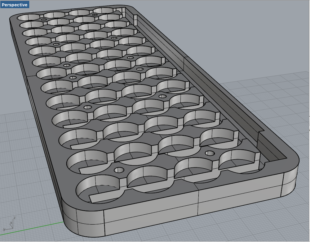
I'm planning to use the material as some what of a spring, in order to compress my battery contacts together.
bzhwindtalker said:I calculated the deformation in the middle of the pack, it should be OK especially for the 10S6P (calculated for a 8S10P version)
The springs can compensate the middle deformation of the holder. There is a balance of clamping force to spring rate to find to make it work with a specific configuration and holder material. The spring travel is around 2.4mm and here the deformation is max 1mm, also this is with V1 springs with higher force, I reduced the springs force since this calculation.
Ecyclist said:Here is my final product. It is 10S6P with twin charging capability. I can charge it bulk with 42V charger, or I can balance charge it with SKYRC iMAX B6AC hobby charger. I can control amps. with VESC and I monitor cells with small volt meter and two battery testers / loggers.
I use XT-90 Anti-Spark Connector for bulk charging and power delivery and two XT-60 connectors for balance charging. The pack contains a fuse that doubles as a kill switch.
Thanks dude.MJSfoto1956 said:Ecyclist said:Here is my final product. It is 10S6P with twin charging capability. I can charge it bulk with 42V charger, or I can balance charge it with SKYRC iMAX B6AC hobby charger. I can control amps. with VESC and I monitor cells with small volt meter and two battery testers / loggers.
I use XT-90 Anti-Spark Connector for bulk charging and power delivery and two XT-60 connectors for balance charging. The pack contains a fuse that doubles as a kill switch.
That is a stunning piece of design and superb execution. A+
(you should sell this kit!)
Quick question: why two XT-60 connectors for balance? Are you using two hobby chargers in parallel? (i.e. charging either 5s6p or 10s3p each?)
M


bzhwindtalker said:The spring travel is around 2.4mm and here the deformation is max 1mm, also this is with V1 springs with higher force, I reduced the springs force since this calculation.
patrickb said:The bus plates are 0.5mm. I soldered nickel plated contacts onto them. The build still lacks of a housing.
Solder is a horrible conductor and will cold flow over time.markz said:Why not
1) a mound of solder for the contacts and compress each end plate?
or 2) a dimple and something behind it to keep it from crushing?