Bafang G310 geared hub - 11:1 reduction ratio!!!

This is just a guideline based on the ol' trusty rusty infineons. Adjust to taste for a modern FOC controlled world and what parameters do similar things in a FOC ( IE create a relatively flat torque curve )

How much continuous power a geared motor can take w/o melting is another concern that's separate from that.
There is no temp sensor to save your ass from an overheat on this motor, so tuning that aspect will be a process of monster hill > stop > feel the motor heat > cool down if too hot and bump the power down when you get home, etc.

Will update with what my tune is on an infineon clone and phaserunner is.. using a 700c wheel standard speed motor on 52v.
 
davideserin said:
Is it possible to put a temp sensor in this motor?

There's an easy way to do this if you're willing to forego the internal speedometer sensor. Just open up the motor and remove the white wire from the speed sensor PCB, and instead wire it up to a grounded thermistor or other temperature sensor. Or tap it in right where the original speedo hall sensor is located as I did here:

G310_ThermistorMod.jpg

although in this case IIRC there was also a pull-up resistor on the hall PCB that I had to remove so that the CA3 would report an accurate temperature.

If you have a CA3 device, this signal goes up to the display via a yellow wire to the CA3's speedometer input pad. So you can then desolder it from there and move the yellow wire to the temperature/thermistor input pad instead and have temperature sensing with no extra cables or wires at all, and if you want a speedometer again just hook up a normal spoke magnet wheel sensor to the CA3.

The other possibility is to run the motor sensorless and then repurpose the hall signal wires for your temperature probe, or if you are crafty you can feed additional small gauge signal wires beside the motor cable as I did here with the blue and black wires:

View attachment 1

(this was part of an experiment to use statorade for bridging heat from the stator to the motor shell with external magnets on the shell to hold the fluid in place)
 
justin_le said:
(this was part of an experiment to use statorade for bridging heat from the stator to the motor shell with external magnets on the shell to hold the fluid in place)
Hey Justin, can you tell us more about thsi experiement? Sounds interesting!

or if you are crafty you can feed additional small gauge signal wires beside the motor cable as I did here with the blue and black wires
I'm assuming you'd have to remove the potting around the motor cable to do this, right?
 
Hm.. kind of a process.

How'd she do with ferrofluid, Justino?
I just got my wheel in today from you guys ( great packing job! ) and am excited to put some miles on this cute little thing soon.
 
neptronix said:
How'd she do with ferrofluid, Justino?

Not much of an effect from my first try, I posted a bit of info here
https://endless-sphere.com/forums/viewtopic.php?f=2&t=48753&p=1363439&hilit=G310#p1363439
but didn't include any quantitative numbers since I wanted to revisit it a bit more thoroughly. My recollection is that it was less than 10% thermal improvement but that's just from a first stab.

As I mentioned in that post, I think you could be quite successful using just a regular oil cooling in these motors without even needing a ferrofluid. There would just need to be enough coolant to bridge a section of the thin gab between the hub shell and the fixed stator, and given the small diameter of this hub shell that shouldn't result in much viscous drag. The beauty of an inrunner for a geared hub like this is that you don't need any coolant at all in the high speed rotor air gap, just at the much lower speed shell to stator gap.

I might have a chance to run that test this weekend and find out for sure if there's merit to liquid cooling on the G310's. Empirically, they seem much more prone to hit mechanical limits (ie stripped gears) when pushed, than thermal limits (ie burnt windings). In fact I don't think we've seen a single instance yet of cooked windings with this hub model. But even if that's not a main failure mode, a cooler motor is always a happier and more efficient motor, and the nylon gears are mechanically stronger when cool too.

I just got my wheel in today from you guys ( great packing job! ) and am excited to put some miles on this cute little thing soon.

Sweet. For me at least, the smooth/quiet helical gears are a game changer in the relative appeal of small hub motors like this. I'll be curious to hear your take on it too compared to the Outrider geared hub you had previously.
 
Interesting, yeah i understand that the gears and the built in torque arm design are a limiting factor for making a lot of power.

I think though that it would be realistic to tune the controller for a flat phase response to save the gears. If you run this motor on a roadbike with drop bars and pedal, you could see 30mph continuously with ferro fluid or some other kind of motor fill being used to act as an insurance policy for when hills and stop 'n go start creating a lot of heat..

Of course on a mountain bike with an upright position, you won't see such great results because air drag will bump up your watts too high. 26-27mph continuously seems like a more reasonable expectation.

Example of the roadbike scenario on the simulator:
https://www.ebikes.ca/tools/simulat...s=mph&blue=Lbs&wheel=700c&cont=C20&frame=road

2018-11-07 08_37_52-Motor Simulator - Tools.png
 
Sooo... getting ready to install my G311 with a Phaserunner this weekend. Any suggestions on controller settings from the wizards of smart who have run this combo before is appreciated. Justin has suggested setting max phase current at 40 amps . what about other settings?
 
Adamlivi said:
Anyone have the recommended axle but torque spec for this hub? Running on an aluminum fork so want to have maximum “bite”.
BionX recommends 40 Nm, that's what I would use for this motor aswell.

Justin, let us know if you have any new information regarding oil cooling. I'll definitely do that if it turns out to be beneficial. :bigthumb:
 
I went with 30 NM on the G311 axle nuts based on Justin’s testing here: https://endless-sphere.com/forums/viewtopic.php?f=2&t=93562&hilit=Axle+nut+torque&start=100
 
1N4001 said:
Justin, let us know if you have any new information regarding oil cooling.

I suuurrrre do. Was running tests all day saturday and sunday, adding 4mL at a time while running the motor from 50 to 350 rpm at 5-35kph wind speeds, and really not seeing much improvement at all. It was actually pretty discouraging! So then I started increasing the fill increment to 6mL, and at 26mL there seemed to be a definite increase in power dissipation, and then by 32 and 38mL it was really pronounced, about 50% higher thermal power dissipation as you can see from the red horizontal line. That's still not as good as Statorade in a DD hub motor (often 80-100% higher), but it's substantial all the same.

G310_ATF_to38.jpg

The biggest improvement was from 26 to 32mL, going from 32mL to 38mL was much less. It's currently finished the 44mL and doing the 50mL run so we'll find out in the morning once I've processed the data if the improvement has plateaued or continues to increase.
 
Cool! My goal of running 1200W through this motor might be achievable after all :flame:

Thank you so much for doing such tests! I'm looking forward to the conclusion.

If you don't mind, where exactly did you place the core sensor for these tests? Did you notice any increase in drag? How did you fill the motor, and did you experience any leakage through any of the seals? Did you clean out the gear grease beforehand or did the oil wash it out on its own?

Since you seem to be using ATF, I'd also be interesting to see if it attacks any seals, cable insulation/enamel or the gears.
 
You seriously never cease to amaze me with your unyielding dedication to the craft Justin! 50% increase is significant! I love these smaller geared motors these days, and I've been having a great time pushing the limits. I'll definitely be adding some ATF!
 
1N4001 said:
Cool! My goal of running 1200W through this motor might be achievable after all :flame:

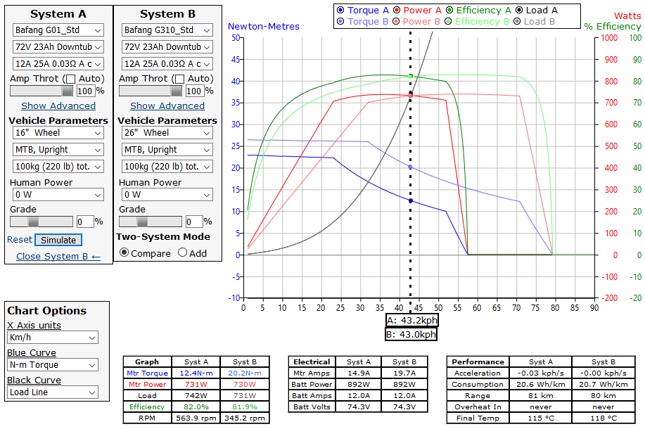
At high speeds (50+ kph) it's actually pretty realistic to continuously do ~1200 watts of input power, ~1000 watts of output power, with the motor in the 20-22 Nm torque range. 1200 watts at lower speeds like 25-30 kph requires a motor torque that is quite near the mechanical limits of the plastic gears.

If you don't mind, where exactly did you place the core sensor for these tests?

Glued to the windings right here.

G310ThermistorLocation.jpg

You can also see how easy it is in general to pass through some extra sensor wires beside the main motor cable once you disassembly the motor remove the wire side axle stub. Then it's just a straight line diagonal hole and you can use a jewelers scredriver or similar to make space beside the phase cable to tuck the temperature signal wires beside it.

Did you notice any increase in drag?

The normal method that I use to measure the drag with Statorade testing in a direct drive motor is by measuring the no load current draw of the hub motor. That doesn't work as directly in a geared motor since it includes all the core losses which wouldn't be present when you are just pedaling the hub with no power. In this particular case, the no load power consumption decreased rather than increased with the addition of ATF. For instance at 350 rpm with no fluid, the unloaded current was 1.18 amps. After adding 50mL of transmission fluid, it dropped to 1.03 amps.

I can only conclude that the oil in the motor has washed out and dissolved much of the bearing grease and gear grease, lubricated the shaft seals, and that this more than offset the additional viscous drag caused from the oil sloshing around.

How did you fill the motor,

I did my usual trick of drilling one of the disk bolt holes all the way through and then used a syringe to inject it after the motor had been reassembled, and closed that hole with a small M5 bolt while the tests were underway.

View attachment 3

View attachment 1

If I was doing this on a bike and not needing to incrementally add small amounts of fluid for the sake of knowledge and science, I'd just open up the side plate, pour in the fluid, then screw the side plate back in place. The motors open up this way quite easily, and you don't have to worry about resealing the side cover since there is an o-ring around the perimeter of the side plate that seals it for you.

G310ORing.jpg

and did you experience any leakage through any of the seals? Did you clean out the gear grease beforehand or did the oil wash it out on its own?

Surprisingly and pleasantly there has been zero leakage at all yet, with about 35 hours of cumulative running so far. But the motor is just upright and not bouncing around like it would on an actual ebike, If you tilted it on it's side I'm sure it would leak right through the cable exit since I made no special effort to seal that after passing through the themistor wire.

Still, the fact that there's been any leakage visible on the wind tunnel is really promising that the stock shaft seals and O rings on the G310 motor are gonna be up to the task.

Since you seem to be using ATF, I'd also be interesting to see if it attacks any seals, cable insulation/enamel or the gears.

I'm really interested in this too. The only reason that I'm using the transmission fluid for this thermal characterization is because I had some on hand from previous motor experiments not because its necessarily the best suited for long term rubber/chemical compatibility. For that it's been suggested that a lightweight pure synthetic gear oil would be more appropriate than whatever concoction of chemicals goes into ATF.

So don't consider these results as some endorsement of ATF in particular. I think all cooling fluids would perform almost exactly the same thermally. Then there's a separate task to see of all the liquids out there which ones can be safely poured into a hub motor with the least adverse affects on the gears, ball bearings, wire insulation, rubber seals etc.

That's not something I plan to do but am hoping that armed with this test info, others will be encouraged to try things out and report back if they notice any compatibility issues in the long term.
 
grindz145 said:
You seriously never cease to amaze me with your unyielding dedication to the craft Justin! 50% increase is significant!

Thanks Grindz, I almost forgot to post the updated results! I've now run the experiment at up to 50mL, but the 50mL test had a problem in that with the additional thermal conductivity I couldn't get the motor core to reach the 80oC target with field weakening. The motor controller got unstable putting more than 27 amps of field weakening current into the hub at low RPM's which was required to raise the temperature that much. So the 50mL test data was done at a lower core temperature (between 68-75 degrees) and isn't perfectly comparable. I'm going to try and repeat this later after tweaking some controller settings and then keep adding fluid until the performance plateaus.

Up to now though, it seems like we're still not there yet. When the steady state data is analyzed and converted into conductivity values the results show that there is still an improvement with small fluid amounts, but that the bigger improvements start to happen around 30 mL. Here is the thermal conductivity plotted against the mL of ATF fluid, with each line representing a different motor RPM / wind speed:

G310ThermalCondVsATF.jpg

And here is that same data plotted against motor RPM, with each line now representing a different Statorade fill quantity. The biggest jump in the gap between lines happens as expected between 26 and 32mL, but there seems to be continuous improvement with high fill levels beyond this:

 
Thank you for the detailed answer! Your dedication to research and providing information is, as always, magnificent.
 
So how do these stack up vs running the slowest wind Bafang SWXH's (201rpm / 5.6rpm/V) at high voltages? Seems to be about the same torque (in the std wind) but higher voltage limited speed limit.

Playing with the simulator, using the G01 standard wind (which I'm pretty sure is the motor sold as the SWXH), and using it in a 16" wheel to scale the 10rpm/V of the standard to the same no-load ''speed' of the 5.6pmg/V slow wind yields the following (when paired with a 750watt controller limit and very low 25amp phase amps):
VVimwhd.png

The motor torque is incorrect due to it being a different wind speed, but everything else seems to match up with real life. In essence though the SWXH seems "better" in that it's efficiency range is better spread throughout the actual usable range and peak power is reached sooner.

A0ZgfCZ.png

Adjusting wheel sizes to scale the motors to the same no load speeds the G310 has higher torque throughout (as you would expect with the increased reduction ratio), and a very slight efficiency drop through the range (more gear loss?) but slightly higher peak efficiency 83.4 vs 83.8 (thinner laminations and better copper fill?)

rfJFkt1.png

What I found interesting in this image is despite the same motor power and the G01 being at a higher efficiency the G310 actually lasts longer before overheating? So the G310 has better heat shedding ability, or am I missing something?

So am I missing something in the larger picture? The G310 seems essentially the same in the real world vs the G01, as long as you aren't speed limited by low voltages. Anything 70 volts and up you would be better with the older SWXH.

Is scaling the G01/SWXH wind speed using the wheel size even applicable, or do I need to model a custom motor to accurately simulate the slowest wind SWXH as its not modeled?
 
You're running it on a scenario which it falls short in. The G310 never spins up fast enough to hit it's stride.
The G310 is capable of much higher continuous power and better efficiency at higher RPM.

Take the dual motor comparison out of the equation and try 48 or 52 volts and 20A in a 26" wheel separately.

The G310 is the most power dense hub on the market. It's 5.6lbs and you can see around 700w continuous out of it for an hour and a half, which is what i'd call 'continuous' as many batteries do not go that far. ( put 100w of pedal power in and you've extended that time to beyond 2 hours )
Let's compare this to the leafmotor 1500w ( direct drive ) which is my current benchmark for hub motor power density..
Leafmotor realistically does just about 1900W continuous because it's underrated.. but it's 16 lbs..

16lb / 5.6lb = 2.8571.
2.8571 x 700w = 2000w.

2018-11-15 08_17_20-Motor Simulator - Tools.png
 
wil said:
Adjusting wheel sizes to scale the motors to the same no load speeds

Ah no, you can't do that for a fair comparison because you are then comparing the motors at different rpms and torques. The smaller wheel size almost always has the advantage since it needs to produce less torque for the same thrust. It's like doing this
https://www.ebikes.ca/tools/simulator.html?bopen=true&axis=kph&motor_b=M3548&motor=M3525&batt=B4823_AC&batt_b=B4823_AC&cont=C25&cont_b=C25&wheel_b=14.3i
And concluding that the fast wind H3548 motor is way more powerful and efficient than the H3525.

Is scaling the G01/SWXH wind speed using the wheel size even applicable, or do I need to model a custom motor to accurately simulate the slowest wind SWXH as its not modeled?

Even easier we made a simple KV adjustment slider for doing this which will take the existing motor parameters and automatically scale the effective motor resistance and inductance as if it had been produced with a different winding speed. Just use the KV slider in the advanced dropdown section on one of the motors so that they hit the same unloaded RPM. It's explained in the first post of this thread (which you should also read in its entirety):
https://endless-sphere.com/forums/viewtopic.php?t=89877#p1309975

The Bafang G01 motor is a larger and heavier hub than the G311 (3.0kg vs 2.3kg), in a more conventional geometry (outrunner motor with a ~4.4:1 gear reduction, vs Inrunner with an 11:1 reduction). I would have generally expected the G01 to be more powerful and robust, and to generally have a better peak efficiency (straight cut spur gears at a lower overall ratio should be more efficient than a helical gear at a higher reduction ratio), but surprisingly this isn't what we see. Here is the actual comparison that you want to do (set the G01 KV to 0.85 of it's actual value)
https://www.ebikes.ca/tools/simulator.html?bopen=true&motor=MG310_STD&motor_b=MG01_STD&k_b=0.85&cont_b=cust_20_40_0.01_V&cont=cust_20_40_0.01_V

The performance difference is slight, but across the board the G310 fairs a bit better, in spite of being almost 25% less weight.

So am I missing something in the larger picture? The G310 seems essentially the same in the real world vs the G01, as long as you aren't speed limited by low voltages. Anything 70 volts and up you would be better with the older SWXH.

I would say that the heavier G01 motor would be better for both really high RPM's and for handling higher power levels before the gears fail. We've seen lots of firsthand incidents of people stripping the gears on a G310/311 when running with controllers that will put >50Nm of torque on the wheel. And the inrunner magnets on the G310/311's can separate from the rotor at really high speeds too, as I explained in this thread:
https://endless-sphere.com/forums/viewtopic.php?f=3&t=95478#p1423266

If you are using the motor with a controller that will phase current limit or power limit things such that the motor torque is less than 40 Nm, and you are running the motor at generally less than 450 rpm (equivalent to 35mph in a 26" rim) then the G31X certainly has the advantage. Slightly better performance, way less noise, and a pound and a half less weight.
 
justin_le said:
The performance difference is slight, but across the board the G310 fairs a bit better, in spite of being almost 25% less weight.

So actually using the simulator correct (thanks Justin, the new features since I used this 4 years ago are amazing!) I am considerably more impressed with the G310 now!

https://www.ebikes.ca/tools/simulator.html?bopen=true&motor=MG310_STD&motor_b=MG01_STD&k_b=0.85&cont_b=cust_20_25_0.01_A&cont=cust_20_25_0.01_A&hp=0&hp_b=0&batt=cust_60_0.1_5&batt_b=cust_60_0.1_5&black=load
YSeYwBD.png

Chasing speed the G310 absolutely outclasses the old SWXH, ~1000 watts and the G310 isn't a molten 200 degree blob. The G310 appears to be in another league vs the SWXH at literally all applications. I'm not comfortable pushing more than 30nm/800 watt (at 20s) out of my SWXH anyway, even with an oil fill, so the G310 really is just better™.

Now the only thing on my wishlist is for Bafang to make a slow wind version for people prepared to run high voltages. It would mean less wasted top end, and the efficiency range moved down a bit from covering so far past max speed ranges. 7.2 rpm/V would be great for 72v-100v battery ranges in 26" wheels, maybe a ~6rpm/v for larger wheels. This would also avoid them being run in smaller wheels at high rpm where the magnets fling off.
Only issue would be gears being stripped, a phase amp limiting controller would be a must!
Maybe it's time to build a new bike...
 
*shrug* you can make about as much power with low volts and high amps.

I did 45mph on a super fast winding DD on 47v, no problem. Had to tune the amps down from 85A because i couldn't keep the front wheel on the ground. That's how the leafmotor thread got started.

I still have the top speed record on an 8T MAC motor. ( which is sad because that crown would be easy to take )

And here's my old crystalyte 3548 burning rubber.. the fastest winding of them all..

[youtube]T1beC8eALYA[/youtube]

I've ran a couple ultra slow winds and while the amps go far to make torque, i found they're nothing really special

A fast winding is good with the right controller ( 3077's instead of 4110's etc ) and a thick enough power bus so that you aren't making heat with amps.
 
justin_le said:
1N4001 said:
Since you seem to be using ATF, I'd also be interesting to see if it attacks any seals, cable insulation/enamel or the gears.

I'm really interested in this too. The only reason that I'm using the transmission fluid for this thermal characterization is because I had some on hand from previous motor experiments not because its necessarily the best suited for long term rubber/chemical compatibility. For that it's been suggested that a lightweight pure synthetic gear oil would be more appropriate than whatever concoction of chemicals goes into ATF.

So don't consider these results as some endorsement of ATF in particular. I think all cooling fluids would perform almost exactly the same thermally. Then there's a separate task to see of all the liquids out there which ones can be safely poured into a hub motor with the least adverse affects on the gears, ball bearings, wire insulation, rubber seals etc.

That's not something I plan to do but am hoping that armed with this test info, others will be encouraged to try things out and report back if they notice any compatibility issues in the long term.

I found someone with experience running ATF in their geared hub. It ended up damaging cable insulation and loosened the magnet glue: https://www.pedelecforum.de/forum/index.php?threads/zusatzk%C3%BChlung-f%C3%BCr-nabenmotoren.20750/page-10#post-788399

And according to this person, fork oil also damaged insulation: https://www.pedelecforum.de/forum/index.php?threads/zusatzk%C3%BChlung-f%C3%BCr-nabenmotoren.20750/page-8#post-496354

So both ATF and mineral oil based fluids are not a good idea.

Silicone oil should be more suitable. It's chemically inert, an electrical insulator, transfers heat well, naturally prevents foaming and is available in very thin viscosities.

(Teflon-based oils could also be worth looking into.)
 
I myself have not played around with the ratio's from my previous understanding I always ASSumed a 2:1 ratio or phase amps is double the battery amps is a good place to start, but not really going over 2.75. You know how ASSumptions go :oops: but instincts and a shit ton of reading, is helpful so atleast I was on the money.


Very helpful!

neptronix said:
You can think of phase amps and battery amps as a ratio that adjusts the torque curve of the motor.
Here is what you can expect from tuning based on that ratio.

1:1 ratio: The motor has almost no initial torque at all and shutters and stalls because of this. Like a 1990's Honda Civic with 500,000 miles on the motor and an exhaust and intake that's 2 times larger than it should be.. even the mid range torque suffers..
2:1 ratio: This is more like a typical internal combustion engine where the torque from a stall is weak, and by the mid to high range is pretty strong.. this is ideal if you're trying to force yourself to pedal from a start.
2.25:1 ratio: This is a flat torque curve on most motors.
2.5:1 ratio: This is where the motor starts having more low end torque than mid and high.
3:1 ratio and beyond: Wheelie time!

Most absolutely stay away from 'wheelie time' on a geared motor.
Torque is the biggest challenge for your nylon gears and the most torque can occur in the lower section of the power band.

Start at 2.25:1 ( IE 18A batt, 40.5A phase ) and adjust for taste.
 
Back
Top