Do I need diodes with this layout?

MJSfoto1956

10 kW
Joined
Jul 28, 2010
Messages
960
Location
Boston, MA
So I'm getting closer to to finalizing the details of the upgrade of my 72V/2000W Chinese eMoped/eScooter.

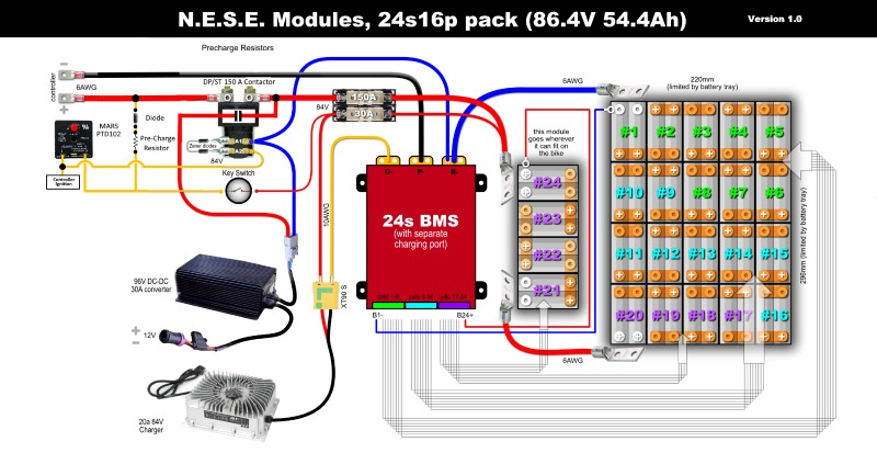
The ultimate goal is to replace the 2000W QS 205 motor @ 72V with an 8000W QS 273 motor @ 84V. However, my first step will be to upgrade the controller, followed by the battery system, and lastly the motor. Currently I'm looking at building a 24s16p Li-ion pack made from 48 NESE 8p modules controlled by a 24s BMS. This gives me an 86.4V 54.4Ah system with a max charge of 98.6V.

While I don't "think" this particular electrical layout needs any diodes or resistors, I am putting it out there for the experts to weigh in. Any advice appreciated.

45945695381_b814c75753_o_d.jpg
 
Nice looking chart. I don't see any need for a diode or resistor. Why were you thinking you needed them?
Edit: Actually you might want a diode after the 30 amp fuse before the battery as insurance.

:D :bolt:
 
e-beach said:
Edit: Actually you might want a diode after the 30 amp fuse before the battery as insurance.

What kind of diode? Schottky? Zener?

And wouldn’t that prevent the charger from doing its job? Or is the idea to protect the charger from the battery?

M
 
It would be to protect the charger. Use the kind that is used in a bridge rectifier.

:D :bolt:
 
Depends on the charger.

Smart chargers like the Satiator need "access" to the battery voltage to tell what it actually is at under charge current and at rest. These also usually disconnect themselves from the battery when charge is complete, so if it's left connected all the time, it doesn't drain the battery.

Dumb chargers like Meanwell LED PSUs and most of the cheap cahrgers included with batteries don't do any checking/etc., and a diode can help prevent them from draining the battery when not charging, if the charger is left connected all the time (like on my SB Cruiser trike, where it's built into the trike).

If you think someone might stick a piece of metal in your charger port and short out the battery, a diode is a good idea, but I expect that's a rare event.

The only other reason for a diode is to prevent reverse connections, but if you have a polarized connector, and you test the wiring before hooking things up, you don't have to worry about it.
 
I've never seen a contactor with a 100 volt rated coil...
 
Perhaps not what you where looking for. But the first thing that came to mind was a pre-charge resistor for the controller, and a freewheel diode for the contactor coil...
 
jonescg said:
I've never seen a contactor with a 100 volt rated coil...

It would be possible to use a contactor with a 12v coil and run it off the DC-DC converter.

It might be good to put a diode across the contactor coil (reverse biased) if it doesn't have one built-in. The diode catches the voltage spike when you turn the coil off.

The controller Vcc doesn't need much current, nor does a 84v relay coil, so the 30A fuse should probably be much smaller, like 3A.
 
fechter said:
The controller Vcc doesn't need much current, nor does a 84v relay coil, so the 30A fuse should probably be much smaller, like 3A.

Yeah perhaps I should add a third power circuit (3A) -- the 30A is primarily for the charger circuit. I was just "piggybacking" the contactor's coil off of that.

M
 
TommyCat said:
...the first thing that came to mind was a pre-charge resistor for the controller, and a freewheel diode for the contactor coil...

Thanks! This page seems to describe my needs perfectly: http://zeva.com.au/Tech/ContactorJewelry/
 
One thing though -- with the pre-charge resistors in place as shown in the updated diagram, won't that send a small amount of power to the DC-DC converter? Seems wasteful. I'm thinking the pre-charge resistors should be on a momentary switch which I would engage just prior to turning the key (not unlike a diesel motor). Thoughts?

M
 
Until the day you forget to use it. A switch for the dc to dc converter?

:D :bolt:
 
MJSfoto1956 said:
One thing though -- with the pre-charge resistors in place as shown in the updated diagram, won't that send a small amount of power to the DC-DC converter? Seems wasteful. I'm thinking the pre-charge resistors should be on a momentary switch which I would engage just prior to turning the key (not unlike a diesel motor). Thoughts?

M
Yes, the current from the precharge resistor going to the DC-DC would be a problem.

One solution would be to have a separate smaller contactor for the DC-DC converter with no resistor across it.

Another solution would be to find a 3 position switch that goes off-precharge-on, so you are forced to have the right sequence.
 
A number of keyswitches have an Off, Accessory, and On (or Ignition) set of positions. The Accessory position could be used for precharge, and On for turning on the contactor.

Some of them keep the Accessory position on while Ignition is on, most of them don't.

One of the ones I had a long time ago had a springloaded Ignition position, like a car's, that returned to the Run position--those aren't suitable for your purpose, unless they *also* have an Accessory position before the Run, to use for precharge.
 
Based on reviewing many previous threads here on ES on this very subject, I have come to the conclusion that the minor amount of current used to maintain the caps in the controller is not worth the bother and all the complexity needed to achieve it. Instead I am now planning on simply adding a circuit breaker before the controller and leave it on all the time -- except when I put the bike to bed in the winter. Additionally, there will be a precharge circuit added after the key switch. Upon the arrival of spring one needs to simply turn the key on for a minute or so to fill the caps, then flip the circuit breaker on for the rest of the season. The result is a much simpler, much less costly solution. As always, comments welcomed.

45927821312_a1234eee43_b_d.jpg


M

24s16p, 84V 54Ah NESE modules + BMS wiring diagram
 
Simple is good.

I've seen many setups that just use a big solar circuit breaker and no precharge resistor. The big breakers can apparently handle the inrush current without being damaged. Precharging won't hurt, but nice if the breaker can handle it if you forget.
 
MJSfoto1956 said:
Pretty close to final layout...


If you don't mind me saying, I'd double check the converter's circuit breaker size. (Seems way too big.) And the use of a Zener diode in the pre-charge circuit?
 
BOM (Bill of Materials) for my proposed 20s20p system:

(80) N.E.S.E. 5p Modules
(80) N.E.S.E. Serial bus bars
(80) N.E.S.E. double caps
(400) 18650 3400mAh Li-ion batteries
(1) VLDL DANL 72V max 20A charger
(1) Daly 20s BMS
(1) 72Vdc/12Vdc Waterproof 25A converter
(1) PowerVelocity 20kW controller + Bluetooth app
(4) 6AWG 2-hole lugs
(3) 6AWG 1-hole lugs
(3) 6AWG non-insulated flag terminals
(3) 8AWG 1-hole lugs
(4) 10AWG 1-hole lugs
(4) 6AWG Silicone Wire
(1) XT90 spark resistant adapter
(1) C-13 panel mount 110V adapter
(1) US 110V --> C-13 extension cord
(1) J1772 --> C-13 adapter cable
(1) 75A circuit breaker
(1) 25A circuit breaker
(1) 20A circuit breaker
(2) recharge resistors
(1) zener diode
 
Back
Top