bluetooth BMS?

EbikeAus said:
Just reporting that the app seems to connect perfectly fine with my new Samsung s9, seems to connect quicker than my old s5 :D

THat's expected...faster phone.
 
Here is an app to monitor/control multiple BMS devices in one battery pack:
https://mono.software/2018/11/15/multiple-bms-monitor/
 
mario1122 said:
Here is an app to monitor/control multiple BMS devices in one battery pack:
https://mono.software/2018/11/15/multiple-bms-monitor/

Thanks for making this :thumb:
I'm sure I will need this someday.

A few different dashboard layouts would be cool, like raw values for battery current instead of an x10 multiplier.
 
mario1122 said:
Here is an app to monitor/control multiple BMS devices in one battery pack:
https://mono.software/2018/11/15/multiple-bms-monitor/
I finally got around to reading your thread on this app. Any chance you would be willing to make an APK? I do software development so I understood what you are doing here. BUT, lots of folks are not so inclined or are tech incapable. An APK would make using your app much easier for everyone.
 
Hi i have the xiaoxing bms. Why does the bms sometimes pulse on cell overvoltage rappidly ? When near end of charge ? I.e it doesnt just stop at the end it pulses...

Also how to fix this? Is it a setting in bms or is the voltage in the charger too high ?

Does it stop chargeing only when one cell is high ? Or does it also stop if pack voltage is correct ?

Also for the open balance option. What does this open or close option mean ?

Is their any downside to always useing a static balance ? This is an old pack and charge balance is not good enough to keep it balance.

Does anyone get resistance readings as i dont ?
 
I have experienced the Pulse thing.

It happens when you set overvolt cut-off to 4.2V and overvolt recovery to 4.18V or something like that.
So while charging your cell(s) reaches 4.2V and the BMS cuts off the charger, then the Cell voltage drops down to something like 4.17V and the BMS enables the charge again and that's how you get the pulsing effect.

The solution: Change the overvolt recovery voltage to some lower value like 4.15V or 4.1V
 
Btw. I wrote some open source firmware for the LLT bluetooth BMS to use it in a Xiaomi M365 scooter (scooter requires battery with proprietary communication protocol): https://github.com/BotoX/xiaomi-m365-compatible-bms
Might be of interest for some people here.
 
I recently bought one Bluetooth BMS from taobao.com. But the seller is not that helpful and so I need to get help from here.

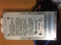
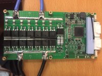
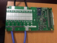
Below are some photos of it.
IMG_1375a.jpg
IMG_1377a.jpg
IMG_1379a.jpg

This bms will be put inside a battery case which has very limited space for bms. Even thought I plan to give up the space of 9 x 18650 cells for it, I still need to cut away a small piece (about 2 x 4mm) of the PCB on two sides as marked in red on the below photo 4. I guess it is okay to do because there is no components and/or circuits nearby. But I am not an expert, therefore, I contacted the seller and ask them if it is okay to do so. The seller only said no and refused to tell me the reason why. Now, I would like somebody from this forum to comment on whether it is okay to do so. If no, please explain the reason so that I can learn something.


Also, I only got the Chinese instructions and Bluetooth app from the seller. I can understand Chinese but the English ones will be much better for me. If any body has the English version of installation instructions and Bluetooth app, please send me a copy.

Originally, I plan to ask the factory directly on the above questions. But I could not find the website and contact information of the factory from the internet. This bms should be from the same factory as the one with photos posted by ElectricGod on Sep 11, 2018 (https://endless-sphere.com/forums/viewtopic.php?f=14&t=88676&hilit=bluetooth+bms&start=700). If anybody knows about the factory contact and website, please advise.
 
The top and bottom side of the PCB copper are connected to each other. You can see this, because there are small holes with copper inside. You can check that with a DMM. And if this is the case there should be NO PROBLEM to cut out these small rectangles. You will remove a bit of the copper but this should be no problem at all. Especially as you connected two wires on each side balancing the load.
 
izeman said:
The top and bottom side of the PCB copper are connected to each other. You can see this, because there are small holes with copper inside. You can check that with a DMM. And if this is the case there should be NO PROBLEM to cut out these small rectangles. You will remove a bit of the copper but this should be no problem at all. Especially as you connected two wires on each side balancing the load.
Hi izeman, thanks for your comment. I have checked that accordingly, and you are correct that the top and bottom side of the PCB copper are connected to each other.
 
I don't see any issues with cutting into that area with all the through holes in it that connect the traces on both sides of the board together. There is a slim chance that some tiny trace is inside a third layer of the board, but I seriously doubt it. There's far better ways to run something like that without having to pass between all those interconnect holes. I'd be willing to cut into those areas without worrying about causing issues.

I do have 2 things that I'd do in the process.
1. The power traces on a 100 amp board ought to have lots of copper on them. All I see here is the traces and solder on them. They really need copper added to them. That means copper at C-, P-, B- and right before the shunts. 14 awg copper wire commonly found in household wiring will do the trick. If you don't want to buy some Romex, I bet there is a construction site near by you that has scraps laying about that you could scavenge from.

2. Since you are undermining that interconnect section a fair bit by removing large portions of it, Use some more 14 awg wire to wrap around one side of the board to the other.

Note: Copper wire is round. However, copper is very ductile. That means it can be smashed and bent easily without compromising its integrity. Strip off the insulation from a length of wire and use a hammer to flatten the wire out. No harm done and this will lower it's profile on the board.
 
I snagged your pics and blew them up a good bit to get a closer look. Sorry for the grainy pics.

Board top:


board%20top%20-%20close-up.png


Board bottom:

board%20bottom%20-%20close-up.png


Notice the red boxes. They are P- and this board has no direct way to let you solder a connection here. For power output to your EV, you want to use P- and NOT C-. P- is Power output and C- is Charge input....dumb to NOT have this! However, you can add P- to this BMS. 14 awg wire is handy stuff. Solder 2 strands of it on top of the mosfet tabs once you replace all the B- chinesium mosfets. If those 14 awg copper stands extend to the edge of the board, now you can solder onto them for P- access.

Notice the orange boxes on the board top. There are identical places on the bottom of the board too that I did not mark since the bottom is unpopulated. These areas are inadequate as is. They really need copper reinforcing...even for 100 amps.

Notice the blue box. It says "ANTBMS-16S". That gives you a clue to the manufacturer. The 24S and 32S smart BMS mentioned in this thread are also commonly referred to as "ANT BMS", but they use different components. I'm not sure, but it's possible the same app that works for the 24 and 32S versions will also work for this BMS. Worse case, google for ANTBMS-16S and see what you find.

This BMS is not like the other smart BMS's talked about here. It may come from the same factory, but I don't think so. See that single large IC on the board top? That's the charge controller. The smaller IC is possibly an atmel 328. It is unlikely that the same software we use for the smaller smart BMS discussed here will also work with this BMS. It's probable that the app for the larger ANT BMS's talked about here also won't work for your BMS.

This BMS has loads of potential for insane current handling. One whole side of the BMS is unpopulated. I bet that set of mosfets on there are garbage. Or if they are some well known mosfet, they are Chinesium versions. AKA, pull off all the mosfets on B- and replace with at least legit IRF4110's and then add a load more to the other side of the board on B-. You will be adding a bunch more .005 ohms shunts too. I bet with all of them being legit 4110's that this BMS could do 300 amps all day long. If you use larger shunts and better than IRF4110's...maybe 400 amps.

Of course if that 100A spec is already overkill for you, then don't bother. If it was my BMS, I'd be modding it. =)

Can you post the URL where you found this BMS please?
 
One more post on this BMS...

Small components, board top:
The large IC in the orange box is the charge controller. I don't know what part it is. The red box looks like 2 DC-DC converters. Probably one supplies 5 volts and the other 12 volts. Under the grey thermal gap filler in the green box is a bunch of SMT resistors. I can't see them so I have no idea of their size or wattage. I bet they are .25 watt resistors or less. That would imply this BMS can do a max of about 1 amp balance current. What are those 2 connectors in the blue boxes. I have some 7S smart BMS's that have input and output connectors on them so that multiple BMS's can be daisy chained together. This allows you to have up to 22 of them in series or 154S. These connectors may serve the same purpose or they may support external balance boards so that this one BMS can control far more than 16 cells. The left connector has 3 pins and the right one 5. I see a single opto-isolator on the board and space for 3 more. Maybe the 5 pin connector is for an LCD in which case a single opto-isolator is all that's needed. If the 5 pin connector was used for connecting to another BMS, then TX and RX would be needed and that means at least 2 opto-isolators.

board%20top%20small%20components.png


Small components, board bottom:
The green box is a BT06 bluetooth module. This exact module is used on the 24S and 32S ANT BMS's, but is NOT used on the smaller smart BMS presented in this thread. The red box is an STM32 CPU. In my last post I thought it might be an atmel 328...that's incorrect. The STM32 is also used on the 24S and 32S ANT BMS's. The orange box is the active balance components. Those transistors are pretty small. No bigger than the ones used on the smaller smart BMS's. I suspect this BMS really balances at no more than 50mA...like they do.

Board%20bottom%20small%20components.png
 
Hi ElectriGod, thanks for your comments.
Sorry, I am now in Asia. I will head for the airport for a 6-day trip in Malaysia in about an hour. Therefore, I only have time to post a short reply. But definitely will post more after the trip.

"Can you post the URL where you found this BMS"

I found it at https://item.taobao.com/item.htm?spm=a1z09.2.0.0.57ad2e8do6M27G&id=570909559482&_u=41nfs4840103. But I don't suggest people buying from them because of the poor customer service and not professional enough as I mentioned in my first post.

There is another taobao seller selling the same bms but the price is higher, and the link is https://item.taobao.com/item.htm?spm=a1z0d.6639537.1997196601.100.424374841HYUOX&id=570867089295. And I think sooner or later, there should be sellers selling them in Ebay or Aliexpress.
 
tmho said:
If anybody knows about the factory contact and website, please advise.

I found your BMS on ebay.
https://www.ebay.com/itm/320A-7S-16S-8S-10S-13S-Li-ion-LiFePO4-Battery-PCB-BMS-Protection-Board-Bluetooth/264061811334?_trkparms=aid%3D777003%26algo%3DDISCL.MBE%26ao%3D1%26asc%3D20140131123815%26meid%3D0ca7ef6f88c44b66a471c779f98ea1ab%26pid%3D100169%26rk%3D2%26rkt%3D11%26sd%3D192713045620%26itm%3D264061811334&_trksid=p5411.c100169.m2942
 
tmho said:
Hi ElectriGod, thanks for your comments.
Sorry, I am now in Asia. I will head for the airport for a 6-day trip in Malaysia in about an hour. Therefore, I only have time to post a short reply. But definitely will post more after the trip.

"Can you post the URL where you found this BMS"

I found it at https://item.taobao.com/item.htm?spm=a1z09.2.0.0.57ad2e8do6M27G&id=570909559482&_u=41nfs4840103. But I don't suggest people buying from them because of the poor customer service and not professional enough as I mentioned in my first post.

There is another taobao seller selling the same bms but the price is higher, and the link is https://item.taobao.com/item.htm?spm=a1z0d.6639537.1997196601.100.424374841HYUOX&id=570867089295. And I think sooner or later, there should be sellers selling them in Ebay or Aliexpress.

I'm familiar with taobao. If you are in Asia, they will sell to you, but the rest of the world...not so much.
 
You can use some service like Taobao Focus to receive it for you and then they'll ship it to you.
 
Hi everyone,

ICGOGOGO has put their product line on ebay. The cost is a little higher thanks to ebay fees, but for folks skittish about buying on aliexpress, now you have paypal and ebay backing up your purchase.

https://www.ebay.com/usr/icgogogo?_trksid=p2047675.l2559

Just a few of my favorite things...

https://www.ebay.com/itm/8S-24S-Lifepo4-li-ion-Lipo-Battery-Protection-Board-Smart-BMS-Balance-Bluetooth/192713045620?hash=item2cde97b674:m:mmYGtW2LCsV0HOzua9mBVkw:rk:1:pf:0

https://www.ebay.com/itm/16S-32S-Lifepo4-li-ion-Lipo-Battery-Protection-Board-Smart-BMS-Balance-Bluetooth/192687500566?hash=item2cdd11ed16:m:m2yXZmRnmU5gzzMfSmlE6fA:rk:5:pf:0

https://www.ebay.com/itm/30S-Lipo-LiFePO4-Lithium-Battery-Protection-Board-Li-ion-Smart-BMS-APP-Bluetooth/192748199225?hash=item2ce0b01d39:m:m4NiUIzgdL6GQLVYYxFH-Xw:rk:8:pf:0

https://www.ebay.com/itm/20S-Lipo-LiFePO4-Lithium-Battery-Protection-Board-Li-ion-Smart-BMS-APP-Bluetooth/192748176334?hash=item2ce0afc3ce:m:mBt0HaOqUqiZBbTtOkF05zw:rk:9:pf:0
 
Nice.
I can already see that this BMS is the most popular:https://www.ebay.com/itm/8S-24S-Lifepo4-li-ion-Lipo-Battery-Protection-Board-Smart-BMS-Balance-Bluetooth/192713045620?hash=item2cde97b674:m:mmYGtW2LCsV0HOzua9mBVkw:rk:1:pf:0

But for the JBD BMSs, I would buy them from lithiumbatterypcb.com since they have the latest PCB and firmware version.
They also accept PayPal and ship free or express for like 15$.
 
ElectricGod said:
Of course if that 100A spec is already overkill for you, then don't bother. If it was my BMS, I'd be modding it. =)
I am back to Hong Kong from Malaysia.

I am going to use it for my new 48V battery pack project whick will be for my ebike. The ebike needs 20A maximum, most of the time just under 15A. Therefore, I am not planning to modify it now.
 
Back
Top