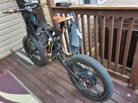
Noob EEB Enduro Build

I went with a 19” and the stance is perfect for me as a 5’10” rider with the rear shock bracket flipped upsidedown in the lowest mount position. I sit just flat footed which feels perfect.

I live in flat as a pancake Texas so went with a 5T. I havent tried any hill climbs and am honestly a little concerned to put a heavy load on my Sabvaton controller after shortcircuit911’s experience.

If you are considering a Sabvaton you might consider his build thread.

Good luck on your build if you decide to pull the trigger be sure to post a build thread!
 
Monterrey (for reference a good 6hr south drive from Austin), my home town, does have steep roads going up the mountain, should I go with a 6T??

I will pull the trigger and I will post a build thread.

Thanks for your input.
 
Sorry mine is a 4T and I think you are on the right track being more windings = more torque.

Hopefully some of the smart folks will chime in but I found this:

http://52.25.253.50/forums/viewtopic.php?t=93839
 
Gstegman said:
Great news on your build. I have about 25 miles of test rides on the bike.

For now the controller is horizontally mounted between seat and handlebars with zipties. I used a piece if foam from EM3EVs outstanding packaging. The battery is at the lowest part of the frame again with foam.

I threw the tires on a bathroom scale one at a time and suspect I am at around 125lbs, ouch!

No rear brakes yet as I havent solved the issue of my phase wires hitting the rear rotor. I have a plan but need to get my little CNC mill going again (moved across country a few months ago).

As others have mentioned the moto seat is less than comfy on my old arse so I may source some foam options from the pitbike crowd.

I can tell you its night and day from my 2018 RadRover. I am having a blast!

Best of luck with yours, keep us updated...

Hi Gstegman. Good to hear your up and running. Any joy with the rear rotor and phase wires yet? I've had the same problem with mine, I 'think' I've solved it by counter sinking the rotor and replacing the stainless button head bolts with stainless counter sunk Allen bolts. Ive got the maxus 5k and that's an even bigger lump than the 3k! I had to space my rotor off the motor to because the caliper was touching the motor! So had even less room for phase wires. :roll: I also hand filled a small curved slot in the frame dropout just to give a little more room for the wires.
 
I have not entirely solved the phase wire issue. I did counter sync but the rotor was still rubbing a wee on the white protective covering. I wanted to ride it so much I have been rolling around with front brake only.

Do you have a build thread?
 
Gstegman said:
I have not entirely solved the phase wire issue. I did counter sync but the rotor was still rubbing a wee on the white protective covering. I wanted to ride it so much I have been rolling around with front brake only.

Do you have a build thread?

Yeah it seems to be a major issue with these builds,the wires and the dropouts. I can't understand why the frame manufacturers and or the motor manufacturers aren't trying to solve this problem? It seems to me that the axle just needs a bit more length in it and meat around where the wires come out? Like the flats on the axle coming out further near where the hole is for the wires..if that makes sense. It's pretty easy to fudge the swinging arm out half an inch or more if need be. No haven't got one yet but will do when I start putting it back together,the spacers I had machined up for the sloppy rear shock mounts came today so I can start rebuilding it and I will post pictures then. Want to get it back together as a complete rolling frame before I start the electrics and wiring bit,as in the brakes,crank,chain etc all sorted out. Hope you get your rear brake issue sorted soon.
 
Can anyone please explain how to properly install a 5KW QS (205) on an EEB frame? It comes with two bolts and a rectangular piece on each side of the axle, but with both the rectangular pieces and the freewheel, it won’t fit. I don’t have a disk on yet either, I’m going to go get one today.

I can make it fit without the rectangular pieces but I don’t know if they’re needed. Also I’m concerned about the wires pushing up against the side.

Thanks!
 
rzrsharp519 said:
Can anyone please explain how to properly install a 5KW QS (205) on an EEB frame? It comes with two bolts and a rectangular piece on each side of the axle, but with both the rectangular pieces and the freewheel, it won’t fit. I don’t have a disk on yet either, I’m going to go get one today.

I can make it fit without the rectangular pieces but I don’t know if they’re needed. Also I’m concerned about the wires pushing up against the side.

Thanks!

I have it without the rectangular pieces. I don't think that thouse are needed because the frame has strong enough dropouts. I run mine also without rear diskbrake using only variable regen with hydraulic hand lever and pressuresensor. I have seen that some people run phase wires towards back of the swingarm to get better clearance but that looks little weird to me. But do whatever works to get that motor mounted securely and not destroying the phasewires..
 
Gstegman said:
If we are talking about the same thing, mine are on the outside of the swingarm.090E0963-D550-4531-A432-F673AE91E394.jpeg
I have thouse like that too. I understood that he was talking about the little plates that come with motor and not thouse frame/swingarm parts. My mistake. And yes you can install thouse parts of the swingarm eighter in or outside of the dropouts. And with qs 205 outside is better..
 
Gstegman said:
Made a little progress, hit another roadblock. Started fitting some brake bits and all went well in the front:

rsz_img_3299.jpg

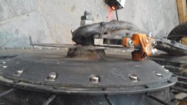
Got to the back and ran into "the wires rub on rotor bolts/swingarm" issue:

rsz_img_3298.jpg

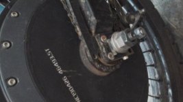
The wires currently run parallel to the swingarm, is it possible to reindex so the wires come out the facing the ground? I really don't want to re-temper the rotor trying to counter sink.

Hey guys so im also building an eeb frame and ran into this same problem with the wires way too close and rubbing. So here’s some pics of my mod it took a little trial and error but what I did was took off the reenforcing plate for the drop out and cut a notch in the main drop out this allowed the hub wires to come straight out. I then cut a smaller angled notch in the reenforcing plate to point the twords the front and so that it naturally goes in the direction it should along the bottom of the swing arm rail. I also taped up the wire cover on the QS 205 real tight with electrical tape to keep it tight and put a zip tie round the motor spindle to keep wires tight and away from rotor bolts.
 

Attachments

  • 13C5E219-B836-4462-85DA-558126CBF5B8.jpeg
    13C5E219-B836-4462-85DA-558126CBF5B8.jpeg
    24 KB · Views: 1,535
In addition to countersunk allen bolts, red loctite, and filing the dropout, use a zip tie around the wiring loom to the dropout/frame.

Your last picture was extreme where you cut a major part out. I didnt have to do that, i tried to avoid that. I see you had no choice but you didnt know you didnt have to.
 
That style of brake rotor is very thick and makes it even harder to make wires fit. I took the "easy" way out and run my setup without real rear brake and have variable regen on rear brake lever. Most part its just like normal brake but it has just a little lag and it cuts out if battery is full and just before bike stops. Or if controller or bms desides that something is wrong. Fine for normal riding but if you want wheelies and stuff not recomended by me :mrgreen:
 
harmonist said:
I thought the same about the blue seal as well! If you look at the rear shock you'll see its got the same slidey rubber piece as well. I also used a rubber hammer to tap the top brace off :)

Is that for setting sag? I’ve ordered my bike frame motor wheels and forks etc all from Alibaba.com.... waiting now since April 29th when it shipped from China ... how long does this wait take? I m gOngi cray z lol!
 
Do It like this - cable exit from the rear -it's not advisable to cut bits out of the arm as you need all the material you can get to stop the axle turning due to the torque.
 

Attachments

  • 20200531_2107341.jpg
    20200531_2107341.jpg
    27.7 KB · Views: 947
  • 20200531_2107441.jpg
    20200531_2107441.jpg
    31.6 KB · Views: 947
  • 20200531_2107511.jpg
    20200531_2107511.jpg
    24.9 KB · Views: 947
  • 20200531_210654a.jpg
    20200531_210654a.jpg
    31 KB · Views: 945
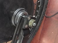
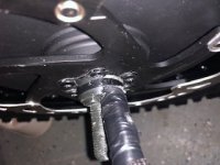
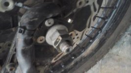
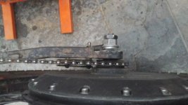
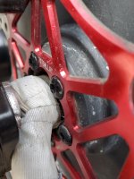
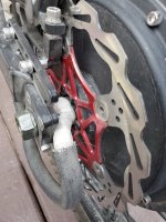
I too struggled with rear brake rotor interference with the motor's electrical harness on my EEB build.I wasn't willing to run without a rear friction brake so here is what I came up with. It's not pretty but it works and no structure has been compromised.

-Two specially cut "C" shaped washers on the LH axle space the wheel farther from the LH trailing link giving just a little more maneuvering room for the electrical harness.
-The harness is pulled tight to the axle as it exits the hub using fibreglass tape to keep it away from the brake rotor.
I also used aircraft lockwire with an antichaff/insulation wrap to assist the tape in keeping the harness hard against the axle until its clear of the brake rotor.
-The harness is run rearward until clear of the frame. This is not ideal but I think it is a safer routing to prevent rotor interference.

20200602_182912_resized_1.jpg
20200602_182903_resized_1.jpg
20200602_183023_resized_1.jpg
 
Nice build!

I got back to this project over the last couple days. Hope to finally sort out some odds and ends.

Like most good projects, are they ever REALLY done?
 
Back
Top