Any advantage of one layout over the other?

MJSfoto1956

10 kW
Joined
Jul 28, 2010
Messages
960
Location
Boston, MA
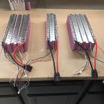
So I'm designing a 10s8p battery pack and it has become obvious that once your matrix gets large enough there are different legitimate ways to "wire them up" using a parallel-cell/serial-string methodology. Given that the end result is the same, is there any benefit of one layout style over the other that I might be missing?

Thanks!
Michael

10s8p layout comparison.1300.jpg
 
The one on the right should be able to flow more amps with copper soldered along the final strip, as there's lower series resistance than the left, and both leads come out the same side which is sometimes a plus.
 
Voltron said:
The one on the right should be able to flow more amps with copper soldered along the final strip, as there's lower series resistance than the left, and both leads come out the same side which is sometimes a plus.

A great description -- thanks!

M
 
On the Right
Discharge is somewhat uneven.
For equal discharge from each cell one of the discharge terminal should me moved to the opposite side.
You want equal length electrical path for each cell.

10s8p.jpg
 
The one on the right is a far better design....best I have seen and the way I have built all of mine in the last 4 years. Best current sharing...ask the pros!

Tom
 

Attachments

  • 87C22ABC-7EFD-40A2-BD47-B9C311080995.jpeg
    87C22ABC-7EFD-40A2-BD47-B9C311080995.jpeg
    155.3 KB · Views: 2,224
DrkAngel is correct: the discharge leads do need to be at opposite ends of the pack to ensure good current-sharing across all cells.

With this small change it is a pretty good layout, it's just awkward having to run one discharge wire along the length of the pack to join up with the other at the main connector.
 
.
..............................................
Updated alternatives


Mea - Left
Bottom banding indicated by added black lines.
Double banding on top segments recommended for optimal current flow.
 
Down side to outputs being on opposite sides are then you have to run one lead way longer than the other. So anyway you look at it one lead or polarity will have more resistance than the other. I doubt there are many designs that the controller could be placed dead center of the pack keeping all things equal? One could argue there would be more resistance through the longer lead than the flow of current through the pack. I personally would always have leads exit the same side and keep as short as possible.

Tom
 
The resistance of the discharge leads is pretty insignificant compared to the resistance of the pack (all the cells and their interconnects) so having one lead a bit longer than the other will make no real difference. You're also pretty unrestrained in making the leads as thick as you want to minimise resistance compared the other components of the battery.
 
As already mentioned the RIGHT handed design is the better one, and it probably can't get any better.
I would even go so far to wire the power wires to the middle of the pack and not the ends, or use two thinner wires and wire them at one and two thirds of the whole length. You may call me MONK if you like :bolt:
 
DrkAngel said:
Updated alternative

Bottom banding indicated by added black lines.
Double banding on top segments (of left) recommended for optimal current flow.

file.php


Redrawn "Best" on right is the best possible with identical draw from every cell.

Redrawn "Most Ergonomically Acceptable", on left, is near as good, when double banded across top connection.

Either of these is much better than anything else mentioned or shown!
 
I agree either of those layouts will be fine as long as the end cell groups have heavy parallel connections.

What kind of current are you expecting? Layout considerations are less important at lower power levels.
 
fechter said:
I agree either of those layouts will be fine as long as the end cell groups have heavy parallel connections.

What kind of current are you expecting? Layout considerations are less important at lower power levels.
I refer to the end parallel connections as "Rails" and make them as heavy or heavier than the battery "leads" (output wires).
 
fechter said:
What kind of current are you expecting? Layout considerations are less important at lower power levels.

I'm aiming for a 20s20p 72V 68Ah pack (the diagram shown is just 1/4 of the whole battery)

M
 
fechter said:
How many amps?

Not 100% determined at this juncture. My thought was to limit things to 80A max on the battery side, hence the 80A circuit breaker (see attached diagram). Pretty sure this won't be an issue for the QS 273 8000w hub motor. Note that the PowerVelocity 20kW Controller can handle 200A.

M
 

Attachments

  • Waterproof electrical box.1200.jpg
    Waterproof electrical box.1200.jpg
    147 KB · Views: 1,701
With a 200A controller, you will need an absolute minimum of >200A fuse!
200A fuse "burns up" at 200A, near 200A there is excessive heat and resistance.
300A recommended.
 
DrkAngel said:
With a 200A controller, you will need an absolute minimum of >200A fuse!
200A fuse "burns up" at 200A, near 200A there is excessive heat and resistance.
300A recommended.

AFAIK, the PowerVelocity controller is programmable. You set the max amps via their bluetooth app. It is "capable" of 200A max, which I have no intention on using.

M
 
That should work well. Depending on your cells, you might be able to run 10kW without overheating. A 80A fuse or breaker is supposed to handle 80A all day and will only trip or blow when it gets somewhat above that. I like the solar circuit breakers but they are large.

Yes, you can program the battery current limit with the PV controller. I have a smaller version, but the programming is the same. I've have very good results with it.
 
That looks good. I'd go for 100A. The controller is supposed to limit to below that. The breaker should only trip if something shorts out.
 
Why not 125A if breaker price and size is the same?
Have you bough one? Good one? Recommend?

I'm looking for breaker too.
These are very nice but 63A. Nice because I can see inside. I mean its not like you will watch a lot; transparent with aim to inspect components or it is just to attract potential buyer.
https://www.ebay.com/itm/1-Poles-DC-Circuit-Breaker-C3-63A-DC12-100V-DZ47-for-Battery-Motor-Photovoltaic/113457594835?_trkparms=aid%3D888007%26algo%3DDISC.MBE%26ao%3D1%26asc%3D20131227121020%26meid%3Dee8b2454fd6340d69ad817a51c38a9a3%26pid%3D100009%26rk%3D1%26rkt%3D1%26sd%3D113065239849%26itm%3D113457594835&_trksid=p2047675.c100009.m1982

It takes time till breaker worms up and break the circuit. Or does it increase resistance before it breaks the circuit. It might be that's why you need more or equal Amps breaker as your controller max Amps.
I know that 63A breakers are used with 72v 150a controllers & 72v batteries and 3kw motors. Possibly short amp bursts over 63A are tolerable by a breaker. It might depend on a breaker.
 
Back
Top