bluetooth BMS?

ElectricGod said:
One more post on this BMS...

Small components, board top:
The large IC in the orange box is the charge controller. I don't know what part it is. The red box looks like 2 DC-DC converters. Probably one supplies 5 volts and the other 12 volts. Under the grey thermal gap filler in the green box is a bunch of SMT resistors. I can't see them so I have no idea of their size or wattage. I bet they are .25 watt resistors or less. That would imply this BMS can do a max of about 1 amp balance current. What are those 2 connectors in the blue boxes. I have some 7S smart BMS's that have input and output connectors on them so that multiple BMS's can be daisy chained together. This allows you to have up to 22 of them in series or 154S. These connectors may serve the same purpose or they may support external balance boards so that this one BMS can control far more than 16 cells. The left connector has 3 pins and the right one 5. I see a single opto-isolator on the board and space for 3 more. Maybe the 5 pin connector is for an LCD in which case a single opto-isolator is all that's needed. If the 5 pin connector was used for connecting to another BMS, then TX and RX would be needed and that means at least 2 opto-isolators.

board%20top%20small%20components.png
According to the post from Taobao, the smaller blue box is for connecting temperture sensors. The bigger blue box is the "CAN 485 / 4P" communication port which I do not know what that is. Also, it can be used to turn the BMS on and off.
 
tmho said:
ElectricGod said:
One more post on this BMS...

Small components, board top:
The large IC in the orange box is the charge controller. I don't know what part it is. The red box looks like 2 DC-DC converters. Probably one supplies 5 volts and the other 12 volts. Under the grey thermal gap filler in the green box is a bunch of SMT resistors. I can't see them so I have no idea of their size or wattage. I bet they are .25 watt resistors or less. That would imply this BMS can do a max of about 1 amp balance current. What are those 2 connectors in the blue boxes. I have some 7S smart BMS's that have input and output connectors on them so that multiple BMS's can be daisy chained together. This allows you to have up to 22 of them in series or 154S. These connectors may serve the same purpose or they may support external balance boards so that this one BMS can control far more than 16 cells. The left connector has 3 pins and the right one 5. I see a single opto-isolator on the board and space for 3 more. Maybe the 5 pin connector is for an LCD in which case a single opto-isolator is all that's needed. If the 5 pin connector was used for connecting to another BMS, then TX and RX would be needed and that means at least 2 opto-isolators.

board%20top%20small%20components.png
According to the post from Taobao, the smaller blue box is for connecting temperture sensors. The bigger blue box is the "CAN 485 / 4P" communication port which I do not know what that is. Also, it can be used to turn the BMS on and off.

CANBUS is super common in all sorts of uses where you need decent digital communications. There is probably an LCD and a USB adapter that can plug in here.

I bet 2 wires...ground and enable are used to turn the BMS on/off. Then ground and the other 3 pins are CANBUS.
 
I have the xiaoxing bluetooth bms. But i have two 10s bms wired in series for 84v peak. Everything has been working fine for a while... but today on the way home... right at the end one batt cutout on low voltage... but i continued on for a little bit at low power i.e 30v and got the dreaded burning smell and heard a pop lol

Strangely everything still seems to work but i am wondering what may have failed and what needs to be checked ? If the ouput mosfet on one bms is off and on the other its on where would the current flow and cause this ? Maybe one mosfet failed and the rest are still ok ?
 
Gab said:
I have the xiaoxing bluetooth bms. But i have two 10s bms wired in series for 84v peak. Everything has been working fine for a while... but today on the way home... right at the end one batt cutout on low voltage... but i continued on for a little bit at low power i.e 30v and got the dreaded burning smell and heard a pop lol

Strangely everything still seems to work but i am wondering what may have failed and what needs to be checked ? If the ouput mosfet on one bms is off and on the other its on where would the current flow and cause this ? Maybe one mosfet failed and the rest are still ok ?

In series...hmmm...are you using P- or C-? If you are,then those are probably NOT 100V mosfets on the BMS. I would bet they are dead shorted now. IF you use multiple BMS in series, then don't use the mosfets at all. You will effectively have balancing only.

2 things that are bad about using the mosfets on smaller BMS's in series.

1. It is probable that 1 BMS will shut off and the other won't at the same time. This applies the entire pack voltage across the other BMS's mosfets and of course they burn out.
2. You need the entire pack to cut off at the same time. Otherwise, you are not really shutting down in a fault situation.

You would do better to NOT have the mosfets at all than to have them in use in a series arrangement.

That or get a BMS that actually supports your cell count.
 
Hi guys

I bought this bms few months ago and when I was trying to connect my phone via bluetooth I can't establish connection

was working fine for 5 months

I can see bms is working while charging but I can't connect to my androind phone

I unpluged all cables from the battery and left bms for few hours

I'll connected again.
turn on switch and I can hear one beep - lights were on the bms

I go to my phone settings and I can see bms in the bluetooth device list

So I was trying to pair bms with phone with 0000 or 1234 code

no success

I did not change anything in the settings before

how to restore to factory bms settings?

I am not using lcd screen just a phone

is it possible to fix that somehow

please advise

thanks for You help

Lucas
 
izeman said:
As you didn't include a circuit diagram on how you wired everything it's hard to make assumptions.

For rhe wireing its just wired like two separate batts. The only connection between the batts is the main output plus and minus. The reason i have it liue this is that sometimes i use the batts at 36v. The bms normally only see 36v. And everything has been working fine for a while, its just now on low voltage cutout that i kept it running after one bms cutout.
 
lukas999 said:
I go to my phone settings and I can see bms in the bluetooth device list
So I was trying to pair bms with phone with 0000 or 1234 code
no success

You are not supposed to pair it with your phone.
Open the Little Elephant App and wait for the App to recognize the BMS.
It will say connectable Xiaoxang BMS, just tap on that and it should connect.
 
izeman said:
eee291 said:
Open the Little Elephant App and wait for the App to recognize the BMS.
Maybe we shoud call it HADOOP, as this is the company they stole the icon from.

Screenshot from 2018-12-19 11-07-32.png

Coincidence...pure coincidence.
 
I left the USB to Serial box connected for a month (I don't really remember the date) and now I'm seeing this:


Disassembled the pack and checked cell voltages. They read from 0.1 to 1 volt.

So, this killed my battery. I'm angry and frustrated, these BMS were great until today.

I can't believe the BMS does not have protection for a case like this. What happens with the bluetooth module? I think it enters sleep mode... but if you leave it years plugged... it will kill your battery too?

Any comments?
 
I saw something similar. Posted it some month ago. I was expecting the BT module not to enter sleep mode. But i guess that's not what's happening.
There must be some settings wrong that cause the BMS to try to balance until the battery is dead.
Please post your other settings to check them.
 
I had the BMS go into a balancing loop when I set the Balancing precision to 0.001V. Setting it to 0.004V solved it for me.
 
eee291 said:
I had the BMS go into a balancing loop when I set the Balancing precision to 0.001V. Setting it to 0.004V solved it for me.
Yes, something like this. If you set it to "always balance" and set balance precision too low it will never stop.
This imho is a design flaw, as it should stop at "balance voltage start voltate" and at cell's LVC latest. :(
 
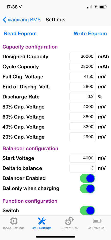
Izeman, you settings look more agressive than mine. Your delta voltage for balance is 3 mV and mine is 30. My start to balance voltage is lower but not much. I still think the Serial2USB box sucked all the battery energy, probably bypassing the protection mosfets. I don't have the skill to demonstrate it though.
BTW, which app are you using? My android app looks very different.
 
trazor,

I understand how frustrating that might be with all the resources we put into this. I really wanna help but I am very new to this BT BMS thing and still in the learning process.

Since the app and the BMS's capability to adjust various parameters, it is quite complicate by the nature of it's tasks. Users can mistakenly set something wrong without knowing it - even experienced users.

Something came to my mind that we should do, or should have the BT BMS do it for us, to prevent future threats like your case :

1) Allow the owner to monitor the pack remotely (via app) not just BT that we have to be near-by or in the same room.
2) Be able to alarm and send alarm remotely (buzzer, e-mail, via app, etc.)
3) Allow the owner to remotely command the BMS to do something like : shut-down the pack, start/stop balancing, etc.

Or anyone knows how to do that please share. Since it will be very beneficial to the community.

I have been thinking about the above for a while. Your case just came up - then I think should post this.
 
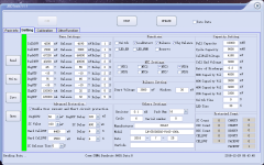
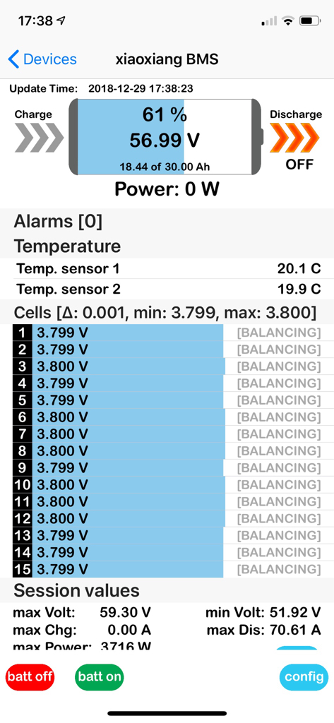
Does anyone happen to know what is going on with my bluetooth BMS? I have the board from LLT and for some strange reason it will only balance on the odd cells groups not the even ones. I have tested to make sure it is not a hardware fault by opening the even groups via the PC software and the even groups appear to balance just fine but it will not do it automatically.

I have 2 of these boards so I am used to the settings for them but I have tried everything I can think of to get it to balance on the even groups with absolutely no luck. Every now and again very briefly it will look like it's balancing on the even groups but it will just flash up for a second and then stop. I've tried all different delta settings and balance voltage settings plus have cycled the settings with the PC software rather than the bluetooth app but it still will not work, it will only work when you manually do it on the "debugging" part of the PC software by clicking "open even groups".

Any help would really be appreciated.

Thanks
 
A couple of questions before I hit the order button. I have a 24s 10AH lifepo4 pack, and while I generally only use 20A to 30A, I sometimes burst to 80A for a short while. Will the 100A version of this BMS be able to handle that for me or should I go for a higher amp version?
https://www.ebay.com/itm/8S-24S-Lifepo4-li-ion-Lipo-Battery-Protection-Board-Smart-BMS-Balance-Bluetooth/192713045620?hash=item2cde97b674:m:mmYGtW2LCsV0HOzua9mBVkw:rk:1:pf:0&shqty=1#shId

Then did you guys get a wiring harness with it or did it all have to be built up individually?

Thanks
 
The 100A version is more than enough for 80A bursts.
I'm not 100% sure about the balance wires on that BMS version, but looking at the pics you will have to make it yourself.
It's not difficult at all you just have to plug the pins into the connector.
 
Back
Top