Axiom: a 100kW+ motor controller

Yeah, icestudio was the find of the month for me. A single 80mb executable instead of a bazillion gb, and so few buttons. Its super tempting to go with microsemi, even the non-radhard are quite radhard, and oh the flash memory... But me and my team are the ones who will struggle with the fpga software, and its more tempting to avoid the struggle.
I'm already testbenching some delta sigma HDL and SPI slave, I think thats how far I'd go with the opensource toolchain.

The simpler IDE also lowers the entry barrier to actually use and build this hardware, its not that common to know about HDL
 
did some digging. i really like this board: https://tinyfpga.com/ the BX variant.
i'm pretty sure i read somewhere he is working on getting icestorm supported for this board.

i think for hobby projects this is perfect! thanks for sharing!
 
Ice40 kit ordered, if the test turns alright I'll add it to the schematic/layout for RevC.
 
I got my hands on a super old resolver so I thought I should test the resolver to SPI circuit. Only one of the customers had a motor with integrated resolver and I don't know much about their setup.

My build had a wrong part# for the reset monitor, they come in the same package with different pinouts, go figure. What made me struggle was a cold solder joint, I was too confident because the board was machine assembled but meh.

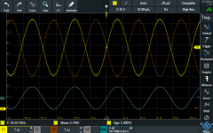
resolver output.png

So 10Vpp across the resolver reference at 20KHz. Looks good. Saturday we'll be hooking up the resolver to the board, it is intended for 400Hz systems so my 20khz could give some headaches, we'll find out.
 
I will tell my grandchildren about the time I wrote some resolver support code and it worked on the first try.


View attachment 3


To provide support to the SPI resolver interface I based my code in benjamin's code for an SPI encoder IC which is not so different to our resolver chip, we just need some extra control signals. One is the SAMPLE that latches the current position so it can later be read over SPI. The other is RDVEL that selects between rotor position and velocity.
These extra firmware lines are only available when the project is configured for this board. (#define HW_VERSION_PALTA)


View attachment 2
CLK looks funny because the logic analyzer sampling rate is near the 4MHz SPI CLK frequency.

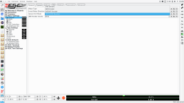
Then you need to add a way to select this type of position detection within the GUI. For that you need to tweak a bit the GUI source, you just need to install Qt creator and clone vesc_tool repo. I used to be a competent Qt programmer in a previous life so I could find my way to adding the menu item and the motor configuration enum to the GUI. Something I did not take care of is hiding this extra resolver type when the user connects a regular VESC which obviously doesnt come with resolver support. I guess benjamin has a clever way to deal with that.


resolver config.png


The position read requires a falling edge of the SAMPLE signal to latch the postion register. I assert that at the same time the ADC is sampled, because I want the picture of voltages, currents and position to be simultaneous. However, the current SPI implementation surprisingly is a bitbanging approach, super low performance and cpu consuming so I can't get the position read on time, it is always available in the next control loop iteration (50us later).
This is alright if accel is not really high, but migrating to a full DMA with 20MHz SCLK (1us readout) is high in my list of priorities so we can actually have simultenous V, I and postion. There is some position error estimation in place but I'd avoid that if I can.


DMA SPI is not an easy task, I'm used to work barebones but here the rtos manages these things and I'm not familiar with ChibiOS. I think that once I configure SPI3 the OS will handle it in a DMA-way.
So, in theory it is working. I say in theory because my 400Hz resolver is no good for this, scope captures of sin/cos look really bad, neither of those get close to 0Vpp in a full turn, but the digital interface is working well, and the IC properly detects DegradationOfSignal and LossOfTracking.
I'd call it a day and move on to the FPGA which I'm unboxing.
 
FPGA is a go. Toolchain works as expected, pretty nice for the simple stuff. One of these days I'll check that PLL correctly boost freq to 200+MHz for SPI oversampling. What I have in mind is to keep this safety logic open, and later down the road develop more complex features in the fpga that could be firmware-upgraded, like one of those oscilloscope licenses.

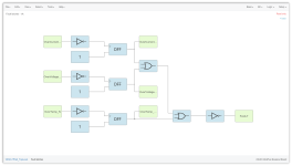
So here's the basic HDL testing, you define the logic, our good'n old latches that we used to have as discrete logic


LatchLogic.png


I want that even a brief pulse in any input gets latched in a way that we can see an LED showing which over* condition was triggered, and I also need a general FAULT to mute all the PWM logic and notify the MCU. This FAULT output is active low because the FPGA has great current sinking capability, and I want to strongly drive the line to 0v.

When you have the digital design ready you simulate it and you get something like this


View attachment 1


So I simulate a fault event in the Voltage sensing, it latches the OverVoltage LED ON and the FAULT line until a reset happens. This is the simplest case of a single scenario, the complete testbench had larger coverage.

When simulator does what you expect you move to the actual hw, so here an example triggering OverCurrent, even including some input signal bouncing


The FPGA pins can be configured with internal pullups, which come in handy here. Also the board comes with a BFR LED (a Big Flashy Red LED) connected to our FAULT so you get a tiny bit blind every time you trigger a fault.

That's how far I went in the last hour today at work. Next time I'll validate PWM overlap and PLL because I need instruments.
 
Today I wrote the code needed to configure the FPGA from the MCU. This way the VESC firmware also stores the FPGA bitstream and configures it on startup.

There are 2 reasons to do it this way
* Its the easiest way to get an FPGA HDL upgrade. If you go through the usual path of storing it in an external flash memory, how do you reprogram that external memory? You'd need connector, programmer, etc. The way I did it if you have the latest firmware it will configure the lastest HDL code on every boot, and firmware is upgraded directly from the GUI:


* If you use an external SPI flash memory, the FPGA boots in SPI master mode and you'd need to swap SPI pins after configuration because you can't easily change from master to slave, and I intend to treat the FPGA as an MCU slave, a sort of peripheral. If the FPGA is always a slave, there is no need for pin swapping.

Tested the firmware and it works, MCU alone sends the bitstream and the latch logic goes live in a few millisecs. I'm running the SPI at low speed (~3MHz) to avoid issues, my big VESC and the FPGA eval kit were connected with many flying wires. Thats the reason why there is so much overshoot in the edges.

First bytes of the FPGA bitstream
fpga mcu config.png


On other news, benjamin merged the resolver code support into his local branch, so eventually it will be on github.
 
Hey marcos, i’m part of the Missouri S&T Formula Electric car design team. We were thinking of running two 25kWh hub motors in the front of the car along with two 50kWh hub motors in the back. We have some 600V 150A IGBT’s that work. We’re hoping to use an open source motor controller to drive these, and this project looks very promising. Would this be a good idea for our use, or is there some other project or motor controller you could point us in the direction of? If we can get to use this we have a dyno in shop we can use to test the controller on some real life motors, and move up the description to TESTED. Below is our website if you wanna check us out.

https://formulaelectric.mst.edu/
 
Hoonta said:
Hey marcos, i’m part of the Missouri S&T Formula Electric car design team. We were thinking of running two 25kWh hub motors in the front of the car along with two 50kWh hub motors in the back. We have some 600V 150A IGBT’s that work. We’re hoping to use an open source motor controller to drive these, and this project looks very promising. Would this be a good idea for our use, or is there some other project or motor controller you could point us in the direction of? If we can get to use this we have a dyno in shop we can use to test the controller on some real life motors, and move up the description to TESTED. Below is our website if you wanna check us out.
Cool,
I'd like to support a project like that, and this controller is designed for abuse unlike most controllers out there.

Dozens of people asked me for boards and I've been holding their horses for a while, now I think we're ready to manufacture a very small batch.

Yesterday I tested a major hardware change on RevC that solves an issue with position observer using IGBT's and motor seems to run fine. I need to make an algorithm change to accommodate for my hw change, but even without it the motor is running, so I should shift gears and get this moving.

One thing your motors will need for a high performance application is a rotor position sensor, preferably a resolver (exc,sin,cos) because firmware already supports it. A BiSS encoder would work as well, hardware is ready but needs firmware support.

I want to make the full release once documentation is ready, we made lots of progress:


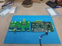
View attachment 1


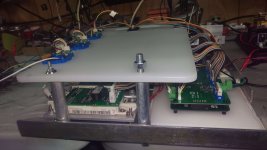
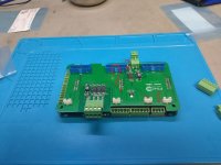
That is a closeup of RevC, with the discrete logic replaced with the FPGA (which I'm loving btw). Also note the RF connectors, they are super valuable for debugging. VESC firmware and GUI comes with some data acquisition, but can't beat this:


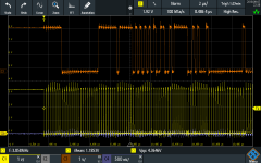
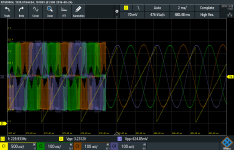
SCR01.PNG


In this case I'm probing the phase voltage signals right at the MCU ADC pins, and yellow is a DAC output.
As a hint, I'm debugging the slight change of slope in the observer position (yellow waveform) right after the motor is released. I can send any MCU variable to the DAC's channels, in this case is the observer phase.

Feel free to PM me, I'm leaning towards EconoDual modules, so any other module package will require some customization.
 
Hey Marcos,

Just finished reading through this thread and following your progress. Love the project! I'd like to not only build a VESC-controller, but also help out with any loose-ends on the hardware or embedded side of things (if needed).

The repo (https://github.com/paltatech/VESC-controller) hasn't been updated in a while. Any plans to do so in the near future? Anything my self or other can do to help with documentation?
 
And I have a problem ...S.O.S...
when i try to do (motor setup wizard) then i used option BLDC or FOC its not detect Parameters ...
and in the first photo below right, I volts they are not correct there is about 5 volts the difference between what I have on (capacitors, battery) ... on pic is 43 V in real is 48 volts ...

maybe you need more information ?

IMAG0286-min-min.jpg
IMAG0283-min.jpg
 
maholli said:
Just finished reading through this thread and following your progress. Love the project! I'd like to not only build a VESC-controller, but also help out with any loose-ends on the hardware or embedded side of things (if needed).

The repo (https://github.com/paltatech/VESC-controller) hasn't been updated in a while. Any plans to do so in the near future? Anything my self or other can do to help with documentation?

Welcome along, and stay tuned. Design is ready, I'm quoting a pcb assembly in several houses. I want to validate the fabrication files because I could rework a few boards, but I can't deal with 50 bad boards, hence the small test sample. Once released (when I'm confident it is a safe design) any help will be welcomed, there are several ways to get this project improving, especially in the firmware/testing side.

Abricosvw, nice build!
About that 5v difference, I wouldn't worry too much, if your fullscale is 600V, you have <1% error, and these isolated amplifiers have a rather poor offset spec.
One thing you can try is using AMC1311, they work better for voltage sensing, you need to change the resistor divider because they have gain=1 instead of the original gain=8.2.

I didn't quite understand what is failing for you, but here's some pointers.
Double check the polarity of the current sensor. When you drive current towards the motor, the voltage at the mcu adc pin measuring current should go higher. If it goes lower you can flip the hall sensor or flip the signal wires.
This might be a reason why the board measures 0 ohm. Get this polarity right before trying to measure resistance, I've seen a wild current spike during parameter detection when I installed a sensor backwards.

Another thing that gave me troubles is the HALL sensor reference. Its super wimpy, can't drive more than a few uAmps and its not suitable for connection to Isense(-). Let me know if thats your case.

You can make the motor spin by hand and trigger "sampled data" to check all phase voltage sensor are ok, you should see the motor generating 3 sinewaves.

If the sensing is right you can start with the FOC parameter detection. Resistance and inductance measurement worked ok in my tests, using vesc GUI. There is a trick to have much better precision: connect the board over USB, in the left sidebar head to VESC Terminal and type "help".
Tons of useful commands in there, and try "measure_res 30". That will measure resistance flowing 30Amps through the motor. Increase that number and you should see the mOhms to start converging. I run 150 Amps through my motor for resistance measurement. Its noisy! The GUI algorithm increases the current in several steps, for some reason it never reaches currents high enough in this larger board.

I was very close to write a post here about how impossible is to measure 14mOhm resistance with a 600V voltage sensor, but then I found a schematic mistake, re-tested and measured 15mOhm. I still don't entirely understand why resistance measurement is working that well, so I will follow with interest your case.

If you can measure resistance and inductance, get prepared to spend some time trying different I, D and w parameters for flux linkage detection. My motor required I>15A to be able to spin the motor, I can't remember the duty and ERPM though.
The idea is that you set those parameters so the motor spins. Once it is spinning the motor is released and flux linkage is measured. The difficult part is to make the motor to spin, firmware tries several times with multiples of the parameters you set and that works for the original vesc, but not on this board, or at least with the combination of my board and my motor.

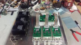
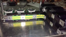
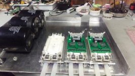
Something that worries me about your build is the connection between the DC link capacitors and the IGBTs. From the image it seems to have a large current loop area
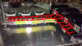
loop area.jpeg

Every nanoHenry that you add between DClink and IGBT will greatly increase the voltage overshoot while switching, and those overshoots will instantly kill the switch ig you happen to be anywhere close to your 650v limit.
Can you make an assembly like this?
http://electronicsmaker.com/wp-content/uploads/2015/04/Infineon-Fig-5.jpg
And IF that is not enough you could place snubbers at each IGBT.

Otherwise you will need to decrease a lot the rise/fall times to avoid overshoots, and switching losses will skyrocket.
 
HI
I found a couple of mistakes ...
one of them seems critical ...
in the photo below it is marked as number one ... I messed up two wires in the middle ...
is it possible to destroid amc1301 ??? number two ???
i ordered AMC1301DWVR and AMC1311BDWV
1541116420572 - Copy.JPEG

Current Transducer has current flow directions in the photo below ( Vout is positive when Ip flows in the direction of the arrow )

I added these capacitors two 47nf between 2-3 2-4
between 1-2 cap is origenal on pcb 100 nf
thanks ...
New Bitmap Image.jpg
 
If you connected the iso-amp diff outputs backwards there is no danger. In the worst case the microcontroller would read 0V at the DC link.
If you connected the iso-amp supply (0v and 5v) backwards, I would replace the part.
If in doubt, I would replace the part as well, any mistake can lead to an expensive blow.

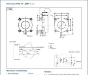
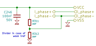
About your hall sensor, datasheet says you should load your Vref with >200kOhm, but the conditioning circuit loads it way more (2kOhm or so).

You can set the reference with an external -and strong- resistor divider. I use 220 Ohm for example, some day I'll try higher resistance.
stronger_Vref.png
With this divider you can leave the Vref wire unconnected. Offset is corrected on startup anyways.
 
hi
maybe it looks like it works AMC1301 and I see battery voltage but with an error ...
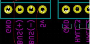
also it seems to me in the photo messed up with designation ...
#2.jpg

also i found my mistake with LM1117 I have 3.3 volts on PCB ... i ordered fo 5V i think its helping...:)))


Thanks ...
 
Woops, good catch that silkscreen, thanks.

And yes, the iso-amp should work at both 3.3v or 5v, but its isolated power supply has a transformer with a turns ratio intended for 5V input operation. If you supply it with 3.3v I guess the isolated side won't reach the 5.0v I intended.
 
hi
i have a problem
on first pic we see (main board GATE_DRIVER_CONN_U) connector ... power supply to this connector 24V ......
#1.jpg
on in the second pic we see (power_integrations_interface GATE_DRIVER_CONN_U) connector ... power supply to this connector 15V ..
View attachment 1
on the third pic we have a problem with volts 15-24 ?
#3.jpg
and that means 24V going to LM1117 which can hold only input 15 voltage ...(LM1117 died)
and that means 24V going to Integrated Circuits Gate Drivers which can hold only input 15 voltage ... ( i hope it's not roasted (((((((

or i doing something wrong ???
Thanks ...
 
First of all, change R74 to 110kOhm. RevA and RevB were made for a gate driver that works at 24V, but the gate drivers for EconoDual operate at 15V, I should have put a big warning on that regard in the adapter board files. The few boards I distributed were configured at 15V, and so is the unpublished BOM since RevC. There was a team that built their boards and I didn't hear any gate driver failure, now I wonder if they found about R74 before or after powering up the gate drivers. I do remember another team struggling with your gate drivers and it was because they used 12V and that triggers the undervoltage protection, jumping to 15V got them running.

With R74 change from 180kOhm to 110kOhm you change the supply output from 24V to 15V, that power supply was intentionally designed and tested to cover a wide range of input and output voltages.

I'd replace the LM1117 and give it a try. Proper way to go would be replace the gate drivers, but I understand they are expensive, so if I were you I would test carefully the gate drivers, you can charge the DClink, disconnect battery and try PWM'ing. In the worst case (faulty gate driver invoking a shoot-through) the short energy is limited to the energy in the DC link. It would be a good thing to also try a double pulse testing to ensure the gate driver protection is working.

I'm really worried about your DC link busbars, they have a large current loop and high parasitic inductance, you might need to change the gate driver resistors to slow down the dI/dt in order to avoid a destructive overvoltage during switching, but its almost the same amount of time reworking the gate driver resistors than building a busbar with lower inductance. I hope you can fix that, keyword for a google images search is "dc link laminated busbar".
 
hi...
I don't have a 110k resistor ... I added 270к to the resistor ...
and I think it would be nice to add a jumper for versions with 15v and 24v and small description on pcb why they are needed ...
 
and I think it would be nice to add a jumper for versions with 15v and 24v and small description on pcb why they are needed

Thanks for the input, what I originally had in mind is a software approach. Since RevC boards can measure gate driver supply voltage, and I want to be able te select some basic gate driver parameters from the GUI (dead time, max freq, supply voltage) so I could trip a software fault if voltage goes beyond the operating values. Its not perfect but I don't want to dynamically configure that voltage due to reliability concerns. In any case, this heavily impacts the GUI code and file formats so I need to talk with Benjamin about this, he doesn't know yet.
 
Added software protections for gate driver power supply output undervoltage and overvoltage. Set at 14.0v and 16.0v at the moment.

These voltage thresholds are hardcoded in the firmware the same way deadtime is configured in firmware. You can't tweak it from GUI, but you can't change the gate driver supply voltage without a soldering iron anyway.

If your gate drivers draw too much current and supply output drops, then your drive is shutdown AND a fault is raised and will show you that an undervoltage happened (tools->show faults). Its easy to stop the switching, what drives you nuts is not knowing why it faulted.
 
2nd place in pcbway design contest!

https://www.pcbway.com/blog/News/Winners_List_of_PCBWay_Second_PCB_Design_Contest.html

I'm pretty sure I would had a solid chance of winning the 1st prize if I had uploaded RevD instead of RevC, but $500 is very welcomed. You never have enough ice cream.
 
marcos said:
2nd place in pcbway design contest!

https://www.pcbway.com/blog/News/Winners_List_of_PCBWay_Second_PCB_Design_Contest.html

I'm pretty sure I would had a solid chance of winning the 1st prize if I had uploaded RevD instead of RevC, but $500 is very welcomed. You never have enough ice cream.

Congrats! Keep up the good work and try not to get sick on all that ice cream!
 
Hey marco, firstly thanks for such an interesting controller.

Secondly, i am bit confused please help me out in this situation. I am building an e bike featuring high power PMS motor with rating of 50kw. The operating voltage of motor is around 100volts and current draw is around 500amp peak and 200amp in normal situations. I am planning to build my own power integration part. So i choose IRFP4568PBF-ND as Mosfet and planning to use 2 of them in parallel and i am using NCP81075DR2GOSCT-ND as a mosfet driver. Would it be ok or i need to take something else in consideration. And also tell me roll of dc link capacitor and which capacitor value will be best in this scenario. I have not found any info about dc link capacitor on github please update it. And again thanks for such a great masterpiece.
 
Back
Top