
You are using an out of date browser. It may not display this or other websites correctly.
You should upgrade or use an alternative browser.
You should upgrade or use an alternative browser.
JP spot welder
- Thread starter riba2233
- Start date
I was thinking about use some server Power supply in parallel. Do you think they can handle?
If not, what about use 48v as a DC source? I can get a lot of power supplys for free they are 48v 50A, 2400w... I can parallel them, bit not sure if 48v is too much.
If not, what about use 48v as a DC source? I can get a lot of power supplys for free they are 48v 50A, 2400w... I can parallel them, bit not sure if 48v is too much.
tomjasz
1 GW
JOY! My backup welder arrived. THANKS!!!
JPWelder x 2
JPWelder x 2
Fidel said:I was thinking about use some server Power supply in parallel. Do you think they can handle?
If not, what about use 48v as a DC source? I can get a lot of power supplys for free they are 48v 50A, 2400w... I can parallel them, bit not sure if 48v is too much.
48v is too much. 12v is about the maximum.
Consider that on mine, I measured about 3,000A during the pulse at 12v. There has been some success using gigantic capacitors and a 12v supply. The average power is not that much so the caps can get recharged with a reasonably small 12v supply.
Fidel said:I was thinking about use some server Power supply in parallel. Do you think they can handle?
If not, what about use 48v as a DC source? I can get a lot of power supplys for free they are 48v 50A, 2400w... I can parallel them, bit not sure if 48v is too much.
Whoa whoa whoa
[youtube]pe_bkijv6f0[/youtube]
12V is max for lead battery, and 9V for lithium battery. Everything else is insta-death for the welder.
Also, welder pulls such high current pulses which could easily damage or destroy a power supply.
tomjasz said:JOY! My backup welder arrived. THANKS!!!
JPWelder x 2
You're welcome, and thank you for buying! :thumb:
fechter said:48v is too much. 12v is about the maximum.
Consider that on mine, I measured about 3,000A during the pulse at 12v. There has been some success using gigantic capacitors and a 12v supply. The average power is not that much so the caps can get recharged with a reasonably small 12v supply.
As always, right on point! 8) Thanks for helping :thumb:
sevillano1982
100 µW
- Joined
- Sep 16, 2017
- Messages
- 8
Ok ¿Como te hago el pedido?
Fidel said:Right now I'm using two 6v 180Ah PB batteries in parallel, and I get perfect welds.
But I'm moving my bench, and don't want to use those big batteries there. I think I'm going to see some capacitors? Any advise? Think about use 5v power supply.
I personally don't have experience with capacitors, I just know that they are bloody expensive if you want the good ones. (spoiler, bad ones do not work). However, if you read some older posts, you can see few examples of using small and affordable lipo packs for powering the welder.
sevillano1982 said:Ok ¿Como te hago el pedido?
Hi,
please see the update in the first post, thanks! Usually I take orders through private message.
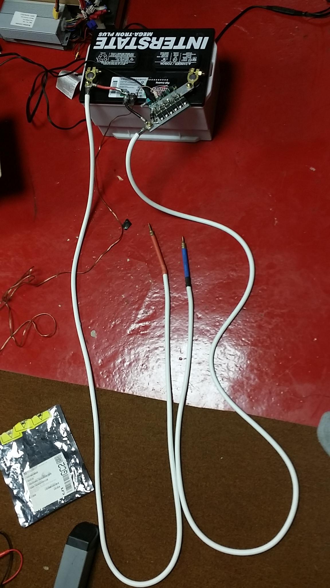
I'm going to modify my JP spot welder probe wires with 4 AWG superflex silicone wire. I will be cutting off the old wire and crimping on new wire to the probe.
Quick question, I want to make the length of the wires about 5 feet long or 1.5 meters long. Someone said in a previous post a couple of years back that if I used a diode between the Positive and negative of the battery and use a TVS diode between the two aluminum bars on the welder, that I could make the probe wires as long as I wanted.
Is this true, and do you see any issue with making the probe wires 5 feet long, will it affect anything?
Thanks.
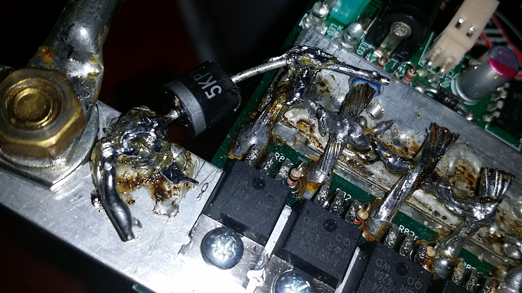
Here are the diodes I'm using to help with the avalanche current, and I believe these diodes will allow me to make the wires longer.
I will use this TVS diode between the two aluminum bars on the welder.
https://www.mouser.com/ProductDetail/625-5KP14A-E3?r=625-5KP14A-E3
I use this schotty diode from the positive and negative terminals on the 12 volt lead acid battery:
https://www.mouser.com/ProductDetail/IXYS/DSA300I45NA?qs=INK05T%2FwFA1xP1UqSh4eTw%3D%3D
Here is the discussion about the diodes, this post and later posts.
https://endless-sphere.com/forums/viewtopic.php?f=14&t=81400&start=500#p1208273
Quick question, I want to make the length of the wires about 5 feet long or 1.5 meters long. Someone said in a previous post a couple of years back that if I used a diode between the Positive and negative of the battery and use a TVS diode between the two aluminum bars on the welder, that I could make the probe wires as long as I wanted.
Is this true, and do you see any issue with making the probe wires 5 feet long, will it affect anything?
Thanks.
Here are the diodes I'm using to help with the avalanche current, and I believe these diodes will allow me to make the wires longer.
I will use this TVS diode between the two aluminum bars on the welder.
https://www.mouser.com/ProductDetail/625-5KP14A-E3?r=625-5KP14A-E3
I use this schotty diode from the positive and negative terminals on the 12 volt lead acid battery:
https://www.mouser.com/ProductDetail/IXYS/DSA300I45NA?qs=INK05T%2FwFA1xP1UqSh4eTw%3D%3D
Here is the discussion about the diodes, this post and later posts.
https://endless-sphere.com/forums/viewtopic.php?f=14&t=81400&start=500#p1208273
I've been told that the diode will prevent a voltage spike due to inductance, but it also adds resistance to the circuit. If the diode survives, it will get hot.
I'd like to see what really happens. Please post if it works...
I'd like to see what really happens. Please post if it works...
The diode goes across the leads so won’t add any resistance. I’m using one on mine with no issues.
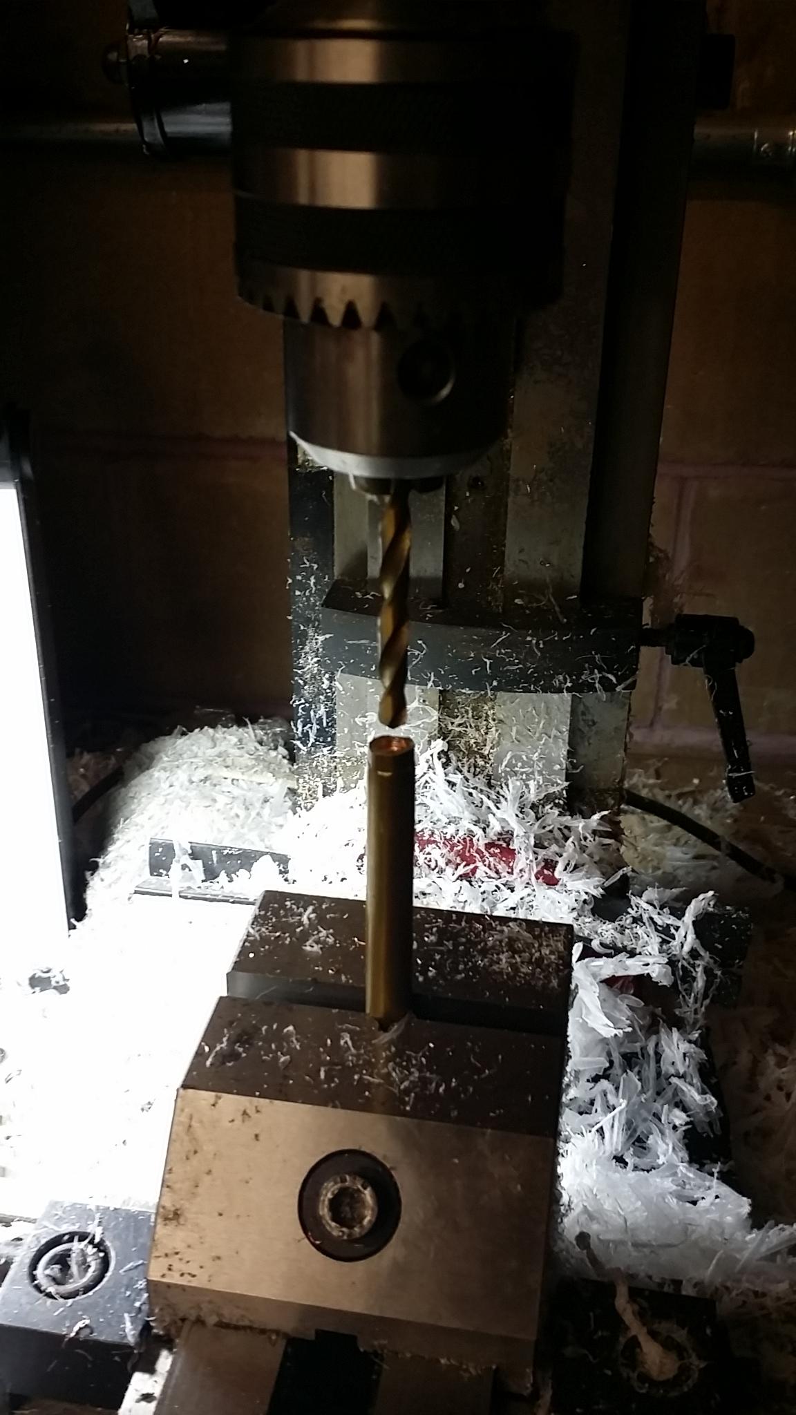
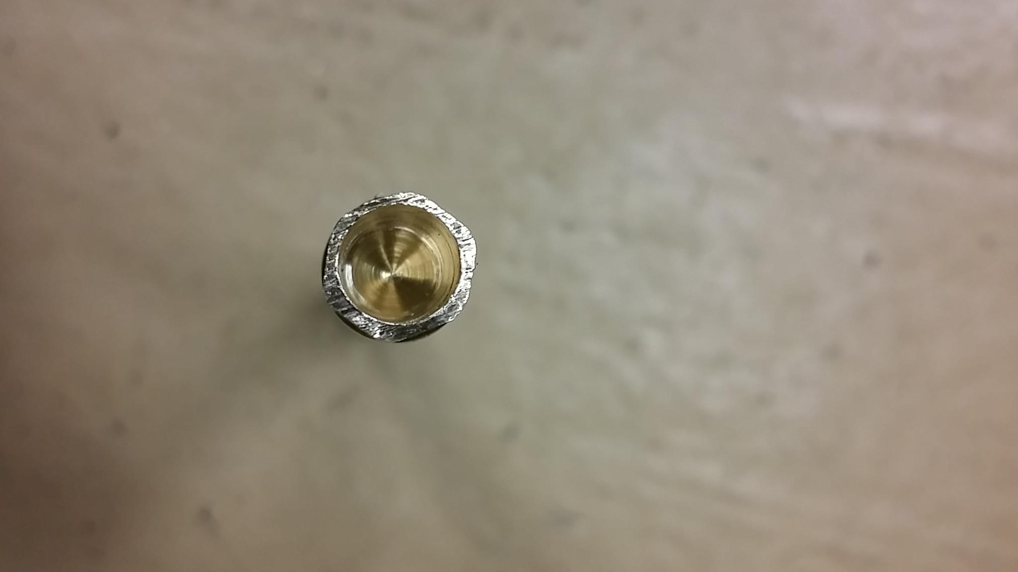
I'm still hoping someone can give some advice about the last question but another question came up.
When trying to get the 4 awg wire into the probes by drilling it out, it has been a bit difficult because the 4awg wire is thick.
I'm not sure how good my crimp is because of the thinness of the probes wall and I am not sure if I drilled deep enough because I screwed up the first crimp by using too small of the crimper die which broke/cracked the crimp by crushing the edge somehow, so I had to cut it and redrill it again.
My question is, if the wire is crimped in the probe strong enough that I can't pull it out with all my strength, will that be more than a good enough connection not to affect anything?
Thanks
tomjasz
1 GW
fechter said:The diode goes across the leads so won’t add any resistance. I’m using one on mine with no issues.
Would it be possible to describe what diode and photo of how it’s installed?
I don’t understand the purpose other than on a superficial level, but have learned to solder very well and can follow the leader.
Thanks,
TD
Just received my back up from JP, and need to return KWeld version, not understanding it still had wrinkles.
oops, I reversed polarity the spot welder by accidentally placing the welder on the positive side and then quickly touched the the other side with the diode connector and it sparked on the brass bolt edge, burning a small dot on the connector and bolt. Even though it seems to work normally, did I do lots of internal damage to the fets or something?
I did this by using a different lead acid battery that had the terminals reversed, so I didn't check before placing the welder on the left side.
I did this by using a different lead acid battery that had the terminals reversed, so I didn't check before placing the welder on the left side.
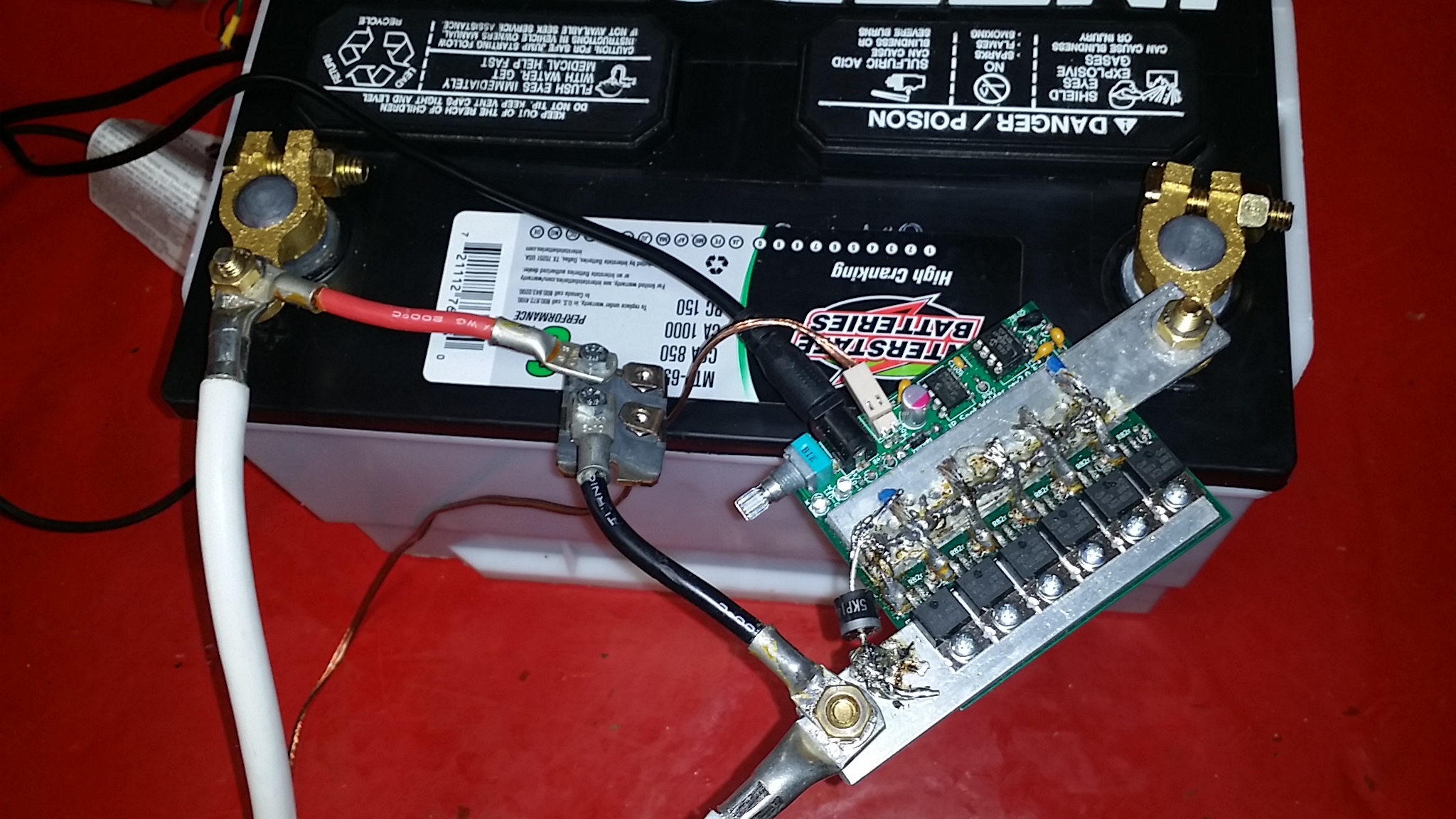
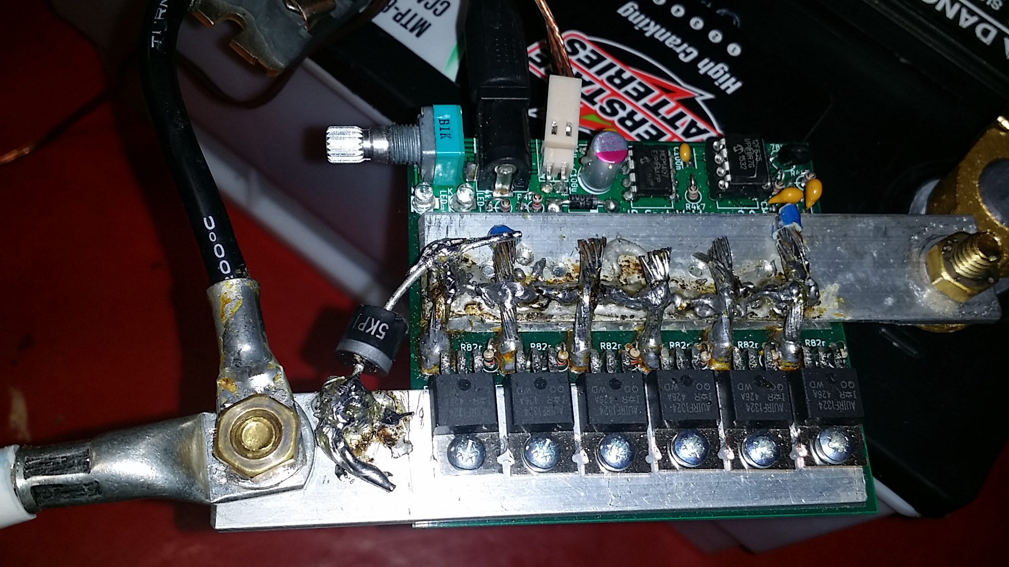
I got everything hooked up with the real long 6 foot 4AWG silicone wires. It seems to function normally so far. I did some quick test welds on .15 nickel and it welded it strong.
I added the TVS diode between the two aluminum plates. I kept the huge schoty diode I always used between the positive and negative terminals.
These 6 foot extremely flexible cables will make welding on my extremely large battery pack a breeze. It was really annoying using the stiff short cables the welder came with.
If you're going to go with long cables, might as well go with real long cables.
tomjasz said:Would it be possible to describe what diode and photo of how it’s installed?
I don’t understand the purpose other than on a superficial level, but have learned to solder very well and can follow the leader.
Thanks,
The post above by Offroader shows it well. There are two diodes. One big schottky diode goes across the leads as close to the welder as possible. Another TVS diode goes across the FET legs to catch what the other diode misses. The leads, especially long ones, will act like an inductor and store energy during the pulse. When the pulse ends, that energy has to go somewhere. Without the diode, the voltage all goes to the FETs, which could possibly damage them.
Lots of people run these circuits without the diode and it doesn't blow up as long as the supply voltage, current and lead inductance stay within reason. I'm only using a diode across the leads and no TVS diode.
Keeping the two welding wires close together (zip ties or tape) will minimize the inductance. The idea is to minimize the loop area.
Just for fun, I fired my welder into a small copper coil made from 12ga wire. This could work well as a coil gun driver. My coil spread itself out when I fired it and the nail sitting next to it did take off pretty good. A coil like this will have way more inductance than typical welding leads.
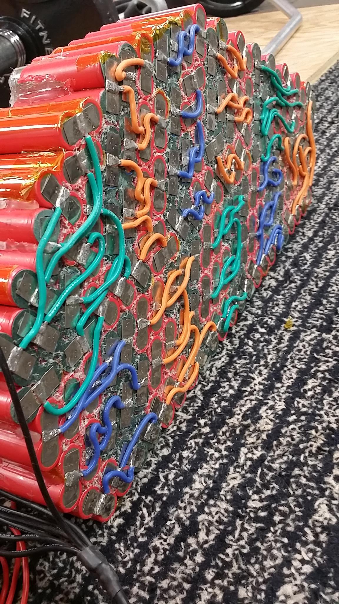
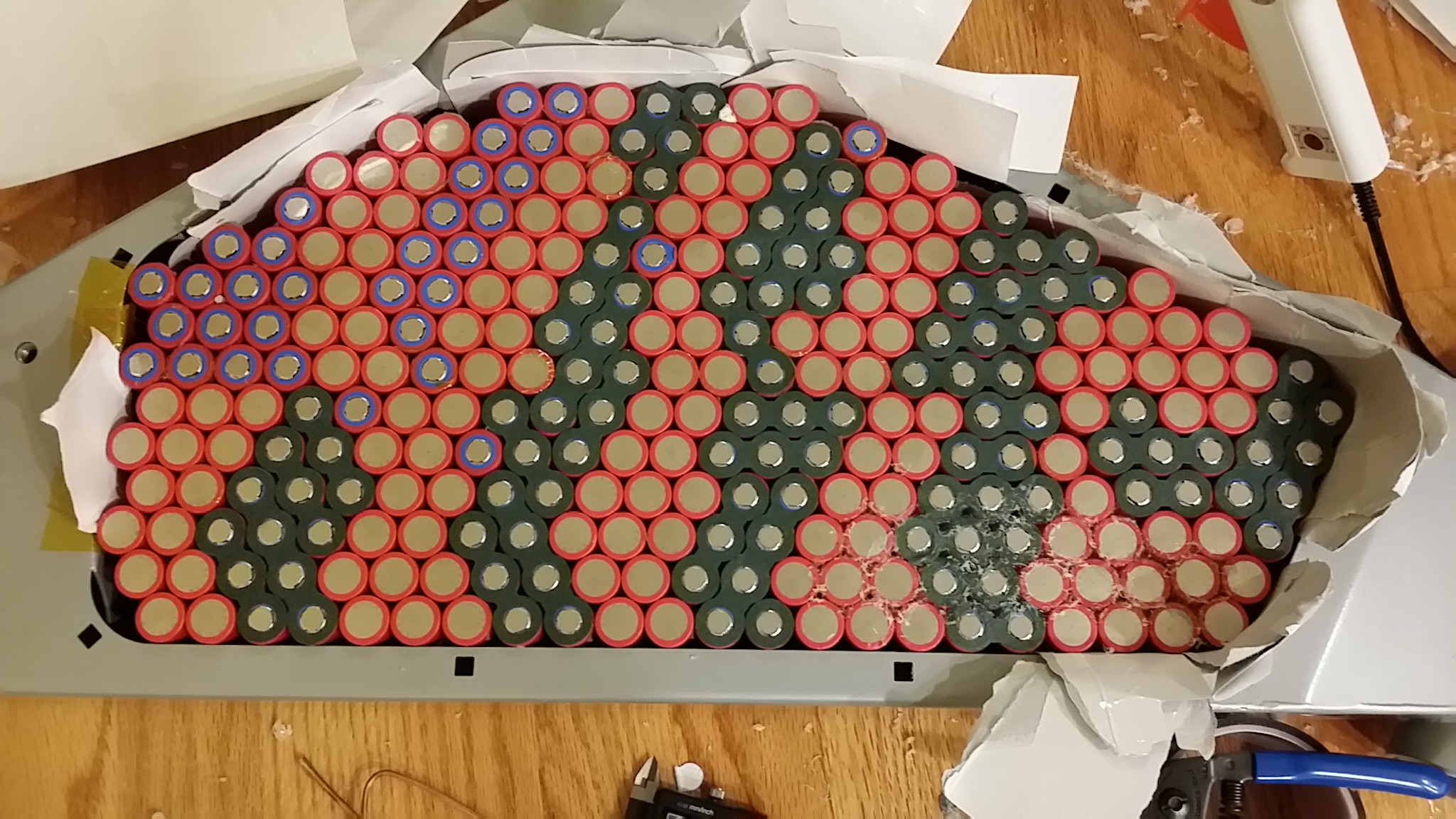
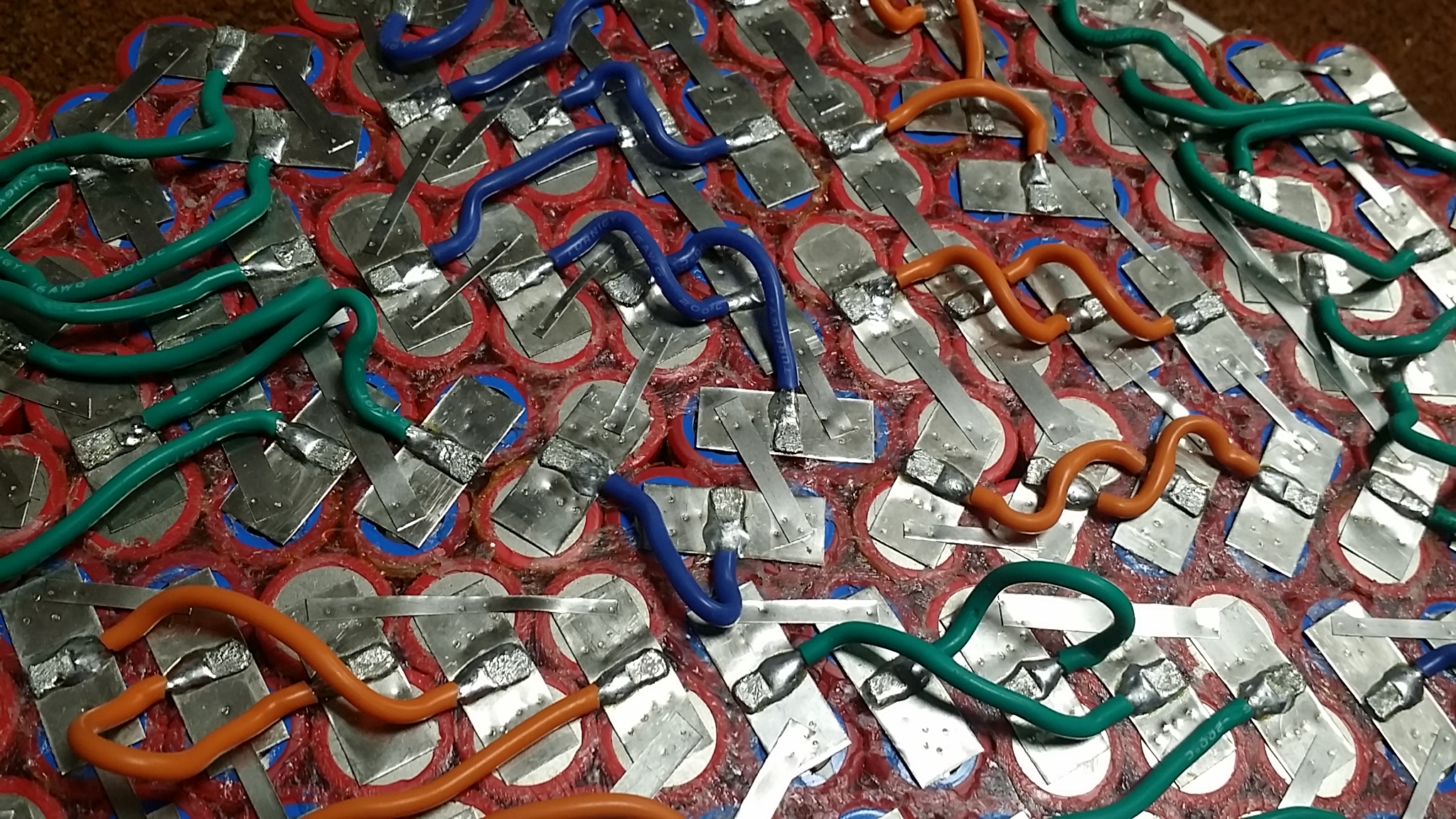
Here it is, the most complex 280 cell 20s ebike battery built, but still doesn't have any of the cells in parallel. This pack was built with perfect current distribution in mind so all cells would have exactly the same load in a rounded pack.
Its been maybe 3 years and the cells are still all perfectly balanced.
Mostly all cells were extremly clsoe to 3.270 volts, I found 4 cells that were slightly out by .02 volts.
There were two cells that were 3.29 volts, and one of those cells was accidentally over charged to 4.3 or 4.4 volts when I forgot to weld the nickel tab down. Since the two cells are in parallel I have no idea which of the two is causing trouble. I'm also not sure if I balanced them correctly after the over charge but I believe I did.
There were two other cells that were 3.256. Not sure if they were always low.
So who really needs a BMS anyway when after 3 years the cells are all still perfectly balanced? Even though it seems like a waste I'm going to parallel the cells and put in the MAX-E BMS that has been sitting unused. I plan on using this battery to commute to work so will be using the bike a lot more.
The big question is would this pack have worked just as well if I used nickel tab through out and no wires? To be honest, probably . Most likely it was a big waste of time. I would need to know how other packs that were welded and were rounded like this, and had no BMS or cells in parallel, stayed balanced. Even though the resistance might be a little different on some outlying cells if using nickel tab throughout it is so small to not make any difference in cell degradation and balancing.
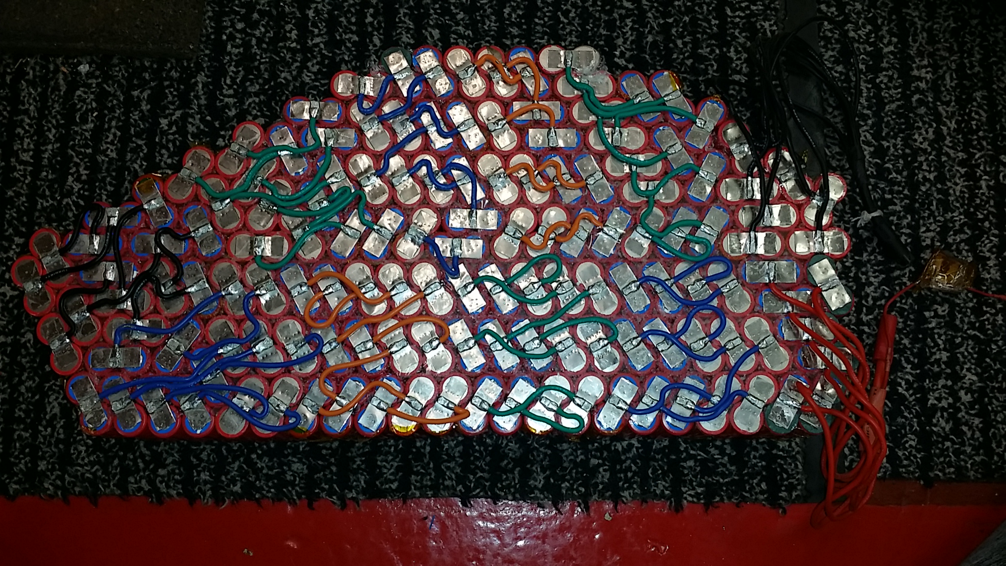
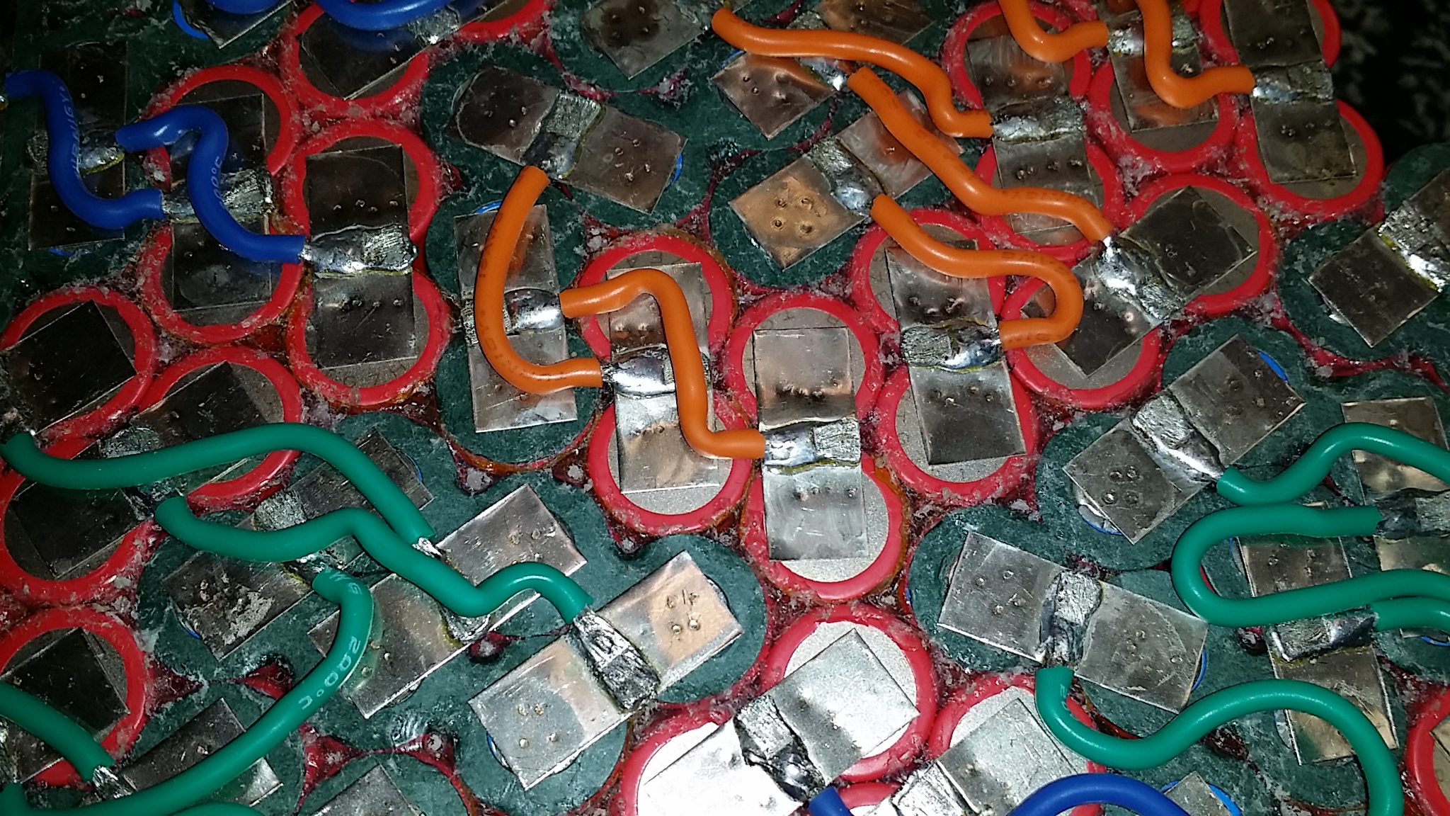
Each tab had wire carefully soldered and then welded. The 16 awg wire also allows a lot more current then nickel tab.
Two cells are in parallel, but the other side may or may not have those same two cells in parallel, so most cells are not in parallel, but there are a few 2 cell paralleled cells that happened by chance to have the nickel tabs on the same 2 cells on both sides of the pack.
Its been maybe 3 years and the cells are still all perfectly balanced.
Mostly all cells were extremly clsoe to 3.270 volts, I found 4 cells that were slightly out by .02 volts.
There were two cells that were 3.29 volts, and one of those cells was accidentally over charged to 4.3 or 4.4 volts when I forgot to weld the nickel tab down. Since the two cells are in parallel I have no idea which of the two is causing trouble. I'm also not sure if I balanced them correctly after the over charge but I believe I did.
There were two other cells that were 3.256. Not sure if they were always low.
So who really needs a BMS anyway when after 3 years the cells are all still perfectly balanced? Even though it seems like a waste I'm going to parallel the cells and put in the MAX-E BMS that has been sitting unused. I plan on using this battery to commute to work so will be using the bike a lot more.
The big question is would this pack have worked just as well if I used nickel tab through out and no wires? To be honest, probably
. Most likely it was a big waste of time. I would need to know how other packs that were welded and were rounded like this, and had no BMS or cells in parallel, stayed balanced. Even though the resistance might be a little different on some outlying cells if using nickel tab throughout it is so small to not make any difference in cell degradation and balancing.
Each tab had wire carefully soldered and then welded. The 16 awg wire also allows a lot more current then nickel tab.
Two cells are in parallel, but the other side may or may not have those same two cells in parallel, so most cells are not in parallel, but there are a few 2 cell paralleled cells that happened by chance to have the nickel tabs on the same 2 cells on both sides of the pack.
litespeed
100 kW
That is super complex. I like the not complex version I have been following for Years compliments of madin88.
While I would be quite arrogant in saying “I’m excellent at soldering” I would be scared of that many connections in fear of a cold solder joint. I betcha you would need some really serious equipment to find a difference in current capabilities between that pack and a properly all nickel pack like what I built. 20s15p 30Q. I guess I need to set up video to show how minimal voltage drop is at 200 amps but it’s not much.
Different strokes for different folks.
Tom
Attachments
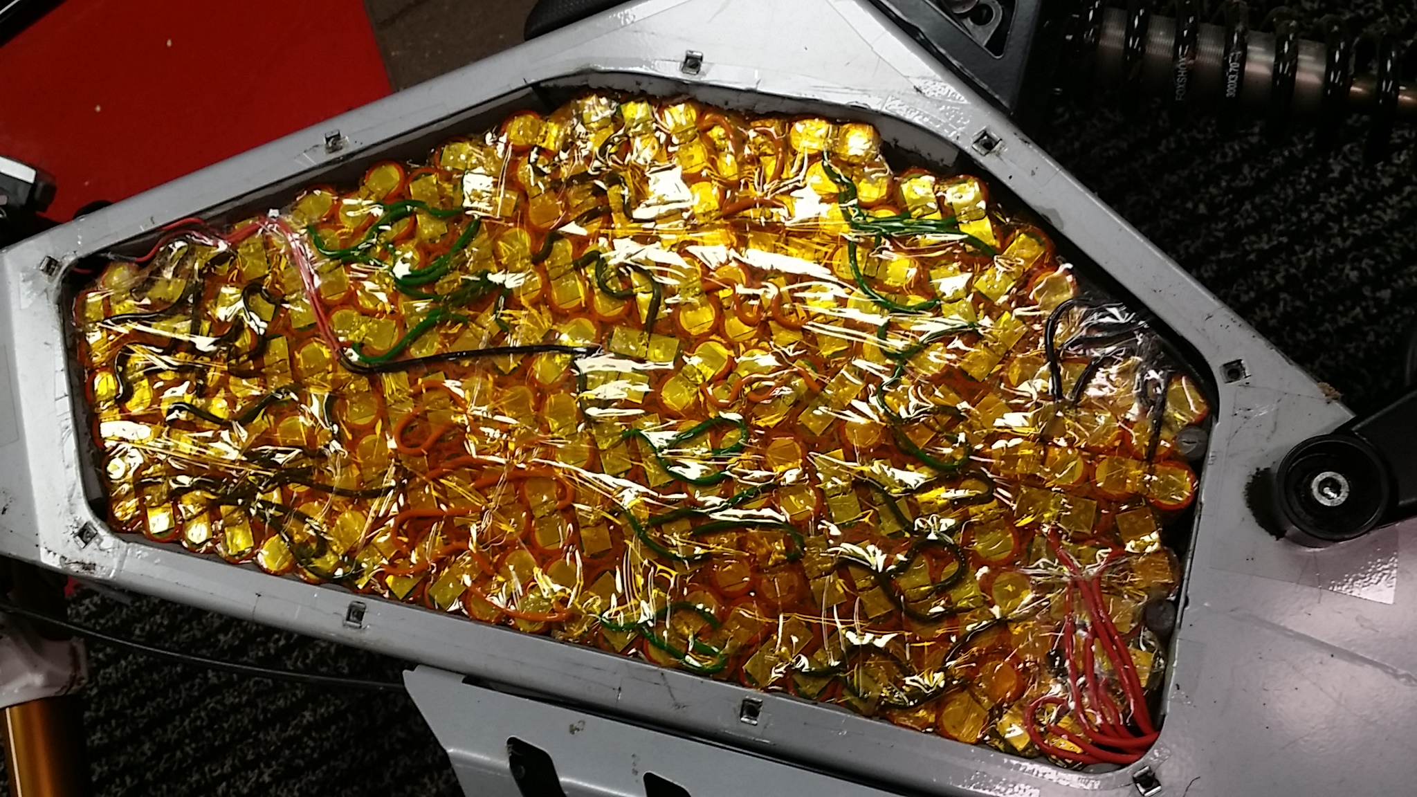
My pack was built to max out the battery size in my frame so I had to actually squeeze it together or compress it inside the frame and then glued together compressed like that.
Since my pack was rounded and not square it would have been difficult to get the current to flow evenly through the pack, especially around the edges, that is why I used the wires. At that time there was a lot of discussion about equal current draw through the cells. I really don't know if it matters or not or if anyone even tested anything.
The soldering had to be done carefully and closely watched to make sure it was done properly, not something I would recommend to the impatient or inexperienced. The good part was that the wires were soldered off the battery so I was able to really heat everything up for a long time without worry about overheating the cells. Then after the wires were soldered to the nickel they why welded onto the battery.
litespeed
100 kW
And what a great job you did! Very impressive job.
Tom
Tom
Thanks, I still kind of believe it was worth the work because its hard to imagine having a few cells out of the direct flow of electricity not causing issues with longevity if pushing the cells close to max.
I just wanted to comment on my new 4AWG silicone flexible wire. This new wire was so worth it. Welding is so much easier. The wires may be longer than necessary, but just being able to have the wires fall to both sides of the pack in the best position makes the probes feel really light and like you don't even have wires on them.
It is as if you are just holding two pencils in your hand and you can put them down right besides the pack. T
Each nickel strip has to be welded and then the probes put down to line up the next piece. The flexible wire allows for very good precision when using the probes.
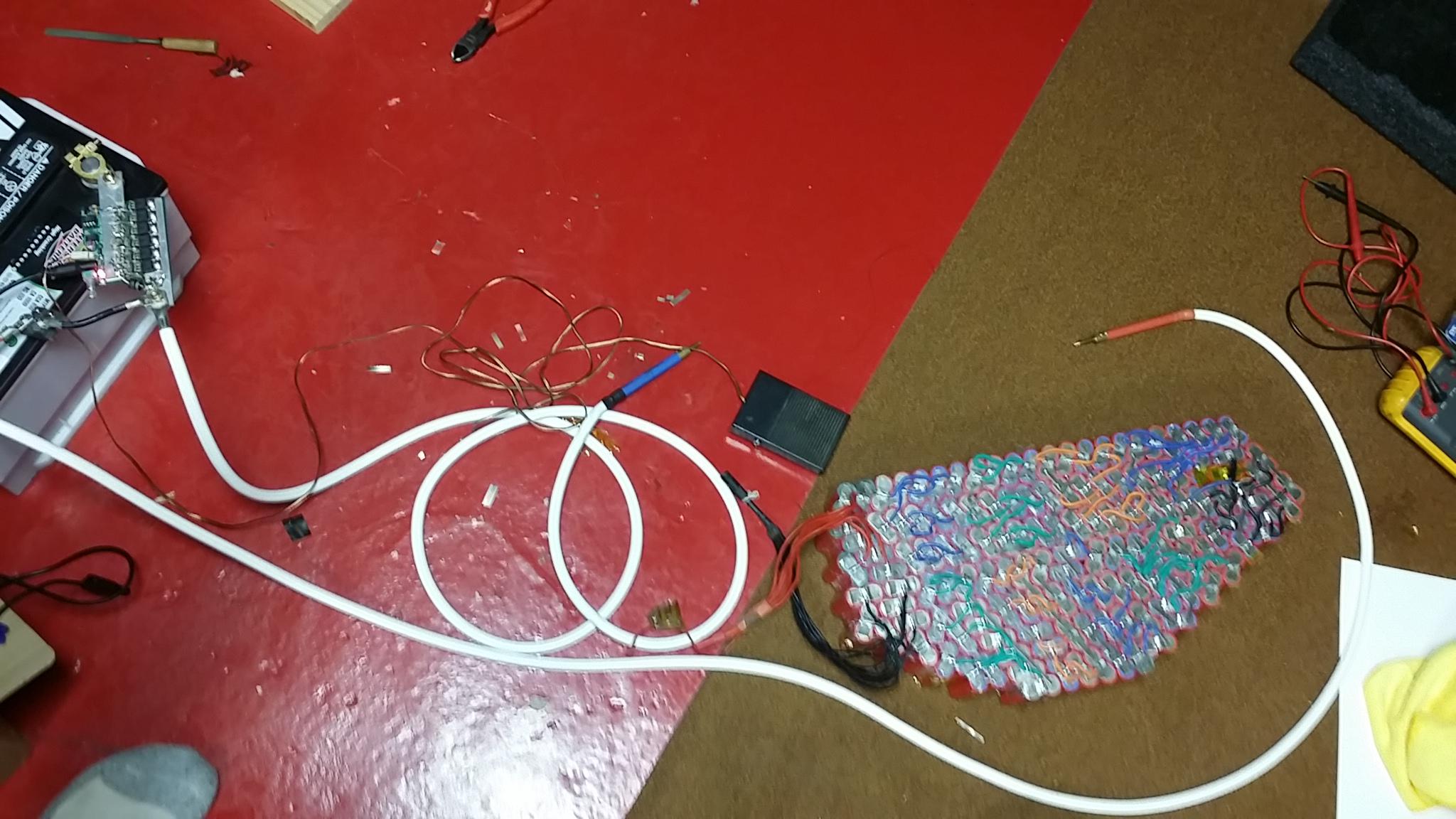
Each tiny nickel strip needs to be added to put all 280 cells in parallel.
I just wanted to comment on my new 4AWG silicone flexible wire. This new wire was so worth it. Welding is so much easier. The wires may be longer than necessary, but just being able to have the wires fall to both sides of the pack in the best position makes the probes feel really light and like you don't even have wires on them.
It is as if you are just holding two pencils in your hand and you can put them down right besides the pack. T
Each nickel strip has to be welded and then the probes put down to line up the next piece. The flexible wire allows for very good precision when using the probes.
Each tiny nickel strip needs to be added to put all 280 cells in parallel.
Do you have any idea if the cells in the center of the pack are going to get a lot hotter than the ones around the edge?
The temp probe that I have in the center of the pack gets to as high as 50C sometimes. I wouldn't know but considering the pack has foam around the edges and is well insulated it probably stays about the same temperature as the heat probably gets distributed between the whole pack which is hot glued tightly together pretty quickly.
I would also say that it hasn't caused any balance issues either as the pack is still perfectly balanced so it would make me think its not causing any cells to act differently which would change the voltage even a small amount.
I would also say that it hasn't caused any balance issues either as the pack is still perfectly balanced so it would make me think its not causing any cells to act differently which would change the voltage even a small amount.
"48v is too much. 12v is about the maximum.
Consider that on mine, I measured about 3,000A during the pulse at 12v. There has been some success using gigantic capacitors and a 12v supply. The average power is not that much so the caps can get recharged with a reasonably small 12v supply."
Fletcher,
How did you measure the current of such a short pulse?
Is there a special device that does that or you rigged something up using standard testing equipment?
I want to test mine.
Thanks!
fechter said:48v is too much. 12v is about the maximum.
Consider that on mine, I measured about 3,000A during the pulse at 12v. There has been some success using gigantic capacitors and a 12v supply. The average power is not that much so the caps can get recharged with a reasonably small 12v supply.
Fletcher,
How did you measure the current of such a short pulse?
Is there a special device that does that or you rigged something up using "standard" testing equipment?
I want to test mine.
Thanks!
Similar threads
- Replies
- 8
- Views
- 501
- Replies
- 2
- Views
- 173
- Replies
- 3
- Views
- 1,317
- Replies
- 18
- Views
- 1,846
- Replies
- 23
- Views
- 2,184