
You are using an out of date browser. It may not display this or other websites correctly.
You should upgrade or use an alternative browser.
You should upgrade or use an alternative browser.
APL's DIY axial-flux motor
- Thread starter APL
- Start date
APL
100 kW
- Joined
- Aug 6, 2018
- Messages
- 1,113
Finally finished all the set screw holes, the 3mm grubs are just the right size, and I feel confident that things are
strong enough. I'll drill down into the lamination stack a millimeter or so, and that will lock everything in place.
I put an old core slug in it for show, but the new ones will be a little different size.
A little hard to see.

Took a photo of some 5mm phase wires,.. 15mm of wires should cary some juice! And theres plenty of room for more
holes for sensors and a thermal if need be. Thanks for your help amberwolf, that worked out nice.")
View attachment 1
The weight as it sets is 1530 grams, or about 3.5 lbs, and the torque arms and bolts are another 150g's.
The next move would be the lamination stacks, but I've been holding off on that, because things keep changing,
and I want to be absolutely sure of the size. Plus, I'm not happy with putting heat to them with the plasma torch,
and I'm holding out for a horizontal band saw, which I think will be the ticket. Craigslist is not being cooperative
at the moment, and I'm to cheap to just go out and buy a new one. Retired,.. fixed income.
Pole magnets came today, and they look good for being so cheap,.. defiantly got 'the power'. Bonding them up is way
down the road, but I'm going to have to be careful because they are real thin, and one mistake will snap them in half.
Looking at the slots, I have a lot of space between the poles, and some aluminum in between that might have to be
milled down a few millimeters to get away from induction, but at 300 rpm, I don't expect it to be a problem, so I'm
just going to leave it for now, and if heat becomes an issue, I'll go back and deal with it.
That kind of induction needs to be in super close proximity anyway, like a few thousands of an inch.
Most of these motors have 'pie' shaped stator and pole magnets, which I might have to go to, down the road, but I'm
interested in seeing how this is going to work for the moment. Probably going to need to pedal a bit to get it started,
but I can do that. First,.. get it to work,.. then, do the tweaks.
I'm finally making some headway on the 'stator tooth vs pole number' thing. To bad I switched from 24 to 21 teeth,
24 tooth axial stators are common, and usually have 8 or 16 poles, so they are sort of a no brainer.
21 is a rare combo, but it can be done, (knock on wood).
The tech and math and all the information on this stuff is immensely complicated, and would take years of schooling
to understand, my hat goes off to anyone that has any kind of grip on any of that world. Good gads!
Gives me a major headache, and glasses my eyes over, but thats what Ibuprofen is for.
Anyway, still working on it, and found this chart, and web site,.. PDF, so get some coffee while it's downloading...
(actually, it's only a few pages).

You can see that 21 poles have an option of 14, 16, 20, 22, 26, and 28 poles,.. if I'm understanding it right.
Theres more to it than that, of course, magnet width and spacing, and overlap,.. but I have hope.
In for a penny,.. in for a pound.
Site:http://citeseerx.ist.psu.edu/viewdoc/download?doi=10.1.1.508.1648&rep=rep1&type=pdf
strong enough. I'll drill down into the lamination stack a millimeter or so, and that will lock everything in place.
I put an old core slug in it for show, but the new ones will be a little different size.
A little hard to see.
Took a photo of some 5mm phase wires,.. 15mm of wires should cary some juice! And theres plenty of room for more
holes for sensors and a thermal if need be. Thanks for your help amberwolf, that worked out nice.
View attachment 1
The weight as it sets is 1530 grams, or about 3.5 lbs, and the torque arms and bolts are another 150g's.
The next move would be the lamination stacks, but I've been holding off on that, because things keep changing,
and I want to be absolutely sure of the size. Plus, I'm not happy with putting heat to them with the plasma torch,
and I'm holding out for a horizontal band saw, which I think will be the ticket. Craigslist is not being cooperative
at the moment, and I'm to cheap to just go out and buy a new one. Retired,.. fixed income.
Pole magnets came today, and they look good for being so cheap,.. defiantly got 'the power'. Bonding them up is way
down the road, but I'm going to have to be careful because they are real thin, and one mistake will snap them in half.
Looking at the slots, I have a lot of space between the poles, and some aluminum in between that might have to be
milled down a few millimeters to get away from induction, but at 300 rpm, I don't expect it to be a problem, so I'm
just going to leave it for now, and if heat becomes an issue, I'll go back and deal with it.
That kind of induction needs to be in super close proximity anyway, like a few thousands of an inch.
Most of these motors have 'pie' shaped stator and pole magnets, which I might have to go to, down the road, but I'm
interested in seeing how this is going to work for the moment. Probably going to need to pedal a bit to get it started,
but I can do that. First,.. get it to work,.. then, do the tweaks.
I'm finally making some headway on the 'stator tooth vs pole number' thing. To bad I switched from 24 to 21 teeth,
24 tooth axial stators are common, and usually have 8 or 16 poles, so they are sort of a no brainer.
21 is a rare combo, but it can be done, (knock on wood).
The tech and math and all the information on this stuff is immensely complicated, and would take years of schooling
to understand, my hat goes off to anyone that has any kind of grip on any of that world. Good gads!
Gives me a major headache, and glasses my eyes over, but thats what Ibuprofen is for.
Anyway, still working on it, and found this chart, and web site,.. PDF, so get some coffee while it's downloading...
(actually, it's only a few pages).
You can see that 21 poles have an option of 14, 16, 20, 22, 26, and 28 poles,.. if I'm understanding it right.
Theres more to it than that, of course, magnet width and spacing, and overlap,.. but I have hope.
In for a penny,.. in for a pound.
Site:http://citeseerx.ist.psu.edu/viewdoc/download?doi=10.1.1.508.1648&rep=rep1&type=pdf
APL
100 kW
- Joined
- Aug 6, 2018
- Messages
- 1,113
Doing some more searching, and found some info. on 21 slot stators, saying that it's not recommended using 20, or 21
poles, with that many teeth. Then, another chart of LCM numbers showing that 26 poles are better than 28, stating
that a higher LCM number is better. So at the moment, I'm going to go for 26 pole magnets, unless I can find some
more info. that changes that.

Info. site: https://www.researchgate.net/profile/J_Pyrhoenen/publication/4289947_Guidelines_for_Designing_Concentrated_Winding_Fractional_Slot_Permanent_Magnet_Machines/links/56a0d2ff08aee4d26ad8a4d8/Guidelines-for-Designing-Concentrated-Winding-Fractional-Slot-Permanent-Magnet-Machines.pdf?origin=publication_list
I'm going to have to do a midway design change, and move the back iron rings from outside, to the inside of the rotors,
in order to get that many magnets on them. Which is something I was thinking about doing anyway,.. and allows for any
number of pole combinations, plus gets away from slotting the rotors.
The motor will be slightly wider, but easier to experiment with.
Found a band saw at long last, and have been busy slicing up laminations. Works quite well, and although it's still going to
be a lot of cutting, at least I can be doing something else. Lamination material will be cut into 35mm stacks, and then into
10mm stacks, 40mm high. I'm not sure how long a blade will last, but so far it's doing pretty good.

I plan to bond the 40mm stacks together with some kind of glue, that needs to be real thin, like crazy glue, but with a
10 - 15 minute working time,.. any ideas?
Ordered out the rotor, and bearing cap aluminum, so thats on it's way.
I should start thinking about the back iron rings,and what they are going to be made from,.. probably some regular soft
steel, about an 1/8" thick or so. I'll have to look into that a little bit.
While I was looking around on Youtube, I ran across a video on aluminum anodizing colors. Something I've always
wanted to try. I was surprised to see how simple it appears to be, and thought that this motor would be a good
thing to try it out on. We all know that things that look cool work better,...right? 8)
poles, with that many teeth. Then, another chart of LCM numbers showing that 26 poles are better than 28, stating
that a higher LCM number is better. So at the moment, I'm going to go for 26 pole magnets, unless I can find some
more info. that changes that.
Info. site: https://www.researchgate.net/profile/J_Pyrhoenen/publication/4289947_Guidelines_for_Designing_Concentrated_Winding_Fractional_Slot_Permanent_Magnet_Machines/links/56a0d2ff08aee4d26ad8a4d8/Guidelines-for-Designing-Concentrated-Winding-Fractional-Slot-Permanent-Magnet-Machines.pdf?origin=publication_list
I'm going to have to do a midway design change, and move the back iron rings from outside, to the inside of the rotors,
in order to get that many magnets on them. Which is something I was thinking about doing anyway,.. and allows for any
number of pole combinations, plus gets away from slotting the rotors.
The motor will be slightly wider, but easier to experiment with.
Found a band saw at long last, and have been busy slicing up laminations. Works quite well, and although it's still going to
be a lot of cutting, at least I can be doing something else. Lamination material will be cut into 35mm stacks, and then into
10mm stacks, 40mm high. I'm not sure how long a blade will last, but so far it's doing pretty good.
I plan to bond the 40mm stacks together with some kind of glue, that needs to be real thin, like crazy glue, but with a
10 - 15 minute working time,.. any ideas?
Ordered out the rotor, and bearing cap aluminum, so thats on it's way.
I should start thinking about the back iron rings,and what they are going to be made from,.. probably some regular soft
steel, about an 1/8" thick or so. I'll have to look into that a little bit.
While I was looking around on Youtube, I ran across a video on aluminum anodizing colors. Something I've always
wanted to try. I was surprised to see how simple it appears to be, and thought that this motor would be a good
thing to try it out on. We all know that things that look cool work better,...right? 8)
Back iron in most hubmotors is probably simple steel pipe (and thus why most of the DD hubmotors are one of a very few diameters, and tend to have the same thickness of backiron, whether they need that thickness or something different). I haven't verified that the actual diameter of the backiron corresponds to steel pipe sizes, though.
I suspect this creates a design constraint upon most of the hubmotor makers that they work within to create their motors, and that there might be more "optimal" designs made for various purposes if there were pipe diameters commonly available that made them possible.
I suspect this creates a design constraint upon most of the hubmotor makers that they work within to create their motors, and that there might be more "optimal" designs made for various purposes if there were pipe diameters commonly available that made them possible.
wturber
1 MW
APL said:I plan to bond the 40mm stacks together with some kind of glue, that needs to be real thin, like crazy glue, but with a
10 - 15 minute working time,.. any ideas?
Maybe a low viscosity epoxy for fiberglass laminating from West Systems or Aeropoxy? Use it in a moderately warm environment for less viscosity (and faster curing). Use clamping to squeeze out any excess.
APL said:While I was looking around on Youtube, I ran across a video on aluminum anodizing colors. Something I've always
wanted to try. I was surprised to see how simple it appears to be, and thought that this motor would be a good
thing to try it out on. We all know that things that look cool work better,...right? 8)
Of course. My car runs better once washed and waxed, and my bike fenders block splashes much better since I painted them yellow and added a clear coat finish. Doesn't hurt to wax them now and then either. :^)
APL
100 kW
- Joined
- Aug 6, 2018
- Messages
- 1,113
Being a lowly shop rat, I know a little about everything, and a lot about nothing,..and usually have to rely on logic,
intuition, and a good gut feeling. although logic works the best.
Most all of motor design is math and equations,.. which my little pea brain doesn't accept.
After looking around this morning, and getting my usual headache, I didn't find the secret to back iron yet, but started
looking at other motors, and what they use.
I also took a look at the Bionx motors I have, and came to the conclusion that it depends on the power you plan to put
in to it. (current)
If the parts of the motor that make up the flux path are thought of as resistors, then you have a chain of resistors,
the smallest one being the weakest link in the chain. They all need to be the same size.
The size is determined by how much current is going to be used.
The little 250 watt Bronx has a really thin back iron ring, and single strand wire. The 500+ watt motor has a lot thicker
back iron ring and multi strand wire, and the 1000 watt Crystalyte has even more.


Anyway,.. hope I'm not being confusing, but if I want to put 750 watts into this motor, I'm probably going to have to have
fairly thick back iron,.. at least 5mm, or 3/16", along with the core, and wiring, and everything else.
There goes my light weight design... Hope I'm not 'too' far off on this, amberwolf, let me know what you think,
you know a lot more about this stuff than I do.
Thanks wtuber, for the fiberglass epoxy idea, that sounds like it will work, and give me enough time to get things laid
up, in position, and clamped. I'll look into it,..I wonder what the bonding strength is,.. although I probably don't need
that much. Going to be a royal mess though!
intuition, and a good gut feeling. although logic works the best.
Most all of motor design is math and equations,.. which my little pea brain doesn't accept.
After looking around this morning, and getting my usual headache, I didn't find the secret to back iron yet, but started
looking at other motors, and what they use.
I also took a look at the Bionx motors I have, and came to the conclusion that it depends on the power you plan to put
in to it. (current)
If the parts of the motor that make up the flux path are thought of as resistors, then you have a chain of resistors,
the smallest one being the weakest link in the chain. They all need to be the same size.
The size is determined by how much current is going to be used.
The little 250 watt Bronx has a really thin back iron ring, and single strand wire. The 500+ watt motor has a lot thicker
back iron ring and multi strand wire, and the 1000 watt Crystalyte has even more.
Anyway,.. hope I'm not being confusing, but if I want to put 750 watts into this motor, I'm probably going to have to have
fairly thick back iron,.. at least 5mm, or 3/16", along with the core, and wiring, and everything else.
There goes my light weight design...
Hope I'm not 'too' far off on this, amberwolf, let me know what you think,you know a lot more about this stuff than I do.
Thanks wtuber, for the fiberglass epoxy idea, that sounds like it will work, and give me enough time to get things laid
up, in position, and clamped. I'll look into it,..I wonder what the bonding strength is,.. although I probably don't need
that much. Going to be a royal mess though!
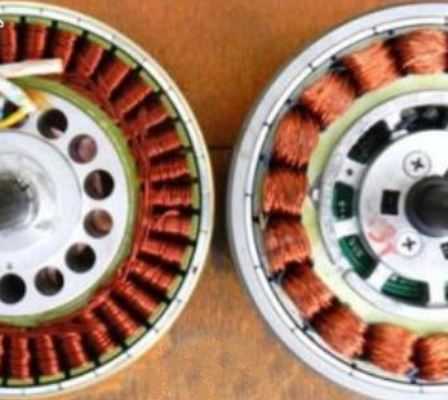
Its my understanding that the thickness of the back iron is a ratio to the width of the magnet. Meaning that for a given diameter of motor, having a few large magnets is less expensive, but requires thicker back iron.
The same diameter of motor can be made with a higher number of magnets that are smaller, but doing that is more expensive. The major benefit being that there is a significant reduction in the weight of back-iron (and some reduced cogging?).
Pic below is a MAC vs BPM
The same diameter of motor can be made with a higher number of magnets that are smaller, but doing that is more expensive. The major benefit being that there is a significant reduction in the weight of back-iron (and some reduced cogging?).
Pic below is a MAC vs BPM
APL
100 kW
- Joined
- Aug 6, 2018
- Messages
- 1,113
Interesting, spinning magnets, I hadn't thought of it like that. Although I read some information that collaborates that
in a few different papers this morning.
I would think that more, smaller magnets, would be for smoothness,(less cogging), like you said. The weight of more
tooth and windings are probably close to the extra back iron weight of the other motor? Certainly harder to wind.
Hmm.., the mystery continues. More poles makes for a slower motor, so maybe rpm has something to do with it.
Dang, that MAC has thin back iron!
I have more research to do yet,.. in my searches I've been calling it 'back iron', but I just discovered that it's also called
a yoke, or 'back yoke'. Kinda like calling a bike stem a gooseneck? Anyway, now I have to see what that turns up.
In the end, I suppose logically, I should lean towards heavy, or thicker, rather than thinner. So what if the motor weighs
more at this point, it's an experimental, and the rotors can probably use some flywheel weight anyway.
I would suspect that being to thin, is worse than being to thick, as far as function goes.
APL
100 kW
- Joined
- Aug 6, 2018
- Messages
- 1,113
Also, I suppose it's worth mentioning at this point, that the end windings on the side of the motor, do not contribute
to thrust. The windings that goes 'across' the core, or through the motor, are most important. So a long, thin tooth is
more efficient than a fat, or square tooth. Which might be another reason for many teeth, instead of fewer teeth?
Just thinking out loud. I have so much to learn about this stuff, it ain't even funny...
APL
100 kW
- Joined
- Aug 6, 2018
- Messages
- 1,113
Making a little headway on laminations. They have been cut into rough piles, and then put on the mill, to make
them all the same length,..35mm, a little wider than the OD. width of the stator plates. That gives me some wiggle
room, and moves the PM magnets a little farther out from the aluminum.
You got to love the mill, it makes all things equal.

So far, roughly 5 lbs of steel, I hope to reduce that a bit.

Finally starting to see some core pieces! A bucket full of .013" laminations.
These will be placed into stacks 40mm high, and then cleaned up on the mill to 10mm thick. I'll probably mill the middle
of the sides a little, to narrow the windings, so that more air can pass by, for cooling,.. and reduce the weight.
The saw blade is holding up surprisingly well, and I think one blade is going to do all the cutting. The end mills don't
like this stuff very much, and I've lost one already. I probably should have bought some cheap sacrificial end mills before
I ever got started.
them all the same length,..35mm, a little wider than the OD. width of the stator plates. That gives me some wiggle
room, and moves the PM magnets a little farther out from the aluminum.
You got to love the mill, it makes all things equal.
So far, roughly 5 lbs of steel, I hope to reduce that a bit.
Finally starting to see some core pieces! A bucket full of .013" laminations.
These will be placed into stacks 40mm high, and then cleaned up on the mill to 10mm thick. I'll probably mill the middle
of the sides a little, to narrow the windings, so that more air can pass by, for cooling,.. and reduce the weight.
The saw blade is holding up surprisingly well, and I think one blade is going to do all the cutting. The end mills don't
like this stuff very much, and I've lost one already. I probably should have bought some cheap sacrificial end mills before
I ever got started.
spinningmagnets said:Its my understanding that the thickness of the back iron is a ratio to the width of the magnet. Meaning that for a given diameter of motor, having a few large magnets is less expensive, but requires thicker back iron.
The same diameter of motor can be made with a higher number of magnets that are smaller, but doing that is more expensive. The major benefit being that there is a significant reduction in the weight of back-iron (and some reduced cogging?).
Right, the thickness of the back iron should be about 1/3 of the width of the magnets to avoid saturation (flux leakage).
Aside from the weight reduction of the rotor, a higher pole count design will lead to a lower phase-to phase resistance making the motor more efficient to produce torque. The downside of a high pole design are the high ERPM, or with other words the iron losses will be higher.
APL
100 kW
- Joined
- Aug 6, 2018
- Messages
- 1,113
Thank you madin88, for that general rule for back iron thickness. Thats just what I'm looking for. Since this
isn't exactly a precision motor, things don't need to be all that perfect yet.
10mm wide PM's, 3.3mm back iron, 1/8" steel. Wonderful!
That brings me to something thats been bothering me as of late, the PM magnet overlap vs tooth width.
I didn't notice it at first, but now I see it as a big power loss that I might still be able to recoup.
The PM magnet needs to be somewhat wider than the stator tooth.

Might there be another general measurement for that?
(Although, admittedly, I don't have a lot of choices for magnet sizes on this design)
Stator tooth profiles can be changed, and good to know for next gen. projects.
isn't exactly a precision motor, things don't need to be all that perfect yet.
10mm wide PM's, 3.3mm back iron, 1/8" steel. Wonderful!
That brings me to something thats been bothering me as of late, the PM magnet overlap vs tooth width.
I didn't notice it at first, but now I see it as a big power loss that I might still be able to recoup.
The PM magnet needs to be somewhat wider than the stator tooth.
Might there be another general measurement for that?
(Although, admittedly, I don't have a lot of choices for magnet sizes on this design)
Stator tooth profiles can be changed, and good to know for next gen. projects.
I havn't yet read everything I should between page one and last of this thread, trying to squeeze this visit into a very short break. Back in the beginning, you were mixing up some epoxy and powder that you first called ferrite then iron. So I don't know exactly what you mixed...
Now when I do this, I use JBWeld, cause its already got 5% ferrosilicon according to the MSDS sheet. Seems to come from the dark half of the mix. Strong magnet will stick to it, just barely. My tests show good Q out past 1MHz for flybacks, not saying anything for motors. Starting there, I load it up with even more powder.
This is where it gets tricky. Cause crushed ferrite doesn't carry much flux before it saturates, may be useless for motors. Soft manganese oxide loses low-loss properites once iron oxide gets involved and starts to form hard domains. So you have to be careful to work in manganese's flux range, and keep iron oxide in annealed state. Never saturate, and no using neodymium to pick up powder. Unfixable after bound in epoxy that can't withstand iron's Curie temp.
I think you may be talking pure iron. Possibly hydrogen reduced? Which is good for flux, but not the best for blocking eddy currents. Might be better adding ferrosilicon, or carbonyl iron. The latter also reduced to nearly pure iron, but having residual onion structure for blocking eddy currents.
Attachments
APL said:Might there be another general measurement for that?
(Although, admittedly, I don't have a lot of choices for magnet sizes on this design)
Stator tooth profiles can be changed, and good to know for next gen. projects.
From what i know a general rule about the width of the magnets, or magnet coverage in % which would be the same thing, does not exist.
The coverage will influence the BEMF waveform and many other things..
I think you cannot do much wrong if you use magnets which have similar or a bit less width as the stator teeth.
APL
100 kW
- Joined
- Aug 6, 2018
- Messages
- 1,113
Thanks for the info. KD5ZXG, I didn't know that about JB Weld. I remember reading another one of your post's somewhere
else among these threads, along the same lines. Very interesting. The Ferrite core is not completely dead yet, and perhaps
it will be returned to in the future,.. it has to at least be better than coreless, I would think.
Or perhaps for a hybrid design, with laminated core, and ferrite ends, or pads on the stator tooth. People are clever, and
something may yet turn up.
One of the nice things about motors that are designed similar to this, is that these kind of things can be experimented
with, because all of the parts can be changed out and manipulated.
I spend a big part of every day thinking of an alternative to laminations, especially now, since thats the task at hand.
Even the lamination material itself is hard to get ahold of.
One of my latest thoughts was to use ferrofluid in a container for a core,.. but I'm sure that would turn out to be a bust
just as well. Danged eddy currents! Pesky little varmints. :wink:
APL
100 kW
- Joined
- Aug 6, 2018
- Messages
- 1,113
Thanks madin88, I'll start out with what I have,.. but I could make some more back iron rings later, and try some of the
13mm wide magnets. It would be an interesting comparison. (might have to anyway, if things go south)
I know theres a probably a lot of other things wrong with this motor.
Oh well, you got to start somewhere,..
13mm wide magnets. It would be an interesting comparison. (might have to anyway, if things go south)
I know theres a probably a lot of other things wrong with this motor.
Oh well, you got to start somewhere,..
markz
100 TW
What generic controller did you buy, the hksunwin?
I have mine open, and figured I'd eyeball the shunts, and solder in a parallel on the backside of the pcb, but I'd just use solid copper wire since I am beefing up the traces with it. Bad idea or should I match it more closely?
I have 3 shunts on my 1500W 48V hksunwin generic.
I have mine open, and figured I'd eyeball the shunts, and solder in a parallel on the backside of the pcb, but I'd just use solid copper wire since I am beefing up the traces with it. Bad idea or should I match it more closely?
I have 3 shunts on my 1500W 48V hksunwin generic.
amberwolf said:You could do a "shunt mod" to fool the controller into providing more current than it's designed for.
--adding more shunts in parallel with the existing one(s). This is both controllable, and undoable. Most of the shunt wires that are the same diameter and length are the same resistance, so if you already have two shunts, and add a third (out of a dead controller, for instance), you just added half-again the amount of current capability. (parallel resistance formulas). Add two shunts and you double the current handlign (halving the resistance). If the shunts aren't the same, it's not as easy to calculate, especially if you don't knwo what any of your shunt resistances are, but youc an experiment more easily (undoably easily, anyway) by adding / removing shunts than by adding/removing wire/solder from a shunt.
The generic "30A" controller on the left side of the SBC trike (taht runs an MXUS 4504) was turned into an 80A that way--it hasn't died yet.
I don't know what "brand" mine is; this is the thread for it:
https://endless-sphere.com/forums/viewtopic.php?f=2&t=68501
If you use solid copper wire, you are essentially short circuiting the shunts, and removing any current limiting, which will probably blow up the controller.
If you don't know what resistance the shunt you add is (I didn't) then you can't know what the resulting shunt resistance will be, and thus the new current limit. I "guessed" that since the shunts "looked" the same they'd be about teh same resistance, but they aren't. Adding a third shunt to mine should've just increased the amps by half-again, from 30 to 45, but instead it went from 30 ish to 80 ish.
If you put a shunt wire on the bottom of the PCB, it'll stick out so much it'll also probably short to the case.
APL
100 kW
- Joined
- Aug 6, 2018
- Messages
- 1,113
Lamination stacks are slowly coming along,.. defiantly labor intensive. Once I get three sets of seven, I can
bond them together, and clean them up on the belt sander, to open up the ends, and remove any burs,
or shorts.
I found a USA company that makes and sells lamination material,.. and can cut rolls of it down to 1/2". So
conceivably, one could buy a 16" roll, and just cut pieces to length, and stack them up.
Would have to have a wallet bigger than mine though.
http://tcmetal.com/toll-slitting/
Progress is going to be slow, until I can get all of these done. Otherwise, I ordered out the back iron steel,
rotor aluminum, and bearing caps, so all of that will be waiting to go.
Coming up will be bonding the magnets to the back iron rings, I'm sure thats going to be interesting, and I'll
have to devise a plan to keep those in place. I thought I saw some special glue for that somewhere on here.
There's a number of epoxies that are heat resistant, which is what you're after. If you look up some of DoctorBass's posts, there's an epoxy he recommends for gluing his "torque arms" on, and there are other posts by various people that used epoxies to glue magnets back on after they came off for one reason or another.
Copy/Paste propaganda from JB's website.
Q:How much heat can J-B Weld withstand?
A:Original J-B Weld can withstand a constant temperature of 500º F. The maximum temperature threshold is approximately 600º F for a short term (10 minutes). Refer to individual product packages for more temperature information.
I did once abuse a ground strap loaded with the stuff to emergency re-join two halves of an oilpan that otherwise wouldn't clear the frame of my car. That glue line leaked terribly, no matter how many times I redid it. JB proved fairly easy to scrape off with an ordinary propane torch, whatever temp that sort of flame might be. Eventually shoehorned a new replacement pan after unhooking everything necessary to raise the motor.
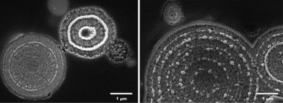
Surprisingly better for gluing up magnetics than oilpans. Here a racetrack core of JB loaded with crushed and partially annealed supressor ferrite (iron oxide, manganese oxide, zinc oxide). Homebrew Litz on Teflon plumbing tape. Wound two turns per cross. Less crowded at the crossings than a simple figure 8. Why bother? End to end capacitance, Check Q at 150KHz!
For the case of high flux, I wouldn't add filler. Keep it thin. Plain JB is only 3x more permeable than air/space/epoxy, even loaded with filler it presents a high reluctance gap you want to minimize. Uncured JB may also creep to envelop a strong magnet. I didn't mess with any permanent magnets, so it might be an issue. https://www.youtube.com/watch?v=Hi2hebnpHLw
Q:How much heat can J-B Weld withstand?
A:Original J-B Weld can withstand a constant temperature of 500º F. The maximum temperature threshold is approximately 600º F for a short term (10 minutes). Refer to individual product packages for more temperature information.
I did once abuse a ground strap loaded with the stuff to emergency re-join two halves of an oilpan that otherwise wouldn't clear the frame of my car. That glue line leaked terribly, no matter how many times I redid it. JB proved fairly easy to scrape off with an ordinary propane torch, whatever temp that sort of flame might be. Eventually shoehorned a new replacement pan after unhooking everything necessary to raise the motor.
Surprisingly better for gluing up magnetics than oilpans. Here a racetrack core of JB loaded with crushed and partially annealed supressor ferrite (iron oxide, manganese oxide, zinc oxide). Homebrew Litz on Teflon plumbing tape. Wound two turns per cross. Less crowded at the crossings than a simple figure 8. Why bother? End to end capacitance, Check Q at 150KHz!
For the case of high flux, I wouldn't add filler. Keep it thin. Plain JB is only 3x more permeable than air/space/epoxy, even loaded with filler it presents a high reluctance gap you want to minimize. Uncured JB may also creep to envelop a strong magnet. I didn't mess with any permanent magnets, so it might be an issue. https://www.youtube.com/watch?v=Hi2hebnpHLw
APL
100 kW
- Joined
- Aug 6, 2018
- Messages
- 1,113
Thanks for the awesome info KD5ZXG, I didn't know JB would hold up to 500 degrees. I love your core, especially the
home-brew Litz wire! She's a beauty! Your results are very impressive.
If I ever get this motor to spin, and yank me down the road, I'll have to return to the ferrite core, with all this new info.
I really wish I could find some silicon steel wire as well, I'm really intrigued by the idea of a 'Litz' core, (so to speak).
Working with thousands of little laminations has a very high 'suckage' factor!
Yea, I've read where using JB for Neo's is not the best idea, I'm still working on a good glue for that.
I'm not a magnetics/RF expert, but AFAIK the advantage of Litz wire is for very high frequencies, where the skin effect begins to dominate.
https://en.wikipedia.org/wiki/Litz_wire
Hubmotors are much lower frequencies (even for the PWM), so I don't know that the Litz wire will have any significant benefit (but it may affect the fill percentage you can achieve, which may reduce the amount of current (torque) the motor handles.
https://en.wikipedia.org/wiki/Litz_wire
Hubmotors are much lower frequencies (even for the PWM), so I don't know that the Litz wire will have any significant benefit (but it may affect the fill percentage you can achieve, which may reduce the amount of current (torque) the motor handles.
APL
100 kW
- Joined
- Aug 6, 2018
- Messages
- 1,113
So Ive been looking all over the ES, and internet for magnet glue, and came up with a few favorites. Problem with
glues is theres are so many of them,..probably thousands. And as far as how well they work for a certain purpose
is only known through personal experience really.
Thats why I'm inclined to use what folks here on the Sphere have been using. Because they use it every day, and it's a
pretty sure bet, rather than try something new.
Big Moose suggested Hysol, which is probably the best, although a bit pricy, if I recall. I have had experience with it,
but that was back in the old days, when I worked at Trek. They used it to bond Bike frames together, and it came in
packets, and had to be mixed that way, so small amounts were out. But now I see that 3M sells a Hysol, and I'm not
sure if it's the same product. They have many different versions, but basically;
E-20HP 20 minutes work time.
E-60HP 60 mnts.
E-120HP 120 mnts.
Then Doc Bass recommends the DP series. which is a little cheaper. (maybe) He's been using it for a long time, and
has had a lot of experience with it, so thats good enough for me. :thumb:
DP 420 20mnts. work time
DP 460 60mnts.
DP 120 120mnts.
Temperature ranges differ depending on the product. I'll probably use something like the DP420, because I can't see
spending more on the glue than I did for the magnets.
Just a note; The surface prep is just as important as the glue, if not more so. Having been a painter for 30 years
I can say that with great experience. I have always been amazed at what just a little scuffing or sanding will do for
adhesion. Paint and glues simply do not want to stick to shinny surfaces!
Other than that,.. still working on Lam's. Life has been getting in the way lately, so things have been going slow.
I got the steel and aluminum for the next phase this week. I had to get 12"x12" aluminum squares for the rotors,
because it's a lot cheaper that way, but it will take a lot of work to cut them out into discs that will fit on the lathe
I lucked out with the steel, and found some 8" disc's though, so all I have to do is cut the inside circle.
Similar threads
- Replies
- 26
- Views
- 6,026
- Replies
- 14
- Views
- 722
- Replies
- 8
- Views
- 809