SPM VS IPM Motor - And Field weaken, is it worth it

liveforphysics said:
I've experienced hundreds of controller faults from various types of field weakening controllers while deep into field weakening and never had that damage anything. This seems odd because the BEMF if you spun the motor up with a drill to that same RPM you faulted at would be above Vdsmax for the mosfet. In practice I've never seen a controller die from it despite so many faults happening when doing motor controller tuning runs for the purposes of maximizing top end.

Once the backemf is above the battery voltage the diodes in the FETs will conduct, limiting the voltage the controller sees. The excess voltage will be across the motor inductance, which at high frequenciea represents quite some impedance.
 
liveforphysics said:
I may be missing something Lebowski, but I think you might be able to get another big chunk of low end torque out of the LEAF motor with using a reluctance table with an experimentally derived deviation from dVI relationships that has an offset to leverage pulling on the motor iron sooner.

The Lebowski controller does not need a lookup table to achieve maximum torque per amp even for a salient pole motor like the Nissan Leaf motor. In FOC speak the Bemf vector in a non salient pole motor is always aligned with the torque producing q axis and at every operating point the Lebowski contoller calculates the required voltage waveform at the inverter outputs such that the phase current wave form is perfectly aligned with the Bemf thus maximizing torque per amp. In the case of salient pole motors the genius of the Lebowski algorithm is the observation that the Bemf waveform encaptulates both the salient and non-salient Bemf vectors and thus maximizes torque per amp without the need of a lookup table since everything is calculated on the fly. How exactly he does that is of course his intellectual property but I am pretty confident that there are no Park/Clarke forward or inverse calculations going on. In looking at motor control with a fresh set of eyes and unbiased by mainstream literature Lebowski has created a motor controller that works exceptionally well based on the fact that coincidental Bemf and phase current vectors always maximize torque and power production. This later observation is in the literature and I think I recall in the James Mevey thesis that torque production distills down to driving current into Bemf.
 
Dont know about the James Mevey thesis, but I remember that in the early 90ies at the technical university of Eindhoven I had a 'electronic machines' class where the professor told us that making power with a motor comes down to stuffing current into the bemf...
 
Lebowski said:
Dont know about the James Mevey thesis, but I remember that in the early 90ies at the technical university of Eindhoven I had a 'electronic machines' class where the professor told us that making power with a motor comes down to stuffing current into the bemf...

That's how you win at power factor on your drives output, but you win reluctance torque by leading it with current out of BEMF phase sync. However, aside from EMC harmonic generation, I don't think the hotrod EV user cares about power factor.

The power output costs you input power from the amount of out current added ahead of time. If the rotor iron is well designed for leveraging reluctance torque, this will have a ~neutral efficiency impact to use the additional torque.

Coming up with that amount you want to deviate from in phase requires a lookup table from characterizing the rotors iron characteristics.

Also, take that with a grain of salt, Im not an expert in this, but do have a bunch of EV dyno test-tune hours spent with pros at EV tuning.
 
liveforphysics said:
If the rotor iron is well designed for leveraging reluctance torque said:
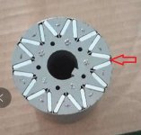
Im interested in your thoughts on this rotor , is it a good design for reluctance torque .
After watching the vid i posted earlier-- starts @ 17MIN they talk about having a good steel pathway avoiding the flux pinching affect That most spm's suffer with.,This qs ipm rotor seems to have a bad steel path way also for reluctance flux.?
 

Attachments

  • unnamed.jpg
    unnamed.jpg
    24.1 KB · Views: 1,560
marcos said:
The torque equation for IPM is this one. Note that if you zero Iq (torque-producing current), Torque goes to zero.
IPM torque.png

Thank you for making it clear how it works.
This makes me think that Nucular controller does FW not handle optimal at the moment (it is still beta), and Adaptto controllers with theire suggested speed limit of 120% too.

-----
another thread about IPM motor science:

https://endless-sphere.com/forums/viewtopic.php?f=6&t=95100#p1392739

I found it interesting that this guy was able to spin his 40kV motor up to 15k RPM with just 80V supply voltage :flame: :bolt: :thumb:

80V x 40kV = 3200RPM base speed
15000RPM / 40kV = 375V BEMF, which would be an insane 450% gain in RPM over base speed

He was using a controller with IGBT's (type: FNA25060) which also have body diodes regarding the datasheet (so no difference in terms of that compared to Mosfet controllers), however those IGBT's were rated for 600V which would mean the BEMF was still within specs.

Is the max voltage rating of the controllers Mosfet's or IGBT's relevant...?

kiwifiat said:
The Lebowski controller does not need a lookup table to achieve maximum torque per amp even for a salient pole motor like the Nissan Leaf motor...

Arlo could easy prove it with his car by taking it on a dyno.
He could do one run with 0% (or 0A) FW and one run with 50% (or a given value) FW current. Then doing a comparison of low RPM torque.
 
Emoto said:
liveforphysics said:
If the rotor iron is well designed for leveraging reluctance torque said:
Im interested in your thoughts on this rotor , is it a good design for reluctance torque .
After watching the vid i posted earlier-- starts @ 17MIN they talk about having a good steel pathway avoiding the flux pinching affect That most spm's suffer with.,This qs ipm rotor seems to have a bad steel path way also for reluctance flux.?


I don't feel qualified to determine that by looking at it. I can say it's improbable/impossible they achieved a high sinus% BEMF with the outside of the rotor being round.
 
liveforphysics said:
That's how you win at power factor on your drives output, but you win reluctance torque by leading it with current out of BEMF phase sync. However, aside from EMC harmonic generation, I don't think the hotrod EV user cares about power factor.

You're correct that power factor is maximized when the current vector is perfectly aligned with the voltage vector.

There are really two EMFs in a salient motor with permanent magnets (IPM)
The magnets in an IPM produce an EMF which is aligned with the q axis. This is traditional BEMF.
If there is current on the d axis, it will create an EMF on the q axis of w*Ld*Id, and likewise current on the q axis will create an EMF on the d axis of w*Lq*Iq. Let's call this reluctance-EMF (REMF, not a technical term)

In an SPM with no saliency, there is a large BEMF which is aligned with the q axis, and relatively small REMF which is perpendicular to the present current vector. We can get torque by aligning the current vector with the BEMF, but it is impossible to get torque from the REMF because it is inherently perpendicular to the current vector. In an SPM, the REMF only serves to reduce power factor and therefore the speed range of the motor.

In an IPM, there is still a BEMF which we can align to, but in this case Ld and Lq are different, so the REMF is not in general perpendicular to the current vector, and thus we can derive torque from this. This is reluctance torque.
Not only that, but the fact that this vector has a parallel component means it can be used to very effectively oppose the BEMF, leading to these motors' large field weakening potential and decent power factor.

In a traditional motor control system, we have an absolute encoder attached to the motor. To take advantage of the REMF (reluctance torque) we need to offset our current vector from the q axis, and normally a table is used for this.

If, theoretically, you had a perfect observer of the back EMF - it would not only be sensitive to the BEMF but also the REMF. This means the q axis observed by the observer would not be the physical q axis of the system, but would rather be aligned with this EMF. This should allow the system to naturally follow the MTPA trajectory, because it is not tracking the physical q axis of the rotor.

Of course, this doesn't work at standstill because there is no EMF to track. You will certainly need a table to maximize torque at standstill.

I don't know the details of how (or if) this works in Lebowski's controller, but that's the theory of why aligning to EMF produces max torque, even in an IPM. The reason this is not widespread is because developing observers which are stable, accurate, and robust to changes in speed, inductance, temperature, resistance, load, saturation, current, etc. is extremely difficult.
 
Well the last two post's say it all for me atm , as relying on this qs motor for the extra kv i needed is a bit of a gamble.
Add to that a more specific controller than your average foc is two much of a gamble for now, if i had close to kv needed id go for it,
Heading in another direction now.
Thanks for the input folks it was a education.
 
Emoto said:
Im interested in your thoughts on this rotor , is it a good design for reluctance torque .
After watching the vid i posted earlier-- starts @ 17MIN they talk about having a good steel pathway avoiding the flux pinching affect That most spm's suffer with.,This qs ipm rotor seems to have a bad steel path way also for reluctance flux.?
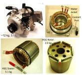
Hyundai HSG that showed significant stall torque increase have the wide pathways too.
I was wondering if QS 1000/2000/3000 is capable of low RPM torque improvement by FOC.
Looks like it is not the case :(
 

Attachments

  • HuindaiHSG.JPG
    HuindaiHSG.JPG
    93.7 KB · Views: 1,169
Back
Top