Fuse-wire for individual cells, DIY Tesla style

If the controller is only rated 20A, it shouldn't be pulling much more than that except for peaks during acceleration or hill climbing, and even those shouldn't be more than a small percentage above that, if the controller is designed and built right.

If it's able to pull a lot more than that, something is wrong with it's design or construction (like wrong parts used, shunt has solder down it's length, MCU programmed wrong, etc), or it doesn't actually do currrent limiting like it should for some other reason.

If its' only pulling 20A or so and still dying, then there's still something wrong, like needing more airflow, or crappy components in it, etc.

If the motors are getting hot they could fail by having hall sensors die, or by having windings burn up, gears melt (if they're geared types). Heat usually means putting too much current thru them under load, which means either too big a controller for them or too much load for the motor for too long, whcih can also mean wrong gearing (including wheel size) for the load and speed they're runningg at.

If they're failing for some other reason than heat, then that's probably a quality issue in manufacturingg, or a motor that's simply not built to take the torque/etc they'rre being used for.
 
spinningmagnets, where did you find that picture of the inside of an Alta pack? I have been reading some of their battery pack patents and I would really like to see any other pictures that are available.

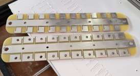
For those that don't know, Alta makes both the positive and negative connections at the top of each 18650 cell, and bonds the bottom of the cell to a heat spreading plate (rather than making positive/negative connections at top and bottom and cooling the sides of the cells). See https://patents.google.com/patent/US20140234668A1/ for more info.
 
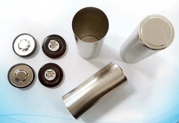
All the cylindrical cells I've seen, including every 18650, can be used that way if you want to, since the entire can is electrically connected to the "bottom" flat end (usually negative). You don't need a special cell to do it.
 
Yes, that is my understanding as well. I'm more interested in just any pictures possible of the inside of the Alta pack since they do several unique things. What does the cell holder look like, how are the cells bonded on the bottom? It seems like they did a lot of interesting things with the pack, check out this article about the thermally conductive epoxy they used: https://chargedevs.com/features/alt...ric-dirt-bike-has-world-class-energy-density/ . I'd love to see where they applied it. Probably at the bottom, but maybe between cells like potting?
 
Found the Alta battery pics on an Alta owners forum, and also the Alta section of an electric motorcycle forum. I'm on my phone right now, but both links are in the ES Alta thread in the electric moto section.
 
Thanks, was just looking through the Alta owners forum. Lots of good info and pictures. I wonder if they put anything between the bottom of the battery and the cooling plate besides the epoxy, to prevent the housing from making accidental electrical contact?
 
An interesting fuse style on this NASA PDF:

https://ec.europa.eu/jrc/sites/jrcs...on-resistant-designs-spacecraft-batteries.pdf

A thin fuse, and a thicker fuse, so the entire strand would be running hot at high amps, and as soon as the thin strand would blow, the thicker strand would run 20% hotter, finally burning. If only the thin section melted (but not the thicker section), it might be a visual indicator that you are running near the "blow" amp level...

Fuse18650A.png
 
Hello everyone. This is my first post here, I’ve been trying to find info on Tesla style fusing and this was the most info packed discussion I could find.

I’m an owner of one of the now defunct Alta Motors Redshift motorcycles. I’m also one of a few unfortunate owners who have experienced battery issues after the shutdown.

Apparently Alta was having some QC problems with their fuse wire bonding process that resulted in some failed bonds that went out the door without being caught. The failures showed up as a module imbalance after a change cycle.

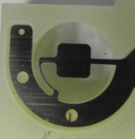
The failure in my battery is on the negative connection to one cell, it appears that the bond was attempted too close to the inside edge of the lip and it didn’t *take*.

My question is if anyone has any suggestions as to a possible repair? My first thought was a spot weld but a friend I have been consulting with expressed concerns about spot welding in that area as it may be a vulnerable spot. The fuse wire diameter on the negative end is .020”. I don’t know the wire composition at this point.

I have a picture to attach, I have to reduce the file size first. I will post it ASAP.

Thanks for any help!
 
Personally, I would attempt to solder it, but it looks pretty tight and accidental contact between the tip and the plate might be bad. The soldering process has to be fast enough to not melt the insulator. The original wire bonding process is done ultrasonically. The machines that do this are super expensive and hard to get dialed in.

Just curious, what is the pack configuration (how many series, parallel)?
 
4 modules, 21s 6p. 504 Sony VTC6 cells (cell type hasn’t been confirmed 100% yet).
 
It's my understanding that the Malectrics and kWeld spot welders have both been used to bond fuse wire to 18650's with successful results. I haven't tried that yet, but it may be worth looking into.
 
spinningmagnets said:
It's my understanding that the Malectrics and kWeld spot welders have both been used to bond fuse wire to 18650's with successful results. I haven't tried that yet, but it may be worth looking into.

I have been favoring a spot weld for the repair. Concerns were expressed about attempting a spot weld at that location on the cell, and since that orientation appears to be unique to the Alta finding anyone who has experience doing it like that seems unlikely.

The other thing I would need to determine if I go the spot weld route is what to use for fuse wire. I would need to dial in an appropriate setting on some junk 18650’s before attempting the repair.
 
For sure try to dial in the weld setting on some junk cells. Do you know what the bond wire is (material, size)? You can possibly measure the diameter of the existing ones.

You'd also have to figure out where to put the second welding electrode.

Placing some kind of insulation, like tape, over the positive contact or anyplace else things could short out would be a good idea when working on it.
 
Altaowner said:
Here is the picture of the failed negative fuse wire bond;

Yikes, that looks tight. I agree that spot welding a nickel strap from PCB to cell might be the easiest repair, unless you have a friend with a wire bonder. :D
You will probably need some tiny spot welding electrodes to fit in that space, though.
 
fechter said:
For sure try to dial in the weld setting on some junk cells. Do you know what the bond wire is (material, size)? You can possibly measure the diameter of the existing ones.

You'd also have to figure out where to put the second welding electrode.

Placing some kind of insulation, like tape, over the positive contact or anyplace else things could short out would be a good idea when working on it.

I do not know the material yet. It is .50mm in diameter.

I had another suggestion that would be more of a mechanical repair, which would be to create a conductor out of "wavy" nickel plated spring steel and push it down into the venting shaft and attach the fuse wire to that conductor. This would be a conservative approach, the main concern though with this would be ensuring that the conductor would stay in place. Any soldering/spot welding could then be done without concern of compromising the cell.
 
Can you get to the bottom of the cell? If so, you could spot a nickel tab and solder to that and run a wire up to the connection point.
 
fechter said:
Can you get to the bottom of the cell? If so, you could spot a nickel tab and solder to that and run a wire up to the connection point.

No unfortunately that is not an option.
 
As far as where to put the probes, I would file a shallow slot into the tip of one probe to "hold" the fuse wire. Press the fuse wire down against the shoulder of the cell, and place the other probe on the cell shoulder just a short distance away.

What's inside an 18650 cell
https://www.electricbike.com/inside-18650-cell/

Battery1865018.png
 
I wouldn't recommend the wavy spring method, though it would probably work for a while. Long term the contact would be prone to degrading.

To get both welder electrodes on the rim of the cell it looks like you may need to move the connection point over a little. This should work well if the welder is properly dialed in.

I still think soldering would work well since there isn't much thermal mass and you could make the connection quickly enough to not damage the cell, but there is some skill involved. This could also be tested on a 'crash test dummy' cell.
 
fechter said:
I wouldn't recommend the wavy spring method, though it would probably work for a while. Long term the contact would be prone to degrading.

To get both welder electrodes on the rim of the cell it looks like you may need to move the connection point over a little. This should work well if the welder is properly dialed in.

I still think soldering would work well since there isn't much thermal mass and you could make the connection quickly enough to not damage the cell, but there is some skill involved. This could also be tested on a 'crash test dummy' cell.

I do have a close contact who is has a skilled hand and does circuit board repair. I will probably show it to him and see what he thinks. I DO NOT have the skill to attempt it!
 
Just practice on a handful of old cells. whether you spot-weld or solder, you will achieve good results with a little practice.

If you go the solder route, you must use a high-amp soldering iron with a lot of tip-mass (fat tip, not a sharp point, mine is 100W). If the tip mass is too small, it will cool off fairly quick when you touch the subject. That would force you to keep the hot soldering iron in contact with the cell way too long. Doing that allows the heat to penetrate too deeply into the cell.

High heat from a fat tip will accomplish the soldering connection very fast, and that is the goal. Experiment on old cells, and I think you may be pleasantly surprised.
 
Altaowner said:
I do have a close contact who is has a skilled hand and does circuit board repair. I will probably show it to him and see what he thinks. I DO NOT have the skill to attempt it!
Should all rescue attempts fail, you could disconnect 1 cell from every series in this module (I suppose those modules are 4 in parallel) to get balanced and going again, sacrificing ~4% of pack capacity.
 
Back
Top