Votol EM-100 & EM-150 controllers

Hi Everyone,

I am facing another challenge while connecting the speedometer : I have bought the following one
https://www.aliexpress.com/item/48v60v72v-84v-96-vdisplay-with-wind-shielding-cover-for-electric-bike-scooter-little-turtle-king-instrument/32870366298.html?spm=a2g0s.9042311.0.0.2aee4c4dVYrbNc

The meter is working fine except the speed. When I connect the hall sensor wire of the speedometer (hanging pink wire in the pictures of the aliexpress link) to the (white) single line hall wire of the EM100 controller, I am getting values in the range of 143 kmph for speed, even without throttling.

I tried calibrating the potentiometer inside the speedometer but it seems that only top speed can be calibrated I bought the value of 143 down to 65 (kmph) at zero speed, but it is not going less than that.

Let me know if I am doing something wrong with the wiring or anything else. Thanks in advance !
 
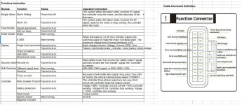
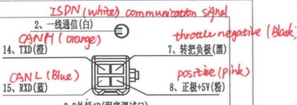
Yes I checked , it says ‘single line transmission signal (white)’ in the excel I received from vendor. In the wiring diagram you shared earlier it says ‘ISDN (white) communication signal. :(
 
Please make a screenshot picture on the excel, could be interesting.

I think you normally need a hall sensor and magnet placed at the wheel to get it to work.

Possibly you can also connect to a motor hall and try to trim the setting on the speedo to get the correct speed (might work, might not)

Let's see.. Each hall changes state one time for an electric rotation, for a qs 3000W mid motor it's 5 times per mechanical rotation. If you gear it down roughly 1:5 to the rear wheel (as an example) you have 5*5 signals per wheel revolution.. I guess it is possible to do it that way :D
 
I'm pretty sure you're supposed to take a Motor Hall output for speed measurement.
That is how most LCDs do it.
 
Yes eee291, that is what I did with my past experiments, but this time its a bit different for me :(.
Thanks larsb, I am attaching a screen shot of the excel.

Meanwhile interestingly I found a approach to get this right. I used the 'motor move signal wire' which is integrated in the anti theft wiring of the controller and connected it to the hall wire of the speedometer. Also, I connected the speed wire 'purple' of the speedometer to the ‘single line transmission signal (white)’.

It worked for me, but there is a small lag in the display.
Let know what do you think.
 

Attachments

  • PS_1.jpg
    PS_1.jpg
    182.9 KB · Views: 13,532
Hi everyone. I’ve got a QS motor with the same controller installed and working fine. These posts of you guys was very helpful in setting things up.
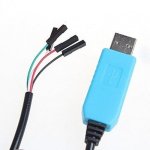
I would like to get into the controller to limit it’s speed and acceleration. I’ve bought a pl2303 cable and also have a controller with only 3 cables. My question is regarding the wires. In the picture of Larsb I can’t really see which color goes where. I think I know which color is which function but can one of you confirm?

On usb cable Green is TX, so transmit and this goes to CAN H, orange on the controller.
White is RX, so receive and this goes to CAN L, blue on the controller.
Is this correct?
 
larsb said:
You need to cross the cable connections

15. Rx controller --> Tx usb
14. Tx controller --> Rx usb

Thanks Larsb. Being the impatient guy I am I went ahead with my proposal just before you replied. That means rx controller —> rx usb
And this works. Maybe green on the USB isn’t TX but RX?...
As it is working I assume it’s ok. Or maybe it works no matter how connected?

Also... feel stupid I didn’t see the TXD and RXD text on the drawing before... I only saw the pen writing...

But thanks again!
 
Thanks Larsb for the referral.
Hello guys, As mentioned before I have the QS 3000W motor with the Votol 150 controller and I’m trying to get the right settings.
It’s build in a little car with weight of 280kg without 2 passengers so max weight is 430kg including passengers and battery.
I’m going for a max speed of 47km/h.
Long range is important.
Acceleration speed is not important, similar to a 50cc 4 stroke standard scooter is good.
Battery is 72v 100ah, capable of 410A output.
Currently my range is 80km, during 150 minutes, had not hills in test. This seems low to me and could be improved, what do you think?

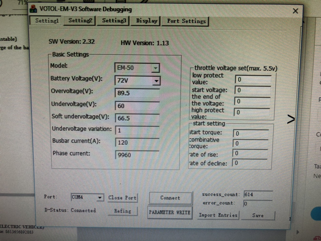
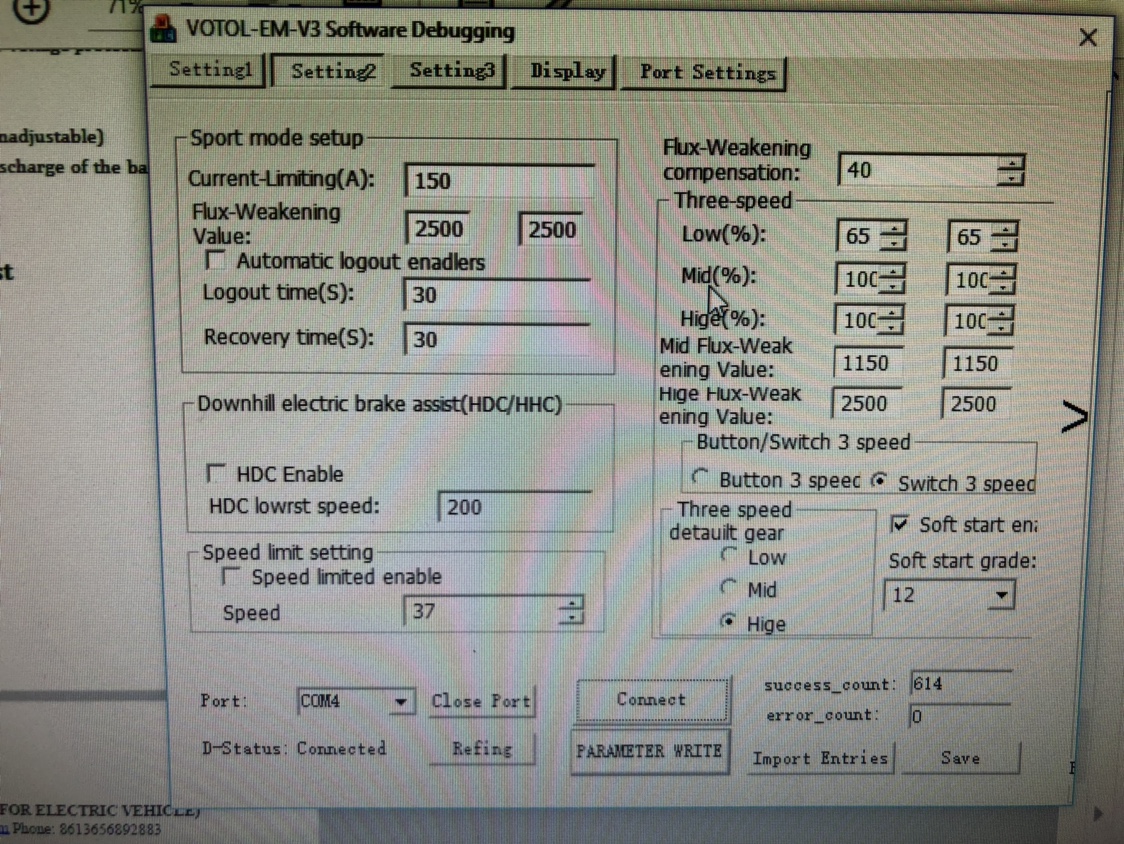
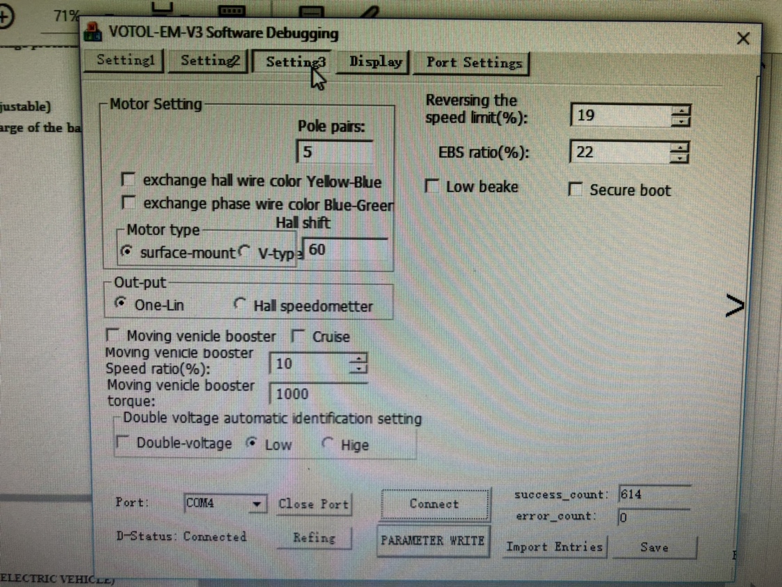
I’ve got access to the controller and have been fiddling around with the settings. Some I understand but not all, below pics of the settings.
Phase current on settings page 1 is on 5000 (what does this number mean?
On page 2, all three speed % is set on 67% ) gave me top speed of 47km). Why are there 2 columns?
I have no idea what flux weakening does.

6060f838b80aaf158177d2e0db7c3d97.jpg

abfa6bcbc2863d038d93e77ba1cd6530.jpg

03d9f99ecbecb7ff8b0379e4fc546526.jpg


I’m hoping for some help and advice, many thanks in advance!
 
Some answers are in the manual, did you check it?

I could go 60km on 72V35Ah with this combo on my moped. You have triple the weight and 4 times the contact surface on the tires. Hard to say what's reasonable in range. Does motor get varm?

The phase current setting is just a representative value, my controller was set at something like 9600 when i got it, i think this is max setting since controller returned to this when i tried to increase the setting.

Field weakening increases possible speed of the motor, often at the expense of torque and efficiency. There's an ongoing discussion if this motor is good for field weakening, since it is interior magnet motor it could be efficient and gain torque in field weakening if motor design is optimised for this. I don't think it is but cannot prove it.

The three value settings are set related to the voltage level, if you have low battery then controller will adapt the output according to these three settings.

Read the manual :D
 
If you do the math you consume 90Wh/km which sounds reasonable for a 400kg car.
I consume ~55wh/km on my moped going 50km/h
 
Thanks for the info. If I read it correctly then I am on the right way. To get to a steady 47km/h with low power consumption as possible I can change:
To get right speed:
1. % in three speed settings

To get power consumtion as low as possible, which will cost acceleration
1. busbar current
2. phase current

All other settings I don't have to change? Agreed?


About notes:
larsb said:
Some answers are in the manual, did you check it?
Yes, RTFM, Read The frocking Manual, is my mantra :D
But I still got to those questions, for instance:
About the phase current the manual says: (2) phase current limited value: if limit controller phase current out-put, it will limit the motor torque out-put. Setting Range (the biggest value full power out-put, don’t suggest adjust )
Doesn't say anything about what the unit used is.

larsb said:
I could go 60km on 72V35Ah with this combo on my moped. You have triple the weight and 4 times the contact surface on the tires. Hard to say what's reasonable in range. Does motor get varm?
Not really, you can touch it with a bare hand. I'll have to check this during a next test.

larsb said:
The phase current setting is just a representative value, my controller was set at something like 9600 when i got it, i think this is max setting since controller returned to this when i tried to increase this setting.
Standard setting when first connected was 9960. I changed it to 5000 to limit the acceleration and speed up a hill. I think I'm going to lower this setting. During testing I noticed that below 1000 the motor wouldn't turn with wheel off the ground.

larsb said:
Field weakening increases possible speed of the motor, often at the expense of torque and efficiency. There's an ongoing discussion if this motor is good for field weakening, since it is interior magnet motor it could be efficient and gain torque in field weakening if motor design is optimised for this. I don't think it is but cannot prove it.
I'll leave that standard setting then.

larsb said:
The three value settings are set related to the voltage level, if you have low battery then controller will adapt the output according to these three settings.
This I could have seen in the manual, it's there:
The range for flux weaken value on left/right side refers to in dual voltage mode, the speed is different
because of the different voltage. Left side option refers to low voltage, right side option refers to high voltage.
For single voltage controller, Please keep the left/right in same value.

But how to tell if I have a single voltage controller? I think this won't give me a better range, so not that important.

eee291 said:
If you do the math you consume 90Wh/km which sounds reasonable for a 400kg car.
I consume ~55wh/km on my moped going 50km/h
OK, interesting. I'll look for some more comparable consumptions. Thanks
 
To get right speed:
1. % in three speed settings

You get best efficiency by running the motor at the right load and rpm. The qs dyno values indicate that best rpm is around 3500. I think you could try to gear to get this rpm at your preferred speed and not limit speed by percent setting. It is very limited data so i cannot say how wide the high efficiency span is though and what loading is optimal so it's a guess :D

Also "lean driving" for combustion engines should work the same for an electric vehicle - get your motor up to the high efficiency band ASAP by accelerating fast. Slow acceleration is not necessarily better for efficiency and range.. but surely less fun :wink:

I don't think you can win much by tweaking the settings. If you had a dyno then some tests with different phase angle setting could be done but without this it's really hard to optimise.
 
Hii..
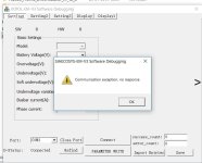
I'm working on VOTOL EM-100 controller with 2000W motor. I already operated the motor, Now I want to access the controller. The problem is EM V3 shows the message as attached. Please give the suggestion.
sc1.jpg
 
Could be serial adapter is not working correctly or wrong com port selected.. Apart from this I don't have other guess..
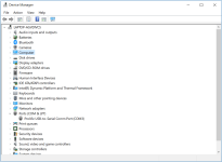
Can you see the serial adapter in device manager? Are drivers updated?
Is the serial adapter connected on same port as you have chosen in program?
 
larsb said:
Rosh: it's because you're both at the same IP address

Now that's a coincidence..
come on! stuff like that makes me less than willing to help. I'll just dial out of this thread for a while.
Thanks Mark5.

Not sure why anyone would make a double account, maybe to get the idea out it’s very important or maybe they are two separate people in a big building with shared internet, maybe a school?

Just wanted to let you know that I value your replies a lot guys. Because of the info in this thread I got my motor and controller connected very quickly and right first time.
Thank you very much for that.
 
larsb said:
Could be serial adapter is not working correctly or wrong com port selected.. Apart from this I don't have other guess..
Can you see the serial adapter in device manager? Are drivers updated?
Is the serial adapter connected on same port as you have chosen in program?

serial adapter is connected and working properly. Drivers are updated. Serial adapter are connected on COM 3 (By default) same is selected in program. I have downloaded the application from dropbox whether it may lead problem ?
shearing the photo of connections.
sc2.png
 
larsb said:
image.jpeg
I think you need to cross the cable connections

15. Rx controller --> Tx usb
14. Tx controller --> Rx usb

Did you build the cable or did you get it from seller? I am not sure it needs to be crossed and some cables don't have the "normal" colors for rx and tx. You could try to switch what you have now to see if it works.
 
Also, has that particular usb-serial adapter worked in the past or is this the first time it's been used. Try another driver. Or try a different usb-serial adapter (e.g. FTDI vs Prolific) & driver.
 
larsb said:
can you drive the motor when you try to program?

On that subject, can you? Because I can’t drive the motor when I’m conntected and I’m going to test the motor during a power test. It’s nice to see the display page on the PC while using the motor. This display page does show live rpm but only if I manually turn the wheel, can’t use throttle.
 
Back
Top