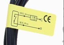
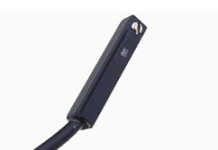
how do those "Pneumatic-Cylinder-Magnetic-Sensor-Reed-Switches" work?

izeman

1 GW
Joined
Jun 21, 2011
Messages
5,131
Location
Vienna, Austria
Bought two of those to use them as a reed switch for ebrakes in combination with a Cycle Analyst.

https://www.aliexpress.com/item/1PCS-CS1-G-1-5m-5V-240V-DC-AC-Pneumatic-Cylinder-Magnetic-Sensor-Reed-Switch/32905509816.html?spm=a2g0s.9042311.0.0.17494c4dEOKtZP

Screenshot from 2019-02-11 22-00-18.png


But it seems they are not to be used like "regular" reed switches. They may need some power? But how much? And how will it sense the switching?
I guess it is just not useable for my application?

Any advise someone?
Thanks!
 
The specs look like a normal reed switch. It only has two wires. It does say 5v -240v AC or DC

Reed switch.jpg

If you measure ohms across the wires, it should show continuity when you get a magnet close.
 
I ordered two. And they look quite legit. And they were quite pricey as well. I will do some more testing.
Maybe they really need stronger magnets. I'm also wondering what that screw is for? Any ideas?

And does THIS make any sense to you:
Installation attention:
The quick connectors at the end of the line are all three needles, one male head, straight line and one rotatable screw tooth type, and must be ordered in addition to its matching inserts.
 
I think they are saying you have to terminate the wires yourself.

Some magnetic switches are polarity dependent, meaning the magnet direction matters.

No idea what the screw does, but you might try removing it and looking in the hole to get a clue. It might possibly change the sensitivity.

It also says something about a LED indicator. If the switch is NO, then the LED would be across the wires? This could be tested with a power supply.
 
Hmmm. Thinking about that. What puszzles me, is the LOAD mentioned on the sticker. There is no load. The CA is just checking for not/shorted. So it sends a 5V signal into the switch and checks the input pad for high/low afaik.
I'll take out the screw and then check with it directly connected to the CA.
 
Not sure, but the presence of the LED indicates it would be polarity sensitive. That said, it'd be normal for these things to take 5VDC. It seems a little strange you could supposedly put 240V and not fry the LED (if not the switch contacts).

Here's how the magnets in a pneumatic cylinder work: https://www.hydraulicspneumatics.com/cylinders-actuators/sensor-choices-pneumatic-cylinder-positioning
 
Don't know what went wrong with my first tests. Those switches work as you expect it. Move a magnet close to them and they switch. Once it's closed, a super tiny LED turns red. Using them as an ebrake switch should work in case you can find a good location for the magnet as the sensing direction is mainly on the long side of the sensor, and not the ends. And the magnet has to be quite strong as well.
 
Back
Top