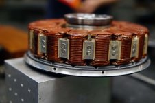
APL's DIY axial-flux motor

Also, I wanted to follow up on the anodizing process, in case anybody is planning to try it.

I tried boiling the parts in a weak mixture of Simple Green and distilled water for about 5 - 10 minutes, and
that worked like a charm. It's amazing how clean that SG will get aluminum!

Then I put it in the sodium phosphate for three hours on the 2 amp setting, which shows up as about one amp
on the charger meter. That changes with the size of the part. The part will have a yellow tint to it when it's
ready for the dye. The longer you leave it in the anodizing tank, the better it turns out.
Use distilled water for everything.

I imagine different kinds of aluminum will act differently to the process.
Now the problem is getting two pieces with a matching color. :roll: It would be wise to do all of the pieces at the
same time, through the system, if you wanted equal tints.


I bought 2 lbs of sodium phosphate on the bay for about $12. and used about three quarters of it. The solution
doesn't seem to degrade,.. or at least, hasn't yet.

I plan to do the rotors in a very light gold, and the bearing caps in red. Ooooh :)

Rotors are up next, at long last!
 
APL said:
Also, I forgot to mention that I thought the segmented magnet Idea was a good one, and doing some cutting
would clean it up a bit. As a DIY guy, I tend to think 'off the shelf', but if you say custom made magnets are
not that expensive, then that would be a game changer.
I would avoid to cut or grind on magnets because they are brittle and hard and the dust probably isn't good for health.
With magnet segmentation you can get out the last bit of performance or efficiency.

I did this on my RC midmotor together with changing the pole count from the initial 16P to 20P. I was using 3 pcs per pole.
The costs for those custom mangets were around 70USD shipped to my door (N42SH grade with raw epoxy coating).
If you do this, be aware that segments will repel from each other which makes it a pain in the a** to glue them side by side.
At the beginning i planned to use 4 pcs per pole, but gluing them side by side was impossible and so i decided to go with 3 pcs which still took some own technique for the installation.


I'm not sure about how the segmented core idea is supposed to work though,.. are they talking three sets of
laminations?

Yes it looks so. Those three sets you could mill later to trapez shape.
As you are making this motor from ground up with alot of effort as it looks, i would take a closer look to the design of a yasa, emrax or magnax motors :)
 
Edit to first post; 'Sodium Bisulfate',.. not phosphate,.. my bad.
 
I've studied those motors,.. very nice corporate builds, and certainly lots of ideas there, but most rely on a
preparatory part thats out of reach, like the Yasa giant center bearing, or the stator assembly can't be seen for
study. Not off the table though.
Mostly interested in outrunners, but will consider anything, if it can be converted to DIY, or done easier.

The Emrax has an interesting core mounting system that I haven't seen, it relies on bonding, and thick wire though.
Still,.. I'm putting it on the list.


Emrax motor.jpg


Also, trapezoids are the preferred shape, and most all corporate offerings will have them, but it's not a 'must'
There are several built this way.


View attachment 1
 
Nice job on your motor conversion madin88, I'm surprised that you could keep the air gap,.. I suppose thats where the
'custom' size comes in. Curious as to what kind of glue you wound up using?

It has always boggled my mind how there can be more, or less, PM magnets than there are teeth. In my mind there should
be an equal number of each, and that any 'extras' would just serve to clog things up.

A two pole has two, a four pole has four, single phase. But it goes by numbers of three, (teeth), and pairs of two, (poles),
three phase. Some combinations are better than others, but all will apparently work.

I know that it has something to do with placing the PM magnet in between the tooth profile, but that would only be for
a few. What about the rest? I just have to go on faith,.. thats the way it's done, and move on.
 
APL said:
It has always boggled my mind how there can be more, or less, PM magnets than there are teeth. In my mind there should
be an equal number of each, and that any 'extras' would just serve to clog things up.
If they were all the same, they'd all line up, and the fields would "stick", so it would not rotate. If it was not lined up then as soon as it *did* line up, it would stick, and stop rotating.

So different numbers are used to cause rotation to occur.

You might be able to make it work with the same number, but it wouldn't just automatically begin rotation; it would require the controller to be smart enough to force this. In certain perfectly-aligned situations it might require an external force to misalign them to allow the controller to do it.
 
I see, that makes sense. It sounds like theres a certain amount of efficiency being sacrificed for rotation,.. but
since these motors are in the high 80-90% range, thats probably not true.

Funny that in all the searching I've done for these motors, that there hasn't been any mention about this aspect.
Perhaps theres a term for it.
 
Unfortunatley Powercroco.de is gone; it had a lot of info on that site including calculators for such things. Wayback machine says the site was excluded (meaning they chose not to be archived). :(

RCGroups.com has a LOT of threads about rewinding or even building motors, but all the ones I can find that are relevant don't state the info, they link to powercroco instead. :/

There is other info, including winding direction, etc., discussed here:
https://www.wattflyer.com/forums/archive/index.php/t-14434.html
among other places, which links a couple of good threads itself:
https://www.rcgroups.com/forums/showthread.php?240993-%28Re%29winding-and-building-motors-tips-tricks-checks-tests
https://www.rcgroups.com/forums/showthread.php?454778-DIY-motor-tools-and-parts-sources

but I don't directly see the info to explain what I was talking about. :(
 
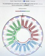
The site from the link below contains some basic infos about motor design, and there is a winding simulator where you can enter a given slot and pole count, and it will tell you how efficient the windings will be in producing torque. A winding factor of 100 would be the best, but most motors have something in between 90 and 95.
Check it out:
http://bavaria-direct.co.za/scheme/calculator/

amberwolf said:
Unfortunatley Powercroco.de is gone; it had a lot of info on that site including calculators for such things. Wayback machine says the site was excluded (meaning they chose not to be archived).

Yes it is too bad that powercroco got closed. There were so much infos about how to wind motors, which wires or sort of winding work best, which tools you should have if you want a neat winding with high copper fill, etc etc.
They mostly worked with RC motors, but what applies to small motors also applies to larger EV motors.
Sometimes google seems to find some remaining contents of this site or at least it directs to pictures from there.
There is also another board called "powerditto" where you might be able to get some motor knowledge from, but it is by far not that big as the croco board was..
 
Thanks guys, all this info is just in time! Madin88, that calculator is just what I need. I'm at the point of wiring up the
stator, and now I'm having second thoughts as to how to do it.

I wanted to go with a wye configuration, and a straight up series coil route on this axial. Theres no left and right
turns for teeth. (although delta isn't any harder to do either)

I chose the 21T-26P combo, because of the winding factor, and torque ripple values. But it shows an odd wiring circuit
on this calculator.

Entering the numbers into the calculator for a 21/28 combo yields a better wiring circuit, (series), but a lower amount of
'cogging steps' (not that I care that much about the wiring, but I like simple)

My question is; is it better or worse to have a high or low number of cogging steps. I assume that a high number is
preferable, as it would be smoother,.. from what I've read so far, cogging is not an indicator of motor efficiency,
or toque?
(This is a mid drive motor, so motor 'drag' isn't a real 'big' deal, although less is always better.)

21/26 = .88925 winding factor. 546 steps per turn. odd circuit.
21/28 = .86603 winding factor. 84 steps per turn. simple circuit.

Winding factor is relatively the same, but the steps per turn are a big difference. Can anybody chime in on that?

I've got the stator wires roughed out, for series, and everything fits well in there, I found some thin plastic sheet for
an insulator between the coils and stator aluminum. Now I just need to cut the wires and do the dreaded tinning.
I'll wait until I get the above worked out though.


Once I get this thing wired up, I figure I can hook the controller up to it and crank the throttle back full.

Hopefully, I can use the laser thermometer to see what kind of heat it generates in regard to the 1T, or rather
42T, delima. Unless the controller needs to see the load from the rotors?
 
Well, the controller won't run the stator unless it sees the rotor moving in reaction to it's attempts, because it can't know how to commutate teh field otherwise, and will shutdown to prevent damage to motor and/or controller.

If it's sensorless, it needs the magnetic field feedback from the rotor magnets into the phase coils of the stator to determine position and speed.

If sensored, then it needs the feedback from those sensors (which usually use the magnetic field feedback too, like with the common three-hall-sensor arrangment of common ebike motors).


You can, of course, fake the feedback into the sensor wires of a sensored controller, using a shift register or similar type of circuit, if you don't have a rotor yet.
 
APL said:
21/26 = .88925 winding factor. 546 steps per turn. odd circuit.
21/28 = .86603 winding factor. 84 steps per turn. simple circuit.

26P looks indeed odd, but it should be the better choice.
If you click on "advanced", you can see the winding factor of other pole counts and you also can enter stator diameter and slot opening (the gap between the stator teeth). The larger the gap, the less effective the winding will be.

btw: i would use a star termination because in delta there could occur circulating currents within the windings.
 
Those are low winding factors.. You'd get about 0.97 in the best concentrated windings and get more of every goodness :D

Example 21slots/22poles is better with 0.95

Check here:
https://www.emetor.com/windings/

If you cannot get this high due to your already chosen configuration then this should be changed for version2

More cogging steps-->lower torque ripple is good but not as important as above.
 
Thanks amberwolf, I suspected as much, but wasn't sure. Well,..I'll just have to wait till D-day and get all the news
at once. I still have options for some of the problems there.

Madin88, yes, I've been searching all the different combos, and it looks like the 26 - 28P's are the two most likely.
I would plug the slot opening in but they are angled, and I 'm not sure how to work with that.
Thanks for the input,..the 26P is probably best, even though I don't like the circuit.

Larsb, that is an awesome link!, I'll be studying that for a while,.. wish I would have seen it earlier.
I was aware of the 21/22 combo, and I ran across it a while ago,..the winding factor is the best. But after reading a
paper that stated instability in magnetic pull, I had decided to abandon it. Perhaps I was too hasty?

https://www.researchgate.net/publication/4289947_Guidelines_for_Designing_Concentrated_Winding_Fractional_Slot_Permanent_Magnet_Machines


I really 'stepped in it' when I decided to go with 21 slots instead of 24,.. foolish APL, well it is what it is,.. live and learn. :)

Well, I'll study all this for a while,.. meanwhile, I'll get going on the rotors and back iron rings, hopefully it will get worked
out by the time the PM's are ready for glue.
 
After looking at the circuit for a 21/22P arrangement, I think I can see what they're talking about,.. it's like a
giant three pole motor. It's probably better to distribute the forces around the diameter more.


IMG_1668 copy.jpg


It's like Goldilocks and the three bears,.. I guess I'll lean towards the middle one, 21/26P. I'm not after the greatest
efficiency at this point, and the back iron's can be changed out with a different magnet count, I might even be able to
just 'burn' them off, and glue on some new ones. Changing the circuit will be a little harder though.

Another disappointment today when I looked closer at the magnets I bought for the rotors, they're not 10mm wide,..
they're 9mm, and instead of 40mm, I get 39mm,..thinner too.

What up? They got pee wee rulers over there? :lol:
Maybe it's Einstein's relativity theory, that states things getting smaller in one direction, and larger in the other.
 
I've tried the same.. Got magnets intended for a tight halbach that was out of dimensions like your magnets.. Just useless.
It's necessary to buy from known sellers or direct from a manufacturer, i didn't.. But if you want to keep special dimensions then it's hard.

I guess a lot of the magnets out there are actually rejected as second grade and sold on through places like aliexpress or banggood
 
That's to bad,..in a Halbach theres no room for error. I guess this is another reason to go with custom made magnets
like madin88 suggested, then at least we get what we want.

Well, now that I know,.. I could order the next larger size, which would be undersize, but slightly larger than the cores
I have, which would be just about right since I need a little overlap anyway. :roll: Crazy.

Recon I'll use up what I have, because I need the gluing experience, and the motor will 'spin' regardless. I'm pretty sure
I can melt them back off with the heat gun, or at the worst,.. the torch, wouldn't hurt to anneal the rings anyway.
They only cost $35., so it's not a big loss.

The next size up is $100., so I don't want to cough that up until I see some spin action. Then I'll be happy to upgrade.
Luckily, these rotors have room to accomodate some small size changes.
 
APL said:
Curious as to what kind of glue you wound up using?
as glue i used Loctite 438
I bought magnets with epoxy coating and with a bit of grinding and cleaning i got great results. When i had to remove a few which i assembled wrong i had to realize that the glue joint was stronger as the magnet material itself.
 
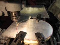
Another cold snap, and a stove pellet shortage,..I'm ready for spring! But I was able to at least get started on
cutting out the rotors. I had to buy 12x12 flat stock this time around, and the lathe is to small, so I had to cut
them out the hard way, and double hand wheel it on the mill. A bit tedious,.. but not much effort involved.

A little clean up on the belt sander, and they're ready for the lathe. Going to be tight though, I'll only have an 1/8"
or so to spare for bed clearance.


Rotor cut..jpg

I'm happy to be chewing up some aluminum again,.. and I feel like I'm getting somewhere.
 
I would have never thought of making an axial stator array like this!

https://www.youtube.com/watch?v=XgUky1jUOW0
 
APL said:
I would have never thought of making an axial stator array like this!

https://www.youtube.com/watch?v=XgUky1jUOW0

Well, of course. Doesn't everybody have an automated ribbon steel punch in their garage?
 
I wish!!! Just one size notch, and everything lines up perfectly,..amazing.

When I think of all the trouble I had to go through, and this thing just spits it out,... :x
 
Weathers finally warming up again, and I can get back out into the shop. I made some headway on the rotor
and back iron ring,..one side anyway.


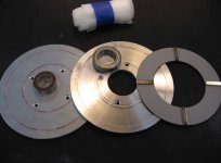
Rotor and Back iron.jpg

The back iron recesses into the rotor to keep everything balanced. I'll need to put some ventilation holes in
the rotor yet, but theres not a lot of room on the big bearing side. Bearing cap mounting holes, outer spacer,
and back iron mount holes come later.

I'll probably mill some recessed slots on the outside of the rotors, to reduce weight, and break up the 'slab' look.
 
Back
Top