Help whit Gazelle BMS

s3v3n

10 µW
Joined
Mar 24, 2019
Messages
6
Hello, guy.
Anyone can help me?
I have Gazelle e-bike like photos.
The BMS is not working, i want change for normal one but i see that blue wire :shock: what should i do whit that one? Why is there ?
 

Attachments

  • 54463072_2134467439924465_1585123234674638848_n (1).jpg
    54463072_2134467439924465_1585123234674638848_n (1).jpg
    43.1 KB · Views: 802
  • 54730013_569593586857981_5790294953632464896_n.jpg
    54730013_569593586857981_5790294953632464896_n.jpg
    34.8 KB · Views: 802
  • 54463072_2134467439924465_1585123234674638848_n.jpg
    54463072_2134467439924465_1585123234674638848_n.jpg
    43.1 KB · Views: 802
There's a fair probability that that battery uses some sort of communication with the controller, and/or it has remote switching. If you're re-celling the battery, it's best to use the original BMS and wire it the same as it was.

tell us what you're trying to do so that it's easier for us to give you any advice you need.
 
I was thinking the same, but is no BMS clone of that one in market. 99% is dead battery :x

I need to repair is for my e-bike all cells are excellent +2000mah. New cost around 600.00 euro :oops:
 
What is the thing the blue wire goes to? I only see the back side in the picture. Many BMS have a separate wire for charging.
 
fechter said:
What is the thing the blue wire goes to? I only see the back side in the picture. Many BMS have a separate wire for charging.
Is the Discharge to bike.
 
Hard to say without some testing, but the blue wire may be sending data to a battery meter on the bike. With a replacement BMS, you would lose this feature. My A2B had something similar. I use a separate battery meter now.
 
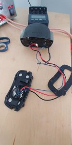
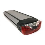
I'm not seeing any BMS here. Looks like the last picture shows that you unsoldered the red/black wire from the battery which goes to the rear of the pack, where you probably have a tail light, a charge port, and maybe an on/off switch?

Based on batteries I own, there ought to be at least four wires between the rear part and the cells.
(1) Battery power (2) ground (3) charger ground (4) battery ON. You're only showing the red/black which are the first two.

That would suggest the BMS doesn't use an on/off and the cells are always on. The blue wire could be the on/off circuit to the controller to turn it on. If that's true, this design always gives you live power at the plug. Seems unsafe. Now if there's more wires you didn't show coming from the rear piece that goes to the battery, then I am wrong here.

Also if there are only two wires going to the cells, the pack would have to charge and discharge thru those two wires. It can be done, but it would complicate your selection of a BMS. Many have separate return wires for the power and the charge connectors,

Anyway, these pictures have not have not unveiled the BMS and do not give the viewer a clear idea on how this pack is connected.
 
Based on the numbers of wires, it looks like the BMS is in the other end of the case.

Every BMS I've ever worked with had a separate light gauge sense/balance wire to each cell group.
 
This threat is old but I nevertheless wanted to add some information.

The blue wire from the BMS board (embedded in some black resin on the newer battery models) is the communication signal between the BMS board and the controller that is embedded in the front motor. I assume it's used to report the battery level to the controller and display. It likely also tells the BMS board to turn the backlight on when the lights are turned on using the controller button. There is a small 13 pins connector going from the batteries to the BMS board that is used to balance the cells during charging. Without the proper communication on the blue wire, the system will likely show some sort of battery error and will refuse to give assistance.
 
Back
Top