
You are using an out of date browser. It may not display this or other websites correctly.
You should upgrade or use an alternative browser.
You should upgrade or use an alternative browser.
Rectifier Huawei R4850G2 48V 42~58V 3000w
- Thread starter vicens
- Start date
Added info parsing, bluetooth and wifi serial:
https://github.com/BotoX/huawei-r48xx-esp32/commit/f2741078a123bfcc90fcd496486d9cd2b6373a87
Efficiency is shit at low power, transistors on the low voltage side get really hot ???
Some inbuilt description in the PSU:
Really funny how at 10A there is 26.5W loss and at 5A there is 33W loss...
But I guess that info is in the datasheet graph too.
Edit: 6A 94% efficiency, guess it's something hardcoded lol
https://github.com/BotoX/huawei-r48xx-esp32/commit/f2741078a123bfcc90fcd496486d9cd2b6373a87
Code:
Input Voltage: 226.06 V ~ 50.43 Hz
Input Current: 2.45 A
Input Power: 554.77 W
Input Temperature: 22.00 °C
PSU Efficiency: 95.21 %
Output Voltage: 51.54 V
Output Current: 10.12 A / 10.00 A
Output Power: 528.22 W
Output Temperature: 35.00 °C
Efficiency is shit at low power, transistors on the low voltage side get really hot ???
Code:
Input Voltage: 225.94 V ~ 50.43 Hz
Input Current: 1.31 A
Input Power: 295.10 W
Input Temperature: 24.00 °C
PSU Efficiency: 88.87 %
Output Voltage: 51.11 V
Output Current: 5.08 A / 5.00 A
Output Power: 262.24 W
Output Temperature: 45.00 °C
Some inbuilt description in the PSU:
Code:
/$[ArchivesInfo Version]
/$ArchivesInfoVersion=3.0


[Board Properties]
BoardType=EN1MRC3G1A2
BarCode=2102310KRKBTE7000722
Item=02310KRK
Description=Function Module,R4830G2-EN1MRC3G1A2,1U2000W High Efficiency Rectifier
Manufactured=2014-08-02
VendorName=Huawei
IssueNumber=00
CLEICode=
BOM=
Really funny how at 10A there is 26.5W loss and at 5A there is 33W loss...
But I guess that info is in the datasheet graph too.
Edit: 6A 94% efficiency, guess it's something hardcoded lol
New reviews do not saying that. We will see in the future.john61ct said:300W maximum
Don't believe everything you read on Ali anyway.
Best to deal with sellers others have reported repeated positive dealings
usertogo said:I love it, But I wonder does bluetooth penetrate the case when its closed, or are you not planning to close it?BotoXbz said:A little update on my PSU hacking attempts:
I am taking a look at the sources, and appreciate the wonderful programming style!BotoXbz said:Work in progress still, code on GitHub https://github.com/BotoX/huawei-r48xx-esp32
Using this lib for CAN on ESP32 https://github.com/sandeepmistry/arduino-CAN
Let me think, since this is CAN bus the controller really wouldn't have to be in the PSU, but could be - maybe sporting an OLED status display and even a rotary click switch for direct menu control be somewhere in the vehicle cockpit? Or even become part of code in any other MCU connected to that CAN bus? Do you require (other than the supply voltage) access to other signals in the Huawei rectifier?

I've put the ESP32 inside of the Huawei so it's self-contained and powered by the PSU.
The WiFi and Bluetooth work with random reliability, sometimes they both excellent.
Sometimes WiFi doesn't work at all but Bluetooth works fine.
And sometimes you have to get really close and wait a little longer for only Bluetooth to work.
You can put OLEDs and switches and whatnot, but I'm lazy and don't have to adjust it often, so bluetooth is fine.
And WiFi comes for free too so I can watch my battery charging on my pc with telnet lol.
The CAN pins are exposed outside too, see the other posts/images in this thread.
You can put multiple PSUs on the same CAN bus too and control them individually (with changes to the code).
You don't need anything else other than CAN bus.
However I was hoping that I could put the PSU into sleep mode and keep it plugged in at all times by turning off the output with that one wire. Turns out it uses way too much power in idle by doing that, real sleep mode is probably triggered with a CAN command that I don't know.
Here's some more code for the huawei psu communication: https://github.com/huyugit/om-miner/tree/master/sm-miner-slave/src/psu
This guy seems to be controlling multiple ones on the same bus.
Doing God's work you are thank you!
Never got feedback on these Q's. . .
Never got feedback on these Q's. . .
john61ct said:I often see reference to "positive ground" telecom style "—48V" output
I only want +48V output, not negative.
Is the DC output's grounding fully isolated from the AC input's grounding?
How about either / both of these in relation to the unit's chassis ground, and what about between the latter and the shelf / enclosure?
eee291
100 kW
If you get -48V then just swap the wires and bam! +48V baby :wink:
Really that simple, connect the positive output to Ground instead of the negative output?
Actually in a mobile setup, so no "real" Ground / Earth, but using that label for "chassis common".
When running from "shore power", actually plugging into the grid, the AC input side is going to an actual Ground / Earth though right?
But you're saying this is no problem with the R4850G2? so (looking at past notes from googling)
I guess that means there is no connection between the input ground and the output?
This is what they call an "isolated" supply, is what makes it safe?
Does any of this change
any Pro's or Con's
if there are multiple R4850G2s installed in a shelf/enclosure, e.g. ETP48100 and controlled by the System Management Unit SMU02B?
Sorry for the noob questions. . .
eee291
100 kW
Why would it need to be earthed?
Also, these PSUs aren't supposed to run outside of a special rack system.
There are also a few good reasons I can think of, but its not really relevant anymore since we are using them outside of their intended use scope. If you want to connect the case to earth then you can literally solder the wire to the case.
That is confusing.BotoXbz said:Chassis is earthed (which is mandatory for a metal enclosure)
- is not connected to earth
Here are my notes from googling some more
precisely worded corrections / clarifications would be **really** appreciated
________
Earth vs Return vs Common / Reference
These are not the same https://youtu.be/eGeFVIJ2u0w
see Negative PSU
A. Earth / Ground - dashed down - arrow symbol
aka true EARTH
10' copper-clad steel rod, into ground water
Cars, airplanes, satellite, none are grounded
--------
B. Chassis Common - symbol like a 4-tined rake
aka COM
On a car, airplane, maybe? boat, use the term:
Vehicle Common
metal case, mounting points
just an arbitrary reference point for traditionally making voltage (difference potential) readings, the voltage that appears **between** a terminal and the Circuit Common
see Floating Ground
--------
C. Circuit Common, or Power Supply Return - down-pointing hollow triangle symbol
aka current return path, return conductor
For circuit / IC semiconductor diagrams
aka Common Reference
Reference Plane
NOT really a "ground plane"
-----------
usually on the low-voltage side, negative supply terminal, aka Negative Return, negative terminal on the battery
but with high-side return, energized conductor is the Circuit Common reference point
negative voltages, the positive supply / battery terminal is the Power Supply Return, "positive ground", no, call that Positive Return
This also may or may not connect to Chassis / Vehicle Common
________
Floating ground, isolated system, floating output, live chassis
some potential other than earth / ground
ensure that all surfaces a person can touch are at the same voltage potential
example "low voltage" transformer, output side has no connection to mains
input side has two-prong plug, only connects to live and neutral, no ground loop is possible, helps reduce noise
can and do drift in potential and if the transformer is capable of supplying much power, they can be dangerous.
chassis can be at a very different potential from that of any people touching it, who then get an electric shock.
chance of this is increased if the floated system is near high voltage power lines.
To reduce the danger of electric shocks, the chassis of the instruments are usually connected separately to Earth Ground. This is not possible in a mobile context.
All battery powered systems are floating?
A is floating with respect to B
isolated outputs = floating, means neither positive nor negative output terminals are connected to chassis common (thus also not to Earth ground)
“Output Terminal Isolation”, aka spec'd maximum float voltage
Ground-fault monitoring devices
designed for ungrounded AC+DC systems, incl EV battery charging
Well in my use case, mobile usage, there is no true Ground / Earth available, except when (very occasionally only) connected to Shore power, aka the AC power grid.eee291 said:Why would it need to be earthed?
Also, these PSUs aren't supposed to run outside of a special rack system.
There are also a few good reasons I can think of, but its not really relevant anymore since we are using them outside of their intended use scope. If you want to connect the case to earth then you can literally solder the wire to the case.
So it seems my choices are
A. to keep operation of these rectifiers as "floating" and "isolated", or
B not
In either case, I understand I need to attach the rectifier's positive DC output to the installation "reference common", as the battery packs being charged are so connected (vehicle / boat chassis "pseudo ground", engine block etc) on their negative return side.
So it seems the A/B choice above is really about on the AC input side.
Again, running off genset there is no true Ground / earth.
My understanding is, from the internals of the rectifier, to its case, to the shelf enclosure chassis, by default there is no connection, everything is insulated / isolated.
At this point I assume I should leave that as is, if anything locate the Huawei stuff so no one's touching it while in use, maybe adding electrical insulating protection to shield its metal outside bits, as long as it doesn't interfere with cooling.
So then it comes to the AC inputs. From genset, will just leave as is, I guess pretty well isolated.
That leaves the occasional connections to Shore power (the grid), whether at marina docks, campsites or whatever homes, parking lots.
For USA 115V low-amp connections, just using two prongs rather than three?
Dunno about "normal household" USA 230V as with electric stoves, clothes drier outlets, also many marinas and campsites where aircon usage is common.
And then Australia, UK, rest of Europe and the world, usually a different sort of 240V, Japan and the Philippines being outlier special cases, but Huawei design to handle all apparently.
Finally, there's 3-phase industrial circuits, but I assume I should just avoid those?
Any and all advice would be most appreciated, but I **implore** you (other than EEE), only if you feel **confident** you really know your stuff on these topics!
I am considering buying a pair of the 3k rectifiers with the rack / shelf enclosure and controller unit included.eee291 said:Also, these PSUs aren't supposed to run outside of a special rack system.
Obviously adds to the cost, but gets me up and running more quickly and easily.
Would it make things **safer** in my use cases outlined above?
I may still want to try using one on its own, when greater portability is needed (e.g. bicycling, or taking in a bag to recharge a pack at a coffee shop).
And of course to learn more, CAN signalling from rPi / Arduino. . .
I have no clue what you are on about.
The PSU has - and +
Earth is only for AC and is for human / equipment protection
If you want to connect them in series do - + - +
In parallel - - ++
I run a single one connect to european 230V with ground
connect my battery - to psu - and battery + to psu +
you can set the voltage and current once over can and the psu saves it
rigmo said:I have direct contact of PCB controller builder from china.. 任星星
Hi! Can you provide details? Thank you!
Yes, discussed above, have been out of stock for a long time.snejky said:some interesting iformations guys. It can be really hardware modified to 0-120V 0-30A
pavlik1
10 W
Hello
since few days I am happy owner of 3pcs R4850.
Today after few long hours I managed to change the output voltage, thanks to the information provided by BotoXbz
I tried to change the max current as well, seems the supply is maxing it.
I am looking for software for this interface. The one I used is in Cninese "Embeded Debugger V2.0"
hyphenated
1 µW
- Joined
- Jan 17, 2020
- Messages
- 4
Hi guys
Long-time lurker, first-time poster
I know this in the vehicles thread, but it is the only Huawei Rectifier thread, so despite that what I intend is PV Battery based, I thought it best put here. If I succeed or fail horribly, I'll open a new thread in PV.
I have a need to apply a voltage and current source to an existing 48VDC Bus to boost a flow battery past an initial hump and into being charged. FYI we are talking Sunny Island and Redflow ZBM2. The actual bus will be running between around 40V and 60V (hopefully pinned below this number). There will be a supercapacitor of around 10 or 20F on there, too (a whole other story).
A good things about telecom access rectifiers is that they operate on n+1 redundancy - lots of smarts in the can, but potentially difficult to extract. In a remote telecom cabinet you might have five AC/DC units (such as the R4850G2), but only need three. The controller is able to shut down a problem unit and put one of the spares into play - in other words there are CANBus commands at the Rectifier level that will shut it down or start it up - without glitching the bus or letting out the magic smoke - or needing a technician on site. These commands aren't necessarily easy to find when reverse engineering. The Rectifiers are all sitting on the bus, but the redundant ones are in hibernation. This is a big deal for my problem, because connecting random power supplies to a bus at a random voltage can result in serious inrush currents, and contactors can easily get welded. Contrariwise, I don't want a honking great current source on the bus all the time - I want it under BMS control.
I've got a R4850G2 Rectifier and an SMU02B controller on the way, but it was only when I was looking for a photo to find a connector for the latter I realised that I had made a classic noob mistake.
150 friggin' pins. I was expecting three power, 2 CANBus, and maybe some buses. I think the chances of getting this running in twenty minutes are slim to none, if only because traceback is gonna take a week. Finding a single male connector is going to be fun on its own - while $60 might be a bargain for a box-full, it's not so great for the one. It now makes sense that every video with a SMU02B shows it in a system (with a backplane and all the trimmings). Bah. If anyone has a backplane spec, or some idea of which the important connections are, I'd LOVE to hear it.
So - if management hibernation commands are a long-term project, the only piece of good news is back on Page One, where it was discovered that without the Slot Detection pins being held to ground, the card wouldn't play. Sounds like hibernation to me. The only question is whether the card goes into hibernation when the pins get pulled high, which is what I aim to find out when my ducks are appropriately arrayed.
Questions for the Illuminati:
1. Has anyone got details on the SMU02B? Backplane pinouts, specific pins, any Voodoo?
2. Has anyone played with Hibernation commands on CANBus?
3. Has anyone played with the Slot Detection pins?
Thanks guys - I'll let you know how this gets on...
vasitse said:rigmo said:I have direct contact of PCB controller builder from china.. 任星星
Hi! Can you provide details? Thank you!
HI find Its to late for replay or contac? Sorry I don't visit often
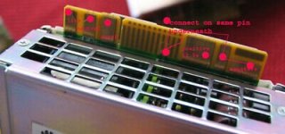
I dismantled some as I need to get the connector piece so that I could have a way of testing them faster without soldering.
There were 2 back connectors strips in each chassis which were the same but only the one was populated.
I cut the one up.Here is a photo of the other.The SMU02B was on the right side.
The ribbon cable would connect to a PCB in the chassis.There was a lot of other stuff in the chassis .I might have a working one still.Here are the photos .


 View attachment 8


There were 2 back connectors strips in each chassis which were the same but only the one was populated.
I cut the one up.Here is a photo of the other.The SMU02B was on the right side.
The ribbon cable would connect to a PCB in the chassis.There was a lot of other stuff in the chassis .I might have a working one still.Here are the photos .
View attachment 8
j bjork
100 kW
rigmo said:HI
Im buy HUAWEI switch power supply R4850G2 53.5V 32A
How to easy get on 48Videal 50Vmin?
Thank you in advance
http://quartermile.ws/slike/
How to get this module if is for ajusment ?
https://www.yleee.com.cn/thread-62600-1-1.html
Were you (or someone else) able to find it or something simular?
I should soon have to modify 2 of these psu:s, it would be nice to be able to adjust them without the programming.
j bjork
100 kW
They are really stuffed inside, and it doesn't look like the picture BotoXbz posted.
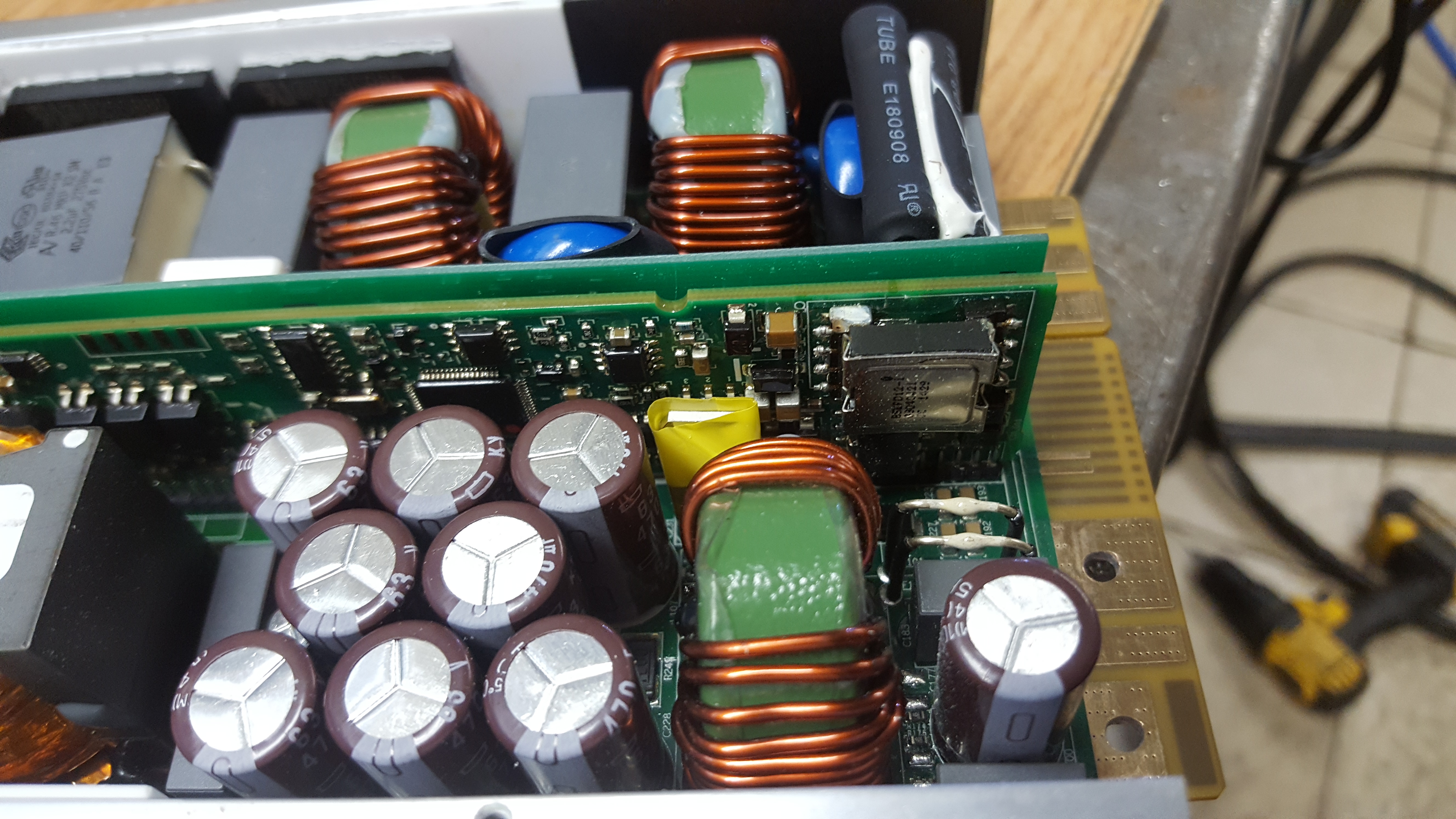
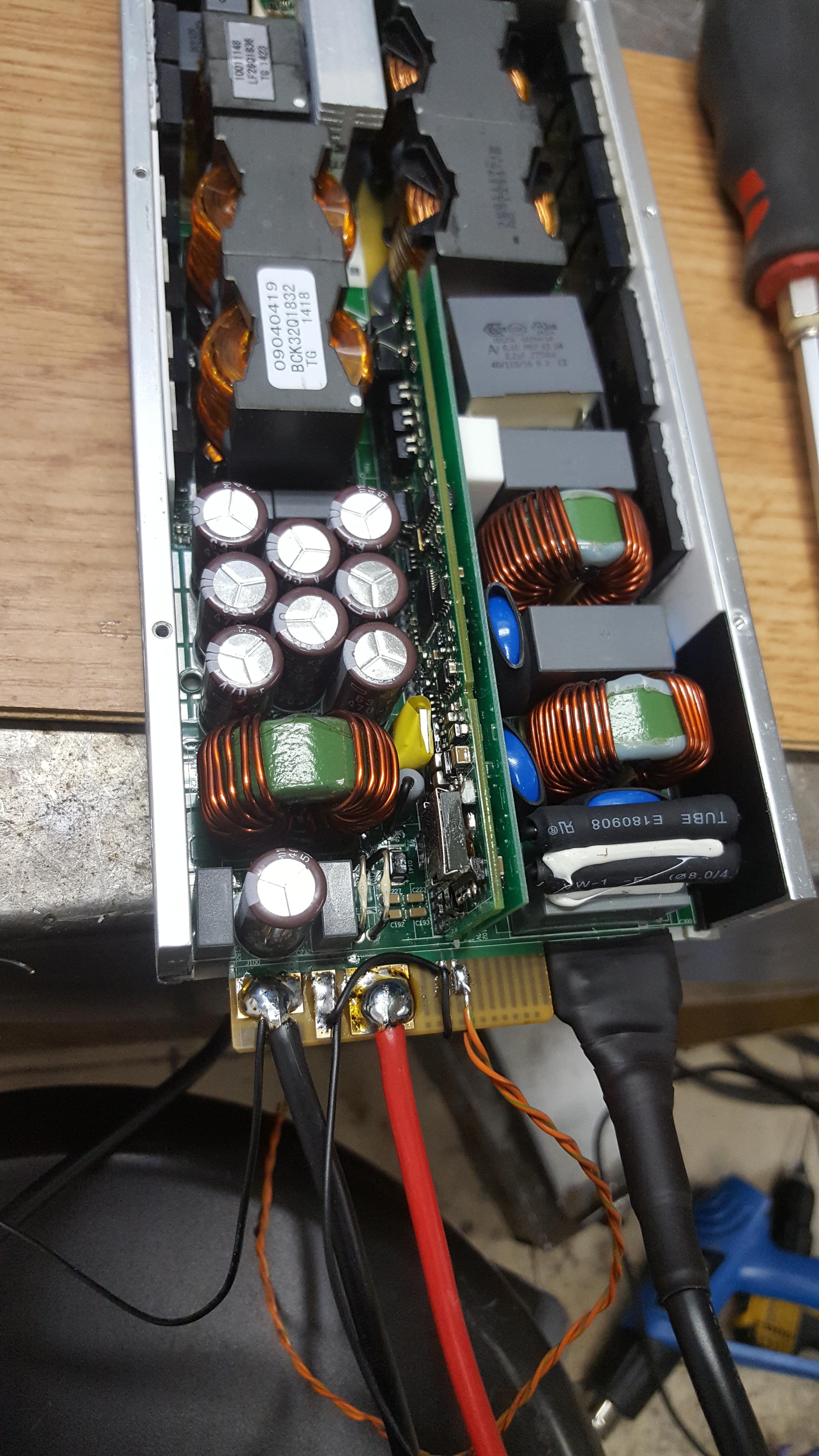
I think I might as well forget about the internal mods, and just go for external connection over can bus.
So, can I get any can-usb adapter and use some sort of program to send code from the computer?
(Yea, you probably get that I am pretty much useless on computers)
I think I might as well forget about the internal mods, and just go for external connection over can bus.
So, can I get any can-usb adapter and use some sort of program to send code from the computer?
(Yea, you probably get that I am pretty much useless on computers)
j bjork said:Were you (or someone else) able to find it or something simular?
I should soon have to modify 2 of these psu:s, it would be nice to be able to adjust them without the programming.
I do not know,,, only china controller.. now I have contact to get it... I have two... no used for now...
https://drive.google.com/file/d/1tu_HWxA4LT2pvY3fkV5aP1W3sTxq9oAj/view
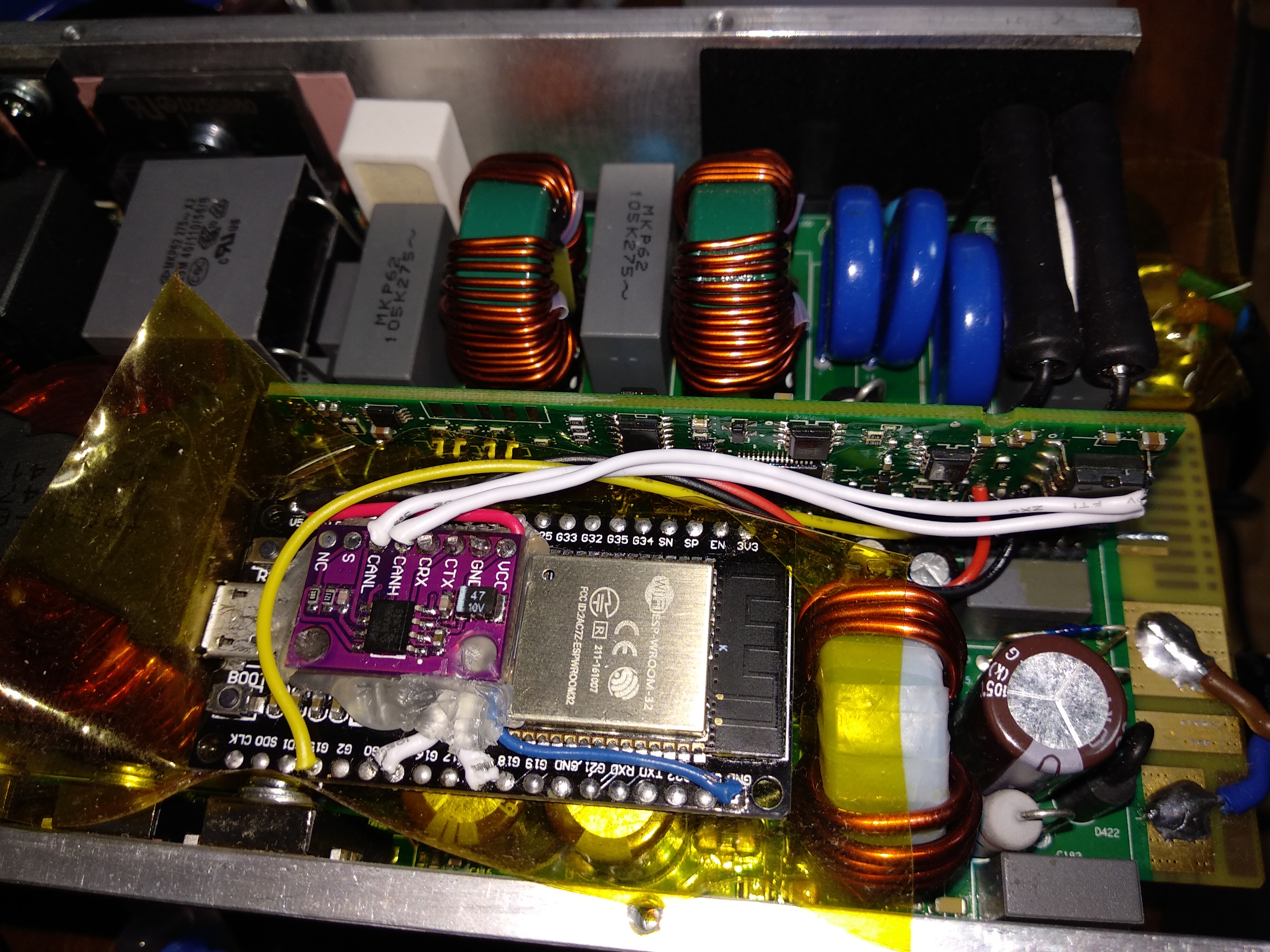
BotoXbz said:A little update on my PSU hacking attempts:
A ESP32 fits nicely inside the PSU, hotglued a TJA1050 onto it.
Power is provided from the PSUs logic board which has a 6.6V source, dropped down to ~5V with two diodes in series.
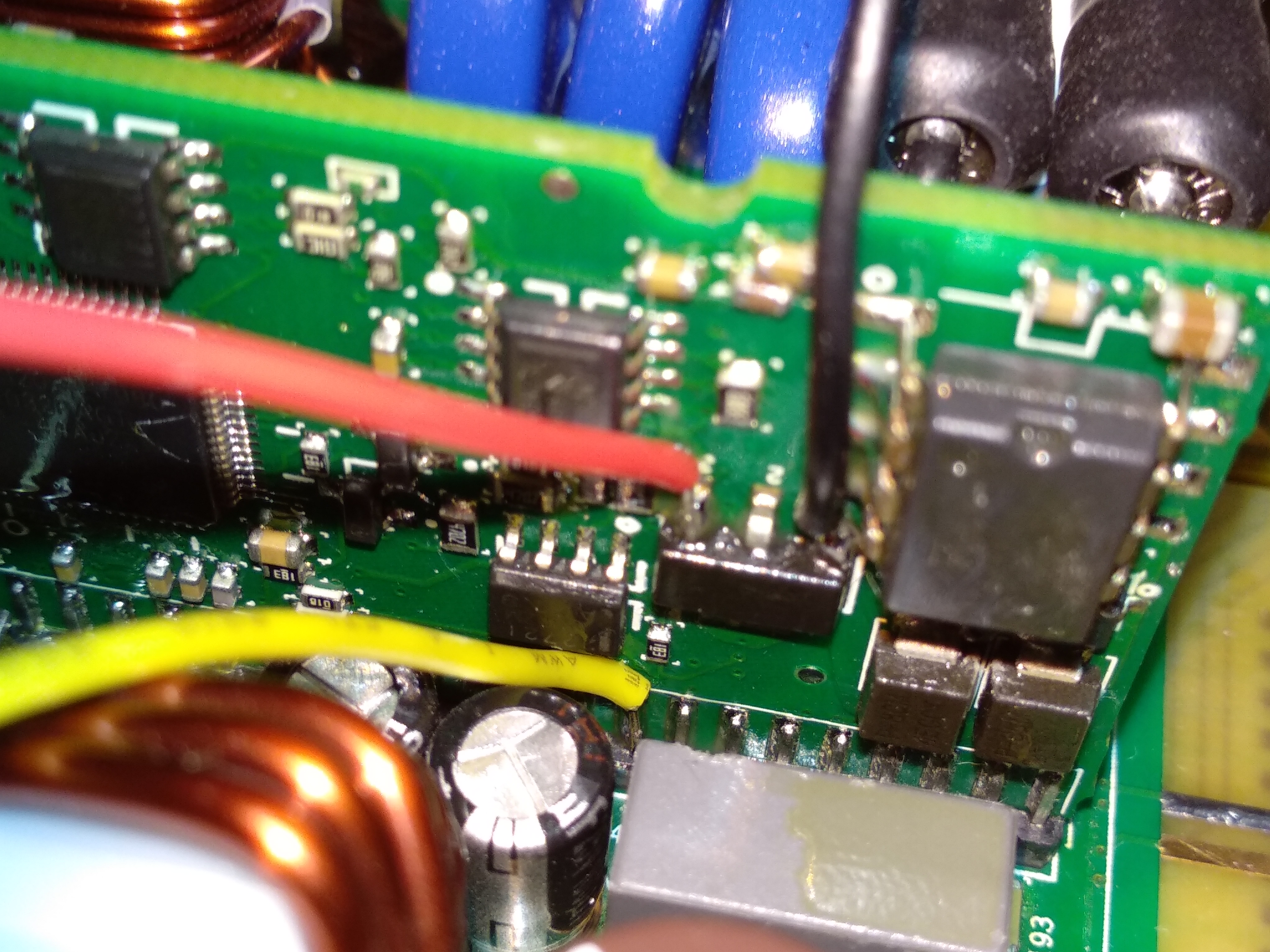
Black = GND
Red = 6.6V
Yellow = 9th pin on the pinheader, Enable pin, pulled up by PSU to 3.3V at 0.1mA
CANL, CANH is on the right side of the chip right next to the black wire.
It's a ISO1050 -> https://www.ti.com/lit/ds/symlink/iso1050.pdf
The ESP32 is always powered when the PSU is powered on, the ESP32 can turn the high power part of the PSU on or off.
I'll probably look into adding a MOSFET as a diode to the output to turn the PSU off when the battery is full, etc.
Work in progress still, code on GitHub https://github.com/BotoX/huawei-r48xx-esp32
Using this lib for CAN on ESP32 https://github.com/sandeepmistry/arduino-CAN
Hi Sir Hi SIr
DO you sale complete PCB for conversion ?
Thank you in advance
BEst REgards