
You are using an out of date browser. It may not display this or other websites correctly.
You should upgrade or use an alternative browser.
You should upgrade or use an alternative browser.
TSDZ2 mid drive with 860C, 850C or SW102 displays only -- Flexible OpenSource firmware (Casainho code only)
- Thread starter casainho
- Start date
e3s said:sign in to github and click on pull request. It's a function to compare changes
 ok,thanks
Hi,
i have some questions about the values ui16_pwm_cycles_counter and ui16_pwm_cycles_counter6
.when motor is near zero speed, the values range are 1----pwm_cycles_counter_max(3125).
when motor is running, the ui16_pwm_cycles_counter range is 1-6????
the ui16_pwm_cycles_counter6 is just 1,no change??
i have some questions about the values ui16_pwm_cycles_counter and ui16_pwm_cycles_counter6
.when motor is near zero speed, the values range are 1----pwm_cycles_counter_max(3125).
when motor is running, the ui16_pwm_cycles_counter range is 1-6????
the ui16_pwm_cycles_counter6 is just 1,no change??
casainho
10 GW
- Joined
- Feb 14, 2011
- Messages
- 6,045
ui16_pwm_cycles_counter counter number of PWM cycles every ERPs and it is reset at every 6 hall sensors transitions.haiyi911 said:Hi,
i have some questions about the values ui16_pwm_cycles_counter and ui16_pwm_cycles_counter6
.when motor is near zero speed, the values range are 1----pwm_cycles_counter_max(3125).
when motor is running, the ui16_pwm_cycles_counter range is 1-6????
the ui16_pwm_cycles_counter6 is just 1,no change??
ui16_pwm_cycles_counter6 counter number of PWM cycles every ERPs/6 and it is reset at every 1 hall sensors transition.
Can you please tell why are you interested on the code?
casainho
10 GW
- Joined
- Feb 14, 2011
- Messages
- 6,045
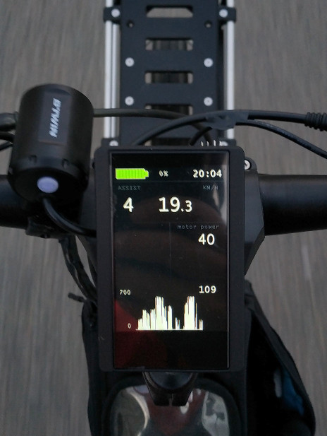
I had for the first time the graph working. On the picture, it shows motor power from last 15 minutes. Max value was 700 W and min value was 0 W. 109 W was the last average value of 3.5 seconds (each line represents the average of 3.5 seconds).The graph misses variable name label.
Next I need to put the graph working 100% and just after I will plug all other variables and find a way for user to change the variable shown on graph, using some key combination.
Maybe the lines of max values can be draw in light red.
Maybe the value on right can be the real time value and shown on the numeric field at top, so if use is seeing the graph, do not need to have the numeric filed for that variable.
Nick said:Should we discuss the feature list of SW102?
What is important data for me:
+ Speed
+ Consumed Wh / Battery bar
+ Current Assist Level
+ Distance traveled (since power on / since reset)
+ Timer (since switched on / actually riding)
+ Basic settings (f.i. I don't need to set max. amount of assist levels and fine tune them).
What I never use and would not miss:
+ Offroad mode switch (As soon as you hack your e-bike you are on the dark side anyway
+ All kinds of range estimation (inaccurate anyway)
+ All shapes of human pedal power "estimation" (inaccurate anyway)
+ Main screen setup (we don't have that much data)
+ Motor Temperature Protection (very complicated to install anyway)
+ Advanced Technical Data (sure important for development but not for "end user")
+ Sure forgot some
I am aware, that this is a highly personal point of view. So please don't beat me
I agree with all of what you wrote, except temperature sensor. I think this is quite usefull to monitor motor temp.
perryscope said:Do you think it may be possible to drill 4 small holes through the plastic cover ( after Remove Up/Dwn key lid) right above the 4 programming pads? Then you could use a standard pin header to connect through to them while programming?
Even if I prefer this over removing the button panel, it seems to me that the pads are at least party below the M button cover. Is this removable ?
If someone want to try, I've use gasoline to unglue laptop battery cases. With any luck, it would also work to unglue this display, thus reducing the risk to damage the plastics. Only a few drops on the seams could suffice.
I used some free time to do some reverse engineering on the SW102 PCBs. I updated the Wiki with my findings:
https://github.com/OpenSource-EBike-firmware/Color_LCD/wiki/Bafang-LCD-SW102
In addition, I created a circuit diagram with the most important pin assignments:
https://github.com/OpenSource-EBike...ob/master/Bafang_LCD_SW102/SW102_nRF51x22.pdf
If someone wants to play around with (or add some feature to) the circuit diagram, here is the Eagle CAD file:
https://github.com/OpenSource-EBike-firmware/Color_LCD/tree/master/Bafang_LCD_SW102
I hope this helps and I hope everything is correct
@casainho
It seems that pin 11 of the flat cable (formerly assigned as +3.3V) is connected to the LCD module pin "RES" which is a reset function. Maybe you can repeat your init code sampling including this pin?
tomjasz
1 GW
For someone completely inept at programming electronics, this is quite overwhelming, At the same time quite exciting since I own a TZDZ2 and have never been happy. I have some rudimentary questions. Should anyone have a few minutes.
Can the TSDZ2 use or is there a version that can utilize BBSxx harness and cables? If yes how is that version identified? It seems there are two versions with different pinout counts?
APT apparently has the TSDZ2 code and can produce the 850C TSDZ2 ready. Has anyone used that setup? How does it compare with open source functions?
Thanks so much for the incredible work. I sent a small donation and will again.
Regards,
Tom
tomjasz said:For someone completely inept at programming electronics, this is quite overwhelming, At the same time quite exciting since I own a TZDZ2 and have never been happy. I have some rudimentary questions. Should anyone have a few minutes.
Can the TSDZ2 use or is there a version that can utilize BBSxx harness and cables? If yes how is that version identified? It seems there are two versions with different pinout counts?
Yes. The 850C version of the TSDZ2 comes with a female 8 pin connector on the controller instead of a male like the standard TSDZ2. This allows the standard Bafang wiring harness for BBSxx to plug right in. In fact, the motor comes with one of these 1T4 8-pin male harnesses. These are being sold by just a few companies right now including Future Bike in Italy http://www.shop.future-bike.it/futurebikeshop/prodotto/display-vertical-per-motore-active-torque-tsdz2/ Eunorau in China, and Electrify Bike Co. in the US (my company). https://www.electrifybike.com/store/p24/TSDZ2.html When running the stock firmware there is no additional functionality other than having a nicer looking display.
To make the open-source firmware more accessible to a wider group of riders without electrical skills, Electrify Bike Co. had a version of the KT-LCD3 manufactured that is plug compatible with the Bafang BBSxx 1T4 harness. https://www.electrifybike.com/store/p114/KT-LCD3_for_TSDZ2_Flexible_OpenSource_%28FOS%29_Firmware_Upgrade.html Since the 850C version of the open-source firmware is not yet available you can start with the KT-LCD3 and then the 850C will just plug in when it is available. (I actually think that the KT-LCD3 will be the long-term preference for many because of its visibility in sunlight and lower cost.)
For those that already have the standard TSDZ2 with an 8-pin male connector, we had a custom 1 to 4 harness with a female connector manufactured in China. https://www.electrifybike.com/store/p116/1_to_4__Female_Cable_for_TSDZ2_FOS_Firmware_Upgrade.html It internally rewires all of the signals to make a standard TSDZ2 to be compatible with Bafang displays and components like throttles and brake sensors. This was a very difficult thing to make happen at low prices so to keep other resellers from having to go through the same thing we have quantity pricing. For 6-pin versions you still have to splice. We have the needed cables and instructions on how to do that.
tomjasz said:APT apparently has the TSDZ2 code and can produce the 850C TSDZ2 ready. Has anyone used that setup? How does it compare with open source functions?
It has no additional functionality other than a nicer display. You need the open source firmware to crank up the functionality.
FYI, Tomjasz, I think we chatted a bit back in my Poweredride days.
eyebyesickle
10 kW
The 850C does have a wattmeter actually - for the TSDZ2 version. FYI - the 850C is actually carried by other companies as well :wink: some had it made a while back and kept quiet
casainho said:
I had for the first time the graph working. On the picture, it shows motor power from last 15 minutes. Max value was 700 W and min value was 0 W. 109 W was the last average value of 3.5 seconds (each line represents the average of 3.5 seconds).The graph misses variable name label.
Next I need to put the graph working 100% and just after I will plug all other variables and find a way for user to change the variable shown on graph, using some key combination.
Maybe the lines of max values can be draw in light red.
Maybe the value on right can be the real time value and shown on the numeric field at top, so if use is seeing the graph, do not need to have the numeric filed for that variable.
Thanks for the update Casainho! The 850C is looking great. Can't wait!
Thanks for the clarification Eyebyesickle. Eco Cycles rocks! Can't wait to see what you do with this stuff!eyebyesickle said:The 850C does have a wattmeter actually - for the TSDZ2 version. FYI - the 850C is actually carried by other companies as well :wink: some had it made a while back and kept quiet
eyebyesickle
10 kW
Rydon said:Thanks for the clarification Eyebyesickle. Eco Cycles rocks! Can't wait to see what you do with this stuff!eyebyesickle said:The 850C does have a wattmeter actually - for the TSDZ2 version. FYI - the 850C is actually carried by other companies as well :wink: some had it made a while back and kept quiet
Ha, I'm just busting balls over here! Seriously though, I can't wait to see how casianho and the rest of the team progress with the work with the TSDZ2 and the 850c, SW102, etc... It's really nice to see people come/work together for a common goal and share the info like this. You don't get that many places nowadays!
I got a few 850c displays and controllers waiting to burn up if they have to testing this new version
I'm finally about back to decent riding shape just in time for the seasoncasainho
10 GW
- Joined
- Feb 14, 2011
- Messages
- 6,045
Very good work!! Wiki now misses an image of and a link to the schematic.Nick said:I used some free time to do some reverse engineering on the SW102 PCBs. I updated the Wiki with my findings:
https://github.com/OpenSource-EBike-firmware/Color_LCD/wiki/Bafang-LCD-SW102
In addition, I created a circuit diagram with the most important pin assignments:
https://github.com/OpenSource-EBike...ob/master/Bafang_LCD_SW102/SW102_nRF51x22.pdf
If someone wants to play around with (or add some feature to) the circuit diagram, here is the Eagle CAD file:
https://github.com/OpenSource-EBike-firmware/Color_LCD/tree/master/Bafang_LCD_SW102
I hope this helps and I hope everything is correct
@casainho
It seems that pin 11 of the flat cable (formerly assigned as +3.3V) is connected to the LCD module pin "RES" which is a reset function. Maybe you can repeat your init code sampling including this pin?
I am not working on SW102 now. I think is up to you to try initialize the LCD
Unfortunately, I did not log the LCD RESET pin with the logic analyzer but I would look at the other libs you pointed before and find how reset should work...
Hi
I'm planning to order a kit using the tsdz2 and installing the custom firmware at some point.
Should I get the 36, 48, or 52v kit if cost is about the same and why?
I'm thinking that it is easier to source parts for the 48v kit, as that is much more common, but I would think that the 52v should run cooler, but how much?
Is there any actual hardware difference between the 48 and 52v versions?
casainho
10 GW
- Joined
- Feb 14, 2011
- Messages
- 6,045
This seems a popular question of new users and because of that I created an entry on the FAQ to answer this -- please read the TSDZ2 FAQ.cnrd said:Hi
I'm planning to order a kit using the tsdz2 and installing the custom firmware at some point.
Should I get the 36, 48, or 52v kit if cost is about the same and why?
I'm thinking that it is easier to source parts for the 48v kit, as that is much more common, but I would think that the 52v should run cooler, but how much?
Is there any actual hardware difference between the 48 and 52v versions?
Dear All,
Need some help,
Looks like the firmware on my motor got wiped or corrupted (see post : https://endless-sphere.com/forums/viewtopic.php?f=30&t=98281&p=1458628#p1458628)
I'm on holiday in Spain and forgot to bring my ST programmer and cable (shame on me )
)
Is there somebody in the wide area (150km) of Cambrils or next week Valencia (both Spain) that could help me out with a oneTime usage of a ST programmer and connector cable to save my mountainbike holiday ?
(bottle of Cava or Vermut or Spanish Gin would be given with pleasure )
)
Need some help,
Looks like the firmware on my motor got wiped or corrupted (see post : https://endless-sphere.com/forums/viewtopic.php?f=30&t=98281&p=1458628#p1458628)
I'm on holiday in Spain and forgot to bring my ST programmer and cable (shame on me
Is there somebody in the wide area (150km) of Cambrils or next week Valencia (both Spain) that could help me out with a oneTime usage of a ST programmer and connector cable to save my mountainbike holiday ?
(bottle of Cava or Vermut or Spanish Gin would be given with pleasure
casainho
10 GW
- Joined
- Feb 14, 2011
- Messages
- 6,045
I think is unlikely the firmware got corrupted.Zelenaar said:Dear All,
Need some help,
Looks like the firmware on my motor got wiped or corrupted (see post : https://endless-sphere.com/forums/viewtopic.php?f=30&t=98281&p=1458628#p1458628)
I'm on holiday in Spain and forgot to bring my ST programmer and cable (shame on me
Is there somebody in the wide area (150km) of Cambrils or next week Valencia (both Spain) that could help me out with a oneTime usage of a ST programmer and connector cable to save my mountainbike holiday ?
(bottle of Cava or Vermut or Spanish Gin would be given with pleasure
Since that happened after touching the motor, and if LCD does not show any variable change, I would say the issue can be on the cables, like UART wires to LCD being wrong wired or such.
An LCD3 would help a lot to debug on this situation.
Also make sure the motor is turned on, that again is the LCD that does that but the wires must be correctly connected/wired.
casainho said:I think is unlikely the firmware got corrupted.Zelenaar said:Dear All,
Need some help,
Looks like the firmware on my motor got wiped or corrupted (see post : https://endless-sphere.com/forums/viewtopic.php?f=30&t=98281&p=1458628#p1458628)
I'm on holiday in Spain and forgot to bring my ST programmer and cable (shame on me
Is there somebody in the wide area (150km) of Cambrils or next week Valencia (both Spain) that could help me out with a oneTime usage of a ST programmer and connector cable to save my mountainbike holiday ?
(bottle of Cava or Vermut or Spanish Gin would be given with pleasure
Since that happened after touching the motor, and if LCD does not show any variable change, I would say the issue can be on the cables, like UART wires to LCD being wrong wired or such.
An LCD3 would help a lot to debug on this situation.
Also make sure the motor is turned on, that again is the LCD that does that but the wires must be correctly connected/wired.
Hi casainho,
First of all a big tnx to you (and the others) for all the efforts done to bring this firmware to the openSource world.
(being myself a IT guy I realise very much how many free time this 'eats' )
Everything was working before with the same wiring and I don't think they touched in the bikeshop the cables towards display or motor. They only had to work on the cables of the diskbrakes .
I tripple checked the connectors and couldn't find any bended connector pin. The only small possibility would be that they touched the cables at the display side. I will open the lcd display and check.
How can I test if there is communication between display and motor ?
Unfortually my LCD3 display is also at home (as I didn't yet wired it correctly), that's why I'm using the qMarco firmware ...
casainho
10 GW
- Joined
- Feb 14, 2011
- Messages
- 6,045
The LCD works stand alone from the motor. If the data variables for configuration does not arrive to the motor, it may not work. Like, if it consider 0 assist level after power on and LCD do not send assist higher than 0, then motor will not assist.Zelenaar said:How can I test if there is communication between display and motor ?
But if you had communication, the battery voltage would be correct to what you expect. I don't know what that LCD shows when it does not receive any battery voltage after power on.
What if you had incorrect configuration on battery cells number??
Or most important, are you sure motor is turned on?? Because LCD does but motor may not be turned on and so no data on LCD!!
casainho said:This seems a popular question of new users and because of that I created an entry on the FAQ to answer this -- please read the TSDZ2 FAQ.
Ah thanks, must have missed it
so that means I can just order a 48v model and then decide on the voltage later.tomjasz
1 GW
Rydon said:Thanks for the update Casainho! The 850C is looking great. Can't wait!
A fellow from TS tells me that APT can produce the 850C with the proper firmware.
tomjasz said:Rydon said:Thanks for the update Casainho! The 850C is looking great. Can't wait!
A fellow from TS tells me that APT can produce the 850C with the proper firmware.
That is a version of 850C for the stock firmware. It won't work with the open source firmware. The version Casainho is working on will have many times the functionality of the one from APT. It will also have real-time graphing of selectable data streams. Truly awesome.
casainho said:The LCD works stand alone from the motor. If the data variables for configuration does not arrive to the motor, it may not work. Like, if it consider 0 assist level after power on and LCD do not send assist higher than 0, then motor will not assist.Zelenaar said:How can I test if there is communication between display and motor ?
But if you had communication, the battery voltage would be correct to what you expect. I don't know what that LCD shows when it does not receive any battery voltage after power on.
What if you had incorrect configuration on battery cells number??
Or most important, are you sure motor is turned on?? Because LCD does but motor may not be turned on and so no data on LCD!!
Hi Casainho
I disassembled the motor/controller and did some testings and measurements
Battery (unplugged, switched on) : 41.7v
Controller (battery on, display on)
Controller 5wire white connector :
- Black-red : 4.2v (0v when display off)
- Black-green : 4.8v (0v when display off)
- All other combinations : 0v
Controller 2 wire white connector :
- Black-red 0v
Motor :
- All combinations between blue-green-yellow 0v
Motor to display connector (6p female):
(Unplugged from display, battery on)
- Black-green : 41.3v
- Black-all others : 0v
Motor to speedsensor/program connector (6p male)
(Unplugged from speedsensor, battery on, display on)
- Orange-black : 4.6v
- Orange-brown : 4.9v
- Orange-purple : 2.1v
Display :
Disassembled and checked connections
After powerup (using (|) button) : Battery indicator always on 1bar, level up/down working but no reaction of motor, walk assist not working.
Odo correct on 144km

--------------------------------------------------------------------
What to conclude ??
- Wiring issue ? : I don't think so
triple checked as much as possible the wiring/connectors.
was working before, nothing changed myself, no indications something was touched in the bikeshop during disc repair
- Display issue ? : Maybe ?
Is the display still sending correct signals to motor to ie power up ? (But I can see 4.2v & 4.8v on the 5pwhite connector in the controller when display is powered on)
not sure how to test more
- Controller issue ? : Maybe ?
not sure how to test more
- Firmware issue ? : Maybe ?
Corrupted or wiped ? not sure as I can't test without ST-link programmer
Similar threads
- Replies
- 4
- Views
- 923
- Replies
- 1
- Views
- 506
- Replies
- 207
- Views
- 26,786
- Replies
- 2,431
- Views
- 205,081
- Replies
- 0
- Views
- 660