Controller suggestions??

I'm using a sensorless heinzmann PMS 80 motor.
I'll double check the ignition wiring tomorrow. I had just connected the two wires to each other with a switch instead of connecting them to a power source. The CycleAnalyst powered up when they were joined together though.
 
Well my frustration level is growing...
Nothing I have tried seems to make any difference.
Still no life from this motor/controller setup.
I also find it troubling that the controller didn't come with a scrap of documentation.
Just a controller with a scuff mark on the case in a mailer envelope.
On top of that, I told PV that I wanted to be able to carry up to 40amps with this setup yet the main power wires appear to be only 12 gauge.
That's pretty sketchy for that kind of power in my estimation.
I'm rapidly losing patience with this process and may be returning this controller.
 
Did you order the 12F dual mode controller? You need the dual mode controller to use the PV controller for a sensorless motor. I spent the extra $20 to get the PV 12F dual mode controller incase I ever smoke a Hall Sensor and need to get home 😁
 
Archer321 said:
On top of that, I told PV that I wanted to be able to carry up to 40amps with this setup yet the main power wires appear to be only 12 gauge.
That's pretty sketchy for that kind of power in my estimation.

Sketchy or not, it's pretty normal. Those leads are short. They work fine for the same reason that the power traces on the controller PCB work fine, even though those are much smaller than your preferred wire gauge.

Check the enable leads to see if one of them has voltage on it and the other doesn't. If not, then they're definitely not intended to switch to each other. Many of the cheap generic controllers I have used have a single enable wire that connects to the positive lead.
 
Talon said:
Did you order the 12F dual mode controller? You need the dual mode controller to use the PV controller for a sensorless motor. I spent the extra $20 to get the PV 12F dual mode controller incase I ever smoke a Hall Sensor and need to get home 😁

Yes I did, specify sensorless but honestly I'm not sure what I actually got as there was zero documentation with it.
He also asked me twice what voltage I was planning on running and twice I told him I wanted the flexibility to use anything between 36v and 60v.
Yet after I received the controller and was asking about why I couldn't it to run he tells me he set it up for 48v because "that's what I specified". So since then I have been trying it on 48v.

The "ignition" connector contains two small wires, one red, and one orange. The red has battery voltage on it and the orange has nothing. When I jump them together my CycleAnalyst powers up but nothing else happens.
 
GGSN Thumb Throttle Speed Control... https://www.amazon.com/dp/B07PN3LQK1?ref=ppx_pop_mob_ap_share

Cheapie hall sensor throttle is what l'm using now.
Initially I was trying a 5k resistor.
 
Archer321 said:
...Initially I was trying a 5k resistor...

Not understanding -- do you mean just a 5k resistor as a proxy for a wide-open throttle?

NOTE: The key thing for the PV throttle (wired directly as you are doing) is to be sure to limit the voltage to a range of 0.8-3.6V. Most cheap Chinese throttles are good to go in this respect as opposed to Magura/Domino types of throttles that use a range of 0-5V.

Could you verify that the voltage coming out of your throttle is 3.6V max?
Also, I assume you haven't bothered yet with the EBS- EBS+ connectors -- correct?

M

P.S. FWIW, my PV didn't come with any instructions either -- but I got it to fire up the very first time, so I'm concerned that your unit is either defective or has become defective during these various trials.
 
I started with a Magura throttle which is a 5k ohm potentiometer. I used a voltmeter to verify that the signal voltage on the green throttle wire ran between .8v and 3.6v.

I have not done anything with the EBS wires.
 
Out of curiosity (or desperation) does this controller care what the phase winding resistances are?
I'm not sure what motors it was intended for, but my motor has .4 ohm resistance across any two of the phase windings.
I have successfully run this motor off a 12v RC ESC before so I know it works.
 
Sorry for your frustration, but is the motor good? I mean, you got it cheap which makes me wonder if the motor works at all?

:D :bolt:
 
As I said earlier today... Yes, I know the motor is good. I have run it off of a 12v radio control ESC.
I did it again today too.

The real question about the motors this controller has been used on is about what their phase winding resistance is. I suppose I could Google those motors and see if their resistance has been specified...
 
Archer321 said:
As I said earlier today... Yes, I know the motor is good. I have run it off of a 12v radio control ESC.
I did it again today too.......

Ok, then lets try to reverse engineer this. What esc did you use? Manuacture, model, ect?

:D :bolt:
 
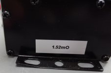
IMG_20190420_213736119~2-1376x912.jpg

So this is the sticker on the controller.
I have to assume this is in reference to winding resistance.
When I googled the specs of the Mxus 3000 it showed 4 versions with winding resistances between .07 ohms and .225 ohms. So with this motors resistance coming in at .4 ohms is that the problem?

The RC ESC I used is a Hobbyking 30amp.
I don't have the model number right now as it's out in my shop.
 
IMO your problem doesn't have to do with winding resistance. When you get the time, post the make and model number. Also, glad you are now posting pictures. That will help.

:D :bolt:
 
The 1.52 mOhm is the current shunt resistance. This is the value you dial into a CA to get accurate current readings. It should work fine with that motor.

I'm guessing the controller is default programmed for sensored mode and that's why your motor won't run. Just for fun you might try manually spinning the motor then hit the throttle. If it's going fast enough for the sensorless detection, it might start running.
 
Ok. Well you cleared up the mystery of the sticker then.
I have already tried spinning the motor to see if it would start but I couldn't get it going very fast with just a bare shaft.

Talon, have you ever tried unplugging your hall sensors to try it as sensorless?
 
I know that you have an controller now, but I would like to suggest the original VESC 4.12 (12s max safe, ~$60 on ebay). It might not be able to sustain your power requirement without cooling mods though.
Then there is the new Vesc six (~$250) that handles 80A continuous.
The best part is that they are open source and the Vesc Tool is excellent.
I have no affiliation with them but I do use them in a couple of bikes and really like them.
 
thewho said:
I know that you have an controller now, but I would like to suggest the original VESC 4.12 (12s max safe, ~$60 on ebay). It might not be able to sustain your power requirement without cooling mods though.
Then there is the new Vesc six (~$250) that handles 80A continuous.
The best part is that they are open source and the Vesc Tool is excellent.
I have no affiliation with them but I do use them in a couple of bikes and really like them.

Well if this PV controller continues to be a problem, I'll be sure to check it out.
Thanks
 
How about a picture of your esc and motor wiring.

:D :bolt:
 
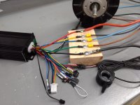
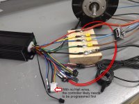
IMG_20190421_182838936-1152x864.jpg
This is what I'm working with.
You can see the jumper wire on the ignition circuit.
Power is 48v.
 
Archer321 said:
You can see the jumper wire on the ignition circuit.

And as has been stated previously, that is 100% incorrect.
You need to wire BOTH the orange and the red "ignition" wires to a (switched) 48V source -- i.e. MUST match whatever battery voltage you are using.

M
 
MJSfoto1956 said:
Archer321 said:
You can see the jumper wire on the ignition circuit.

And as has been stated previously, that is 100% incorrect.
You need to wire BOTH the orange and the red "ignition" wires to a (switched) 48V source.

M
I tried that too.
No difference.
Besides, as the red wire has battery voltage on it already, what would change?
 
Archer321 said:
I tried that too.
No difference.
Besides, as the red wire has battery voltage on it already, what would change?

Um, the MCU is powered by the orange wire. So basically nothing will happen if either the orange or red "ignition" wires are not both powered by your (switched) battery voltage. Why do you doubt us?

M

P.S. for those needing a little hand-holding, the wiring should look more like this:

redo PV wiring for IYI.jpg
 
Back
Top