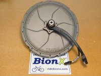
BionX, want help connecting up this motor

lithail

100 mW
Joined
Apr 24, 2019
Messages
35
Hello,

I have just purchased a bionx motor that had been bought from the factory when it shut down. I am wondering if someone could help me figure out the wiring as I only bought the motor with no harness but the speed controller is built in. I also dont know what voltage it is.

If anyone knows about these motors could you please help me. I could not resist the price of it. Also I was told there is a way to unlock the speed?

If I can't figure out how to use it as is, I will use an external controller as I saw a youtube video showing how to do it.
I will up load some pics.
View attachment 1s-l1600.jpg
Thanks in advance
 
You'll also need a Bionx battery and console to make this motor work "the way it's intended". These components communicate with each other via CANBUS and the controller inside your motor won't do anything without this communication.

Your only alternative is to open it up and use an external controller, but IMO it would be a shame to gut such a nice looking brand new motor.
 
1N4001 is absolutely right - you have two (three...) choices:

1) Go with proprietary "BionX" system/parts:
======================================
a) spend a ton more $$ to get a very proprietary and relatively new/fresh BionX 48V battery pack, making absolutely sure that its internal BMS is fully functional.
b) hope to get lucky and get a compatible (BionX OEM) display, wiring, and controls (optional throttle, ebrakes, etc.) without spending even more of your precious $$. The reason I say "lucky" is because you won't be able to easily verify if any of your parts being acquired work as intended until you have them all put together -- and if the system *then* doesn't work, you likely won't have duplicate parts to help you debug the system.
c) search this ES forum for "BionX", and allocate at least 50-100 hours of intense study so that points a) and b) above start making sense to you. During your studies you'll encounter names like "cephalotus" and "syonyk" and others who know way more about this I ever hope to.

2) Convert your newly acquired BionX motor...
=======================================
... into a pretty decent 'generic' direct drive BLDC motor, either using the existing three Hall sensors or not, and either using the built in torque sensor (strain gauge) or not. Unless you have some decent shop skills and tools (like harmonic balance pullers, c-clamps, rubber mallet, etc.), this might amount to something of a challenge in itself, although it is in fact doable. You'll end up opening the motor, removing the internal proprietary BionX controller board, and -- at the very least -- bringing out the three phase wires and connecting them to your (new) external controller, which in this case would need to be able to run the motor in 'sensorless' (i.e., no Halls) mode.

You could of course also bring out five additional wires and utilize the original Hall sensors. Two additional wires are needed to give you access to the single 350 ohm strain gauge glued to the stator shaft on the drive side of the motor. Where and how you pick up and amplify the gauge's output will be its own fun project. If you were to use all of these functions in the motor, you'd be bringing 10 wires out of the motor through a space not designed for that volume. I'm still working on that, so I don't know what to tell you (yet).

Justin (at ebikes.ca) says that this little 350 watt motor, when converted like this, and has Statorade added to help with cooling, makes a pretty decent DD hub motor, and I take him at his word for this.

Optional 3) Cut your losses.
a) use it as a paperweight -- as 14001 says, it's a good looking, newish motor, and the weight is about right to keep most papers from flying away.
b) ???
c) Welcome to ES, everything you need to know is here! :D
 
Thank you for a very much appreciated detail description.

I am a licensed small engine mechanic. So I enjoy taking things apart. If i don't have the tools I need I just make them.

I have been doing research and watching video's. I have decided to take it apart and use an external controller. I will bring the 3 phase wires out and the hall sensor wires.
I don't know what the torque sensor (Strain Gauge) does?
Is it important to performance?

I hope to start this rebuild Monday 29 April 2019. I will try to document as I go but sometimes I get so into working I forget to even take pictures.

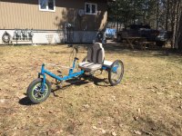
I also custom built this trike but I would like to make another one because my wife and I fight over who is going to ride it. the front wheel is a rear hub motor from an EMMO Hornet.

IMG_3319 (Copy) (Copy).JPG

Thanks again for the info.
 
That's a clean looking build. Does the Emmo motor have its controller built in, or came along with the hub?

It sounds like you luckily will have some company, working on adapting an alternative controller to the Bionx. That involves a lot of know how that I don't know how. The strain gauge is for pedal assist - the controller can feel you trying to push with the pedals, as an alternative to throttle input. Obviously that assumes the pedal drive is connected to the hub axle, which is not the case with your Emmo motor there. I've never really understood why people get so "cranked up" about pedal assist, personally - for me, a good throttle setup is very flexible and easy to use. A controller with a "cruise control" function helps a lot. But a lot of people love their pedal assist, and a torque based system seems to be much more desirable than the "cadence" system that senses crank motion.

What does it take to get "regen" out of a Bionx + alternate controller system? Are the phase wires enough?
 
donn said:
I've never really understood why people get so "cranked up" about pedal assist, personally - for me, a good throttle setup is very flexible and easy to use.
Lots of reasons, but the most common are legal compliance, keeping hands free to do other things, hand problems (like me), or simply the feel of bicycling by controlling the power with your legs (bionic legs, hence...bionx ;) ).

In my case, cruise control isn't useful, as there are constant speed changes due to traffic or conditions (traffic controls, road surfaces, etc), for most of my rides, and my hands randomly go numb so I can't really tell what I'm doing with a throttle when it happens, and have to keep a close eye on speedometer/etc taking attention away from the road and other traffic/etc. PAS lets me use my otherwise-barely-useful legs to "pedal" the trike or bike like I used to. Full torque control would be better than cadence, for me if the CA3 would let me do that; though cadence is good enough for some people.

What does it take to get "regen" out of a Bionx + alternate controller system? Are the phase wires enough?
It's just like any other DD hub if using an external controller. PHase wries only if you're using sensorless, but you'll also need the hall wires if you use a sensored controller.
 
The emmo motor has an external controller.

It’s 48v 500w. The trike as a solid real axle that the rider can pedal. The problem with this build is that while turning one wheel drags because of the solid rear axle.

I have a new design in my head that will eliminate that problem. I am currently just searching for 2 identical bikes for free. For the next build.

I will post pictures of the Bionx when I split it.
 
@Rowbiker

Do you think you could use a Ethernet type cable for the hall sensor and pedal assist or would it but to small of a wire?

On the trike I built I currently am using a Ethernet cable for the hall sensors . I didn’t know what the wires did when I built the trike but I knew I needed them so I just used the cable I had. It was good because it’s a small cable but has a lot of small wires in it.
 
As long as you don't have to run the wires along a route that gets flexed a lot, ethernet wire is perfect. There's almost no current going through this system, so even 30AWG would probably be enough, even on a 'longish' bike like yours. The high twist factor of even Cat3 ethernet will help reduce noise (EMI or RFI), which can be a gremlin causing issue. I usually end up using high-strand count silicone insulated wire because my prototypes require a lot of flexing in parts of their geometry, and solid copper of any kind fatigues and breaks. Recycled printer and modem cables also can be useful for this.

The torque sensor (strain gauge) is simply a very finely egineered resistor (at 350 nominal ohms). The two small white wires you'll find when you open the motor are very small, and polarity doesn't matter. This sensor gave BionX a very distinct advantage in the ebike market segment using hubmotors because it provided the typical rider with a very pleasant-feeling assisted ride. Most people with BionX experience (myself included) have positive things to say about this part of the system. The challenge you'll have if you choose to use this sensor in your system includes the following issues:
1) as stated in a previous reply, you must have the rider's physical effort (pedaling, or in my case, "rowing") be connected to the drive side of the motor's axle. This usually means a chain over a freewheel or a freehub cassette. If your BionX motor is newish, this is most likely a freehub. In use, you must make absolutely certain that the milled flat on the axle (to which the strain gauge is glued) is perpendicular to the 'chain line'. This is so that any pull on the chain causes the most deflection of the axle, which is what the strain gauge measures. Without this logical/physical relationship, there is no possibility of getting any meaningful assist relative to the rider's efforts.
2) The change in resistance of the strain gauge, as the axle flexes, is very small. You can get the details easily from online sources if you choose to go this route. The main point is that you typically provide the strain gauge with an 'excitation' current at around 5-10 volts, but you'll see a variation of only several millivolts as the rider stomps on the pedals. No 'standard' off-the-shelf controller that I know of is equipped to deal with this millivolt input, so you'll have to find a way of converting this tiny signal into a 1-4 volt range that controllers like to see (think "throttle" input here). Google "instrumentation amplifiers" and go down that rabbit hole for a while.
3) This was all handled on the internal controller you're about to remove, and I've not been able to crack the (unavailable to me) schematics of the BionX controller on how they did this. If I were a BionX engineer, I'd have taken the input from the strain gauge and fed it into a Wheatstone bridge configuration and amplified/conditioned the signal to be in parallel with the throttle logic. This is all pure speculation on my part, and I'm no EE. This is likely to be a challenge, but I really love the feeling of a well-tuned torque assist e-vehicle, so I decided to go down that path about six years ago and haven't regretted a minute of it.
4) Don't throw away the internal controller -- if it's from a new motor, there's likely a market for it since these parts typically fail long before the motor itself fails. Who knows, you might even get a 'free' motor out of the deal!

Do take pictures, even of failures, since we *love* watching other people work! Best of luck going forward.
 
TBH its a 250W, so quite useless in many respects (to me) except for a very light pedal assist bike that will gently help (to you).
 
markz said:
TBH its a 250W, so quite useless in many respects (to me) except for a very light pedal assist bike that will gently help (to you).

I believe from what I have read is that if you use an external controller you can get more wattage out of this motor. But I could be wrong. I read that Bionx used a lot of the same motors but limited them with controllers. So a 250 would be the same as a 500w. But limited by the 250w controller.
 
Yes, you could but its proprietary. Someone could use it if you were to sell it. Then you could just buy a generic kit and use whatever controller you want. YESCOMUSA is cheap.
 
Once he's replaced the controller, he's out of the woods on the proprietary issue, it's just another direct drive hub motor. I wonder how far you can really push those things - probably more than 500W, at least for short bursts? Assuming 48V, it's easy to end up with a battery and controller that will do 20A, which is closer to 1000W. Would you configure the controller to clamp it down to 500W absolute limit, or try it out at full power and see if it starts to smoke?
 
lithail said:
It’s 48v 500w. The trike as a solid real axle that the rider can pedal. The problem with this build is that while turning one wheel drags because of the solid rear axle.

I have a new design in my head that will eliminate that problem. I am currently just searching for 2 identical bikes for free. For the next build.
What specifically is your idea? I've worked out quite a few trike designs from recycled parts, though I've only built three, so I can probably help you work out what will do what you want. If this motor is for that trike, then you might as well post it here and make this a build thread. Otherwise you can always start a new thread and link it here for the build. :)

Regarding cabling, rather than teh solid-conductor ethernet cable, you might look at USB, Firewire, or other similar cables to repurpose. Firewire has at least six (up to 10!) conductors in a typical cable for the large style connector. USB has at least five conductors. I think some of the LightningPort apple cables have at least seven, possibly more (one I have here, found on roadside with broken end, uses eight), some may only have five. All of these cables are pretty small diameter, and use pretty fine wires in them--but there's virtually no current in any of these data lines, so that doesn't matter. Even nicer, these all have shields, to help keep from inducing noise into the wires from the motor/etc.


Old serial cables often have five to eight (or more) conductors, and may also be shielded, but are often larger diameter. AT-style, or PS/2-style, keyboard cables sometimes ahve up to eight conductors (even though they only use 4-5).


If you use extension cable versions of any of hte above, you also get a free pre-installed connector, so you don't have to add one to your cable (to allow removal of motor from system). Just cut the extension at the point that gives you enough wire to run into the motor, and use the other part to wire to your contorller/etc. To waterproof this connector, fill it with vaseline or actual dielectric compound (battery terminal grease), put a piece of heatshrink over one, plug them together, slide the shrink over, fill the shrink with vaseline or other dielectric compound, then apply heat to shrink it over the connectors. It will then both secure them together, and keep water out. Easy to cut to disconnect when you need to. ;)
 
rowbiker said:
2) The change in resistance of the strain gauge, as the axle flexes, is very small. You can get the details easily from online sources if you choose to go this route. The main point is that you typically provide the strain gauge with an 'excitation' current at around 5-10 volts, but you'll see a variation of only several millivolts as the rider stomps on the pedals. No 'standard' off-the-shelf controller that I know of is equipped to deal with this millivolt input, so you'll have to find a way of converting this tiny signal into a 1-4 volt range that controllers like to see (think "throttle" input here). Google "instrumentation amplifiers" and go down that rabbit hole for a while.
Better yet, look up Justin_LE's posts for his skateboard project (and other stuff) that uses strain gauges, and see what he used. He may even have something that lets the CA use it as a torque sensor for PAS, along with standard cadence sensor on the cranks.
 
donn said:
Once he's replaced the controller, he's out of the woods on the proprietary issue, it's just another direct drive hub motor. I wonder how far you can really push those things - probably more than 500W, at least for short bursts? Assuming 48V, it's easy to end up with a battery and controller that will do 20A, which is closer to 1000W. Would you configure the controller to clamp it down to 500W absolute limit, or try it out at full power and see if it starts to smoke?

I like to push the limits I am going to start with a 1000w controller lol
 
So you have bought a nice and perfectly fine BionX motor?

After removing the electronics you will tun it into just some motor. Imho that's a option for the old PL and SL motors with freewheel mount, there are x-thousands of them available and freewheel is outdated anyway and doesn't harm you so much if you head for an electric motorcycle instead of a motor assisted bike.

If you have a new and working BionX motor with cassette mount I think it is sad to turn a quite expensive motor with limited supply which has one of the best pedal assist systems available anywhere into just a cheap motor like many others. Removing the 48V 30A controller and the sensoric is like removing 300-400 USD from the motor in my opinion.

If you want to make an electric bike you are better with the big heavy Chinese motors, but if you want a pedal assist system with recuperation I would recommend to stay in the BionX world. It will turn out much more expensive if you would to it with Chinese components.

The most critical and expensive part in teh BionX world besides the motor is the battery.

There are several options:

1. Buy a genuine BionX 37V or 48V battery. 37V is limited to G2 systems only.
2. Only buy the genuine BionX BMS from someone who doesn't sell you the defective junk. The 3/V or 41V (comapny: Trek) BionX BMS is very easy to use, there are only 3 connections to the battery: + and - and 10kOhm NTC to -
Maximum speed is not as high and you are limited to the G1 and G2 controller versions
The 48V BionX is more complicated and needs 4 temperature sensors and a 13s balancer connection, so it is wiser to keep it connected to the battery pack. With older software Ver 111 and hardware 6.2 or lower you can remove the balancer cables. No individual cell "protection" than.
3. Try to use BionX without a genuine BionX battery. Someone build his own BionX BMS that is cmpatible to G2 and RC3:
https://www.pedelecforum.de/forum/index.php?threads/auch-bionx-gmbh-vor-dem-aus.59897/#post-1110690
It is said that it is much easier to do that with RC3 instead of G2, because the RC3 protocoll is more stringend and the motore (drive) is the master of all things, all other BionX components are just stupid slaves.
You may ask him for more details
There is also a no BMS at all solution available for BionX:
https://endless-sphere.com/forums/viewtopic.php?f=3&t=93078&start=100#p1372652
It works with G2, I#m not sure if it works with RC3, too.
4. A hybrid solution. Buy a 22V, 26V, 37V (or 48V) BionX BMS. Connect it to a voltage within its working range from a betryr pack or DC-DC system. Connect the motor to a voltage you like, AFAIR you need connect mass.
You will find more information here: https://www.pedelecforum.de/forum/index.php?threads/bionx-52v-extender-14s4p.37484/

Depending on the solution you will lose some functionality. See links for details.

IF you want to stay within the BionX world, because you appreciate the excellent pedal assist system (and I would give it a try if you have one of the exensive P CST or D series motors, there is a limied amount of them and I think it would be sad to downgrade such a working motor) than there ARE options what yu can do with a BionX system.
If you buy the BBI2 and use the development software you have more options than with most "open" systems.
The controllers are excellent in my opinion and 30 years ahaed of the Chinese stuff as long as you do not intend to use the throttle most of the time (it's just to small for continous use)

Of course the company is bancrupt, so sometime in the future resources will dry up.

If you are from North America you still can buy many BionX components from here:
https://www.bx-legacy.com

Don't forget to buy a BBI2: https://www.bx-legacy.com/collections/small-parts-extensions/products/bib-bionx-interface-box-usb-to-can-bus-converter

If you do convert us to a Chinese system keep us updated, especially which contrrollers work well and how the motor performs with its own built in 48V 30A controller.
Fr performance simulation you can use: https://www.ebikes.ca/tools/simulator.html (show all motors). use BionX PL350 for your motor.
It is not a very strong motor. It is a (rather) lightweight direct drive motor with integrated components for clean builds with a power suitable for many pedal assistes applications that fits nice into the 135mm dropouts compatible with up to 11x casstetes or up to 10x freehwheels (depending onthe type), compatible with most disc rotors and a torque "arm" that is able to handle 40Nm or 50Nm peak moment the motor has been designed for.
Imho it is not a motor well suitable for building electric motor cycles or climbing steep hills without significant human power. It has never been desigend to do that.
 
donn said:
Once he's replaced the controller, he's out of the woods on the proprietary issue, it's just another direct drive hub motor. I wonder how far you can really push those things - probably more than 500W, at least for short bursts? Assuming 48V, it's easy to end up with a battery and controller that will do 20A, which is closer to 1000W. Would you configure the controller to clamp it down to 500W absolute limit, or try it out at full power and see if it starts to smoke?

BionX uses 48V 30A controllers...

I made some data logging in my speed pedelec with BionX D series and G2 controller. It has been made look for something else, but you may get the idea.
Even without using the throttle which gives full power and using pedal assist only you can get an idea for the peak power that is available. My BionX motor is labeled at 250W. They all have the similar controllers, no matter the sticker on the outside.

Peak power is somewhere around 1400-1500W from the battery if you use the throttle. (less power at the wheel)
Peak regen into the battery is around -600W. (more power at the wheel)

The motor will get hot quickly if you run it at peak power, but this is not what BionX systems are about. They are about running pedal assist systems. For a 60km tour with my speed pedelec assisting up to 45km/h (but not riding as fast continuously) the battery consumption was around 500Wh. Of course I had to add my own pedal power.

https://www.bilder-upload.eu/upload/9c1e80-1555871632.jpg

(power is shown as a 10s average in absolute numbers, current and voltage at 0.5s resolution)
 
Cephalotus said:
If you have a new and working BionX motor with cassette mount I think it is sad to turn a quite expensive motor with limited supply which has one of the best pedal assist systems available anywhere into just a cheap motor like many others.

Well yes, except no. The closed system of proprietary parts makes the quite expensive Bionx motor into an even more expensive boondoggle than it needs to be. Converting it to generic parts compatibility makes it worth exactly as much as a generic hub motor-- which it isn't at the moment. It's worth less because it's expensive to get running. And it's expensive again anytime it needs a replacement part. No thanks.
 
Chalo said:
Well yes, except no. The closed system of proprietary parts makes the quite expensive Bionx motor into an even more expensive boondoggle than it needs to be. Converting it to generic parts compatibility makes it worth exactly as much as a generic hub motor-- which it isn't at the moment. It's worth less because it's expensive to get running. And it's expensive again anytime it needs a replacement part. No thanks.

That's your opinion.

My opinion is different and I do own around a dozed BionX systems, I also have 10 years experience with Chinese hub motors systems (only the 250W stuff because I'm in the EU) and I will soon add another Chinese system with all the goodies from GRIN like CA3, analogger, Phaserunner, power sensors in the bottom bracket and so on. I can tell you that this "open" system will be more expensive than any of my BionX systems and will most likely be less sophisticated, especially for regen.

(I bought it for a solar assisted bike that will be easier to repair on a longer tour. My main problem with BionX is that if the motor fails -never has done that for me so far, toi toi toi- you are stuck with a non working system the will be next to impossible to repair on the road. It's easy to bring spare parts for battery BMS, controller, sensorik and so on, but I don't want to carry a spare motor.)

Your experience with BionX is...?

In my opinion BionX is an excellent system for pedal assist ebikes with low average power consumption. It is good if you know what to do and it is good if you know how to avoid most problems.
If you want a simple powerfull throttle power ebike, just buy a cheap and powerful Chinese motor and sell the BionX motor to someone how is able to use it. At least the CST motors will probably get more expensive than less expensive over time, because they are quite rare and new ones will never be built again.
If its one of the older freewheel motors (I'm to lazy to search for that motortype nr) than removing the BionX heart doesn't hurt so much,because those motor are still available (used) for cheap and in the thousands, they are not so good anyway for pedal assist (because of the sucking freewheels).

This is the price of a new BionX CST motor (and imho it s worth it):
https://www.bx-legacy.com/collections/bionx-motors/products/p-seriesmotoronly-350w-black-cassette36htrcnotincluded-classicconnector

Removing the BionX heart will turn it into a 200USD motor with limited amount of power (see link above).

PS: Maybe the most problematic thing of the BionX P CST motor is its cassette hub. Afaik there are no replacement cassette hubs available if the built in one fails. (if someone knows a source I would be interested to know abot it) This is relevant for pedal assist bikes where users add significant amount of human power to their bike.
Average lifetime of a BionX motor hub should be somewhere around 10,000 to 20,000km from user experience. Some fail much sooner, some last signficantly longer, but for pedal assist systems the cassette hub has a limited lifetime.

Freewheels mostly suck (I destroy their bearings quickly), but the freewheel/clutch is not built into the motor so is automatically replaced with any freewheel change. This is at least one advantage to them when used with hub motors.
 
Cephalotus said:
So you have bought a nice and perfectly fine BionX motor?

After removing the electronics you will tun it into just some motor. Imho that's a option for the old PL and SL motors with freewheel mount, there are x-thousands of them available and freewheel is outdated anyway and doesn't harm you so much if you head for an electric motorcycle instead of a motor assisted bike.

If you have a new and working BionX motor with cassette mount I think it is sad to turn a quite expensive motor with limited supply which has one of the best pedal assist systems available anywhere into just a cheap motor like many others. Removing the 48V 30A controller and the sensoric is like removing 300-400 USD from the motor in my opinion.

I hear you, but I also paid 30$ for a motor. I guess I forgot to mention that the case is broken where it holds the cassette.
I must admit I am also really cheap so spending 800 or whatever it costs on a bionx battery is out of the question to me.

I will be using the motor on a trike like the one I built. Here is a picture of the broken part. Thanks for all the help.

 
lithail said:
I hear you, but I also paid 30$ for a motor. I guess I forgot to mention that the case is broken where it holds the cassette.

I see. In that situation opening the motor and building a ebike without any pedal assist is an option. Maybe you will not be happy with the limited power/torque of the BionX at low speed if you can not add any of your own power.

If the motor weights around 3.4kg it is the SL version (the 4xxx motor series is another indicator) The SL has even less torque than the PL series (no matter what BionX say) and it overheats quickly. Maybe some Ferrofluid can help a bit for cooling, if you have to open it anyway.
 
Cephalotus said:
The motor will get hot quickly if you run it at peak power, but this is not what BionX systems are about. They are about running pedal assist systems. For a 60km tour with my speed pedelec assisting up to 45km/h (but not riding as fast continuously) the battery consumption was around 500Wh.

So 8.3 Wh/km. I gather that's on the low side of typical electric bicycle consumption rates, but my computer tells me I'm getting better mileage than that ... hard to say what my typical power consumption is, because the terrain isn't flat at all, but lots of usage over 250W and bursts over 1000W. Throttle controlled, but really not convinced that makes any difference. I guess the question is, how the pedal control handles hills? What's the peak power draw? Whatever power limit it effectively imposes there, he may want to configure a similar limit in his controller.

Cephalotus said:
I see. In that situation opening the motor and building a ebike without any pedal assist is an option. Maybe you will not be happy with the limited power/torque of the BionX at low speed if you can not add any of your own power.

If the motor weights around 3.4kg it is the SL version (the 4xxx motor series is another indicator) The SL has even less torque than the PL series (no matter what BionX say) and it overheats quickly. Maybe some Ferrofluid can help a bit for cooling, if you have to open it anyway.

Note that his example build uses a 16" wheel, which is a significant multiplier for that. And it has pedals.
 
Back
Top