Around the world on a solar ebike

[youtube]rjA5A86V6SY[/youtube]
Good video evidence. I couldn't actually see any details before, I was just guessing/thinking in my head. I was wondering about the direction of carbon fiber for driveshafts, so thank you for the answer there. Good luck!
 
thundercamel said:
I was wondering about the direction of carbon fiber for driveshafts, so thank you for the answer there. Good luck!

The challenge with designing carbon fiber parts is that you really need to orient the fibers so you have strength only where you actually need it. If you pile on 0°, 90° and 45° orientation fibers to create equal strength in all directions you end up with something with about the same strength to weight ratio as aluminum at several times the cost. It's not an easy material to tinker with in a home workshop environment.

Here's a great video showing the difference between steel and carbon fiber drive shafts by testing them to destruction.

[youtube]hjErH4_1fks[/youtube]
 
Yesterday, I left the bike with just the 82 watt solar roof panel out in the sun for most of the day. I ran some errands around noon and then left the bike to charge from the sun until the battery was topped off again. This isn't a typical day for me but the log file tells a story with a little bit of everything you would encounter with any solar powered vehicle so I thought I would share.

To keep things simple, the chart below only shows battery voltage, watt-hours consumed, solar watts and solar watt-hours generated.


We start with the battery at 41.5V fresh off the plug-in charger (Grin Satiator). It's not practical to leave the bike out in the sun all day, every day so I usually charge overnight from the grid when I'm not touring. The solar charge controller is configured to charge to 42.0V so it spent the morning slowly topping up the battery in Constant Voltage mode.

The solar panel and available sun could have been putting out about 65 watts continuously during these four hours but they did not because the battery was already full. For solar touring, where you might be trying to maximize distance traveled in a day, this would be about 200 Wh "lost" because either your battery is too small or you took a long break when you should have been riding.

From 12:30 to 13:30, I rode 14 miles (22.5 km) while running some errands. Solar generation immediately went up as the battery voltage dropped when I engaged the motor. My roof panel needs to be horizontal while riding so that usually mean a sub-optimal solar angle but this was close to noon in April so the sun was nearly directly overhead. The shading effect on my head while riding was very enjoyable. I'm glad I talked myself into doing the roof canopy design.

You'll notice that the solar watts fluctuate wildly, mostly because I was riding in an urban environment with lots of shading from trees, buildings, overpasses, etc. We briefly get a peak output of 76 watts while riding over a bridge above open water with a cool, stiff breeze blowing to cool the panel.

After the ride, I parked the bike in the sun and tilted the solar panel to get the perfect angle. The lack of airflow resulted in more heating of the solar cells, resulting in a slight drop in power but the more optimal solar angle increased power (more so as the sun slowly set toward the horizon). In this instance, the two effects mostly canceled out giving a constant 60-65 watts for nearly two hours.

By 15:30 or so, the shadow from a nearby building had reached the spot where I was parked but I had just about generated the 200 Wh I had used on the ride so my net solar watt-hours per mile were back down to zero for the day.

You can see some interesting artifacts of the maximum power point tracking (MPPT) algorithm used by the Genasun solar charge controller. The evenly spaced drops in solar watts are most likely sweeps of the IV curve to ensure the charger isn't stuck on a local maximum of the curve. However, I can't explain the stair-step effect as the voltage rises. If the charger is operating in Constant Current mode, I would expect it to put out the maximum watts the solar panel can provide under (variable) conditions and push all that power into the battery. Wouldn't the voltage rise smoothly and continuously rather than going up in discreet increments? I assume it's a function of the charging algorithm but I'm not grasping why.
 
Its been nearly two years since I’ve looked at Endless Sphere.

I’ve been wanting to design and build a bike & trailer setup with some solar charging, some thing that would allow long distance travel and perhaps a RTW trip.

Then I immediately stumble across this thread which I have read three times now.

Just wanted to say what a great adventure and project this is and thanks for sharing all the technical details which is exactly what I personally want to see.

It’s sent me down the rabbit hole a bit, I’ve been up late watching the Sun Trip videos trying to understand the successful designs, checking out your hardware recommendations, reading up on CA Solar firmware etc etc and generally challenging all my pre-conceived ideas about how I might go about achieving such a task.

Really looking forward to this thread, do you still think you’ll be on your way next month?
 
kudos said:
I’ve been wanting to design and build a bike & trailer setup with some solar charging, some thing that would allow long distance travel and perhaps a RTW trip.

Go for it! If you start now, you might even finish before me. :)

Good to hear you're also looking at the Sun Trip bikes. Lots of interesting ideas there though I wouldn't mind seeing more after-action reports of what worked and what didn't. I finally watched the one hour documentary they put on YouTube and I was glad they showed the hardships as well as the triumphs.

I started this thread with the idea of sharing what I’ve learned. I don't know why I'm surprised to find that some might be tempted to follow in my footsteps. This might be a good time to point out that my footsteps include all kinds of false steps and backtracking. Also, I’m obsessed with optimizing the weight to energy ratio of the solar components. Perhaps irrationally so. There are easier, cheaper and faster solutions to many of the design challenges I've encountered. Sometimes I like to give myself over to the fun of creating something new from scratch.


kudos said:
Really looking forward to this thread, do you still think you’ll be on your way next month?

It feels like I'm a couple of months from being ready to shove off but setting a hard start date has been a challenge. My primary timing issue now is getting to Alaska within the short summer window. If I don't leave soon, it's going to be mad rush with an unproven trailer.

I originally planned a late summer-early fall shakedown cruise around the continental US, followed by a winter break before heading out to Alaska in spring. I'm starting to consider going back to this plan since launching with a Minimum Viable Product and alpha testing on rough roads in some very remote stretches of the planet might result in a sub-optimal user experience. (Sorry. I spent a part of my career in Silicon Valley. The verbal ticks take a while to wear off.)
 
The Tilt-o-matic 2.1 trailer body is nearly ready for its first road test. I've removed the u-joint and replaced it with modified Bob trailer mounting hardware. This seemed like good timing to post a few notes on working with carbon fiber.

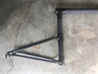
The axle dropouts and smaller tubing on the left are original steel components made by Bob. I cut off the original 1" (25mm) steel tube vertical pivot and replaced it with carbon fiber tubing with 1.625-1.85" diameter (41-47mm). The two black rings are Delrin (acetal plastic) acting as thrust bushings.
IMG_2755.jpg

The trailer body is made of 3 different sizes of carbon fiber tubing. They are sized to fit into each other. The gap size between the tubes is designed to fit either UHMW tape to create a low friction sliding/rotating joint or it can be bonded with epoxy to increase wall thickness as needed, such as where the tube has additional stress from mechanical connections.

View attachment 16

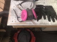
If you're thinking about working with carbon fiber, take Personal Protective Equipment (PPE) seriously. Your body doesn't know what do with this stuff when it's embedded in your skin or your lungs. I always wear gloves and a respirator when cutting or sanding. The holes in the tabletop shown here are connected to a shop vac to create a makeshift downdraft table. I also wear closed shoes, pants, long sleeves and head covering which are only used in the workshop to avoid contaminating my living space with carbon fiber dust and particles.
PPE.jpg

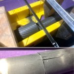
Cutting this stuff is very hard on tools. If you want clean cuts, consider a dedicated hacksaw blade such as this Park Tool Carbon Cutting Saw Blade. Tear-out can happen even with the right blade. The lower photo is a special insert ferrule without the woven fabric outer layer so it's more susceptible to this problem.
cutting CF.jpg

I reinforced the trailer's main horizontal tube with two layers of axially wound carbon fiber braid. One layer probably would have been sufficient but after seeing the importance of torsional stiffness on this kind of trailer geometry I decided to double up. I wound vinyl electrical tape (sticky side out) around the tube to squeeze out excess epoxy and trapped air. It distorted the weave of the fabric a little which is not ideal for optimal strength. Next time, I would probably use vacuum bagging.
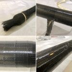
axial wrap.jpg

I added an extra coat of epoxy and wet-sanded. The black color on the sand paper shows that I sanded too far down and abraded away some of the carbon which is a bad idea as it creates weak spots but I figured I've got a little leeway here with my extra layer.
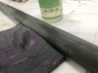
wet sanding.jpg

Where the wheel and suspension attach to the main boom with aluminum brackets, I added an additional layer of fiberglass and used vacuum bagging materials and heat shrink tape to compress the fibers and bleed away the extra epoxy with much better results. The fiberglass layer is necessary to avoid galvanic corrosion of aluminum. Unlike fiberglass, carbon fiber is an electrical conductor and direct contact with aluminum in the presence of water will result in electrochemical corrosion, quickly consuming the aluminum.

View attachment 3

To attach the steel Bob fork to the carbon fiber, I used a carbon fiber wrap joint. I did a dry run with string to visualize the wrapping process, see where the gaps would be and to confirm that the fibers would be oriented correctly relative to the forces on the joint. The white fillet material is epoxy thickened with Cab-o-sil (fumed silica) and microspheres to make a thick paste and to ease sanding. The white tape is vinyl electrical tape perforated with a pin. The last photo is freshly cured epoxy before sanding.
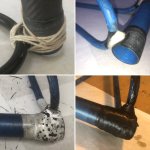
6E37E06A-C88C-4A11-881F-F34FFF5F1689.jpg

Here's the jig I made to wet out the 24k carbon fiber tow with epoxy. This is the "yarn" used to weave carbon fiber cloth.

View attachment 11

Here's a closeup of the tow. There are 24,000 individual fibers in this bundle.
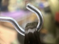
IMG_2656.jpg

My field repair kit includes a small spool of 6k carbon fiber tow and small packets of epoxy for making minor repairs.
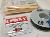
field kit.jpg

Here's the joint after sanding and fairing. It came out much nicer than I expected.
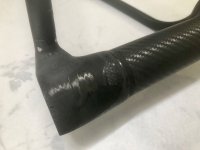
sanded joint.jpg

I cut Delrin rings out of 5/8" (16mm) plate using a heavy duty circle cutter on my drill press then sanded and polished.
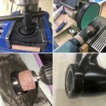
D5C82E65-C95D-48BD-B44C-D8429BCCABD8.jpg

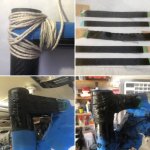
For the 90° joint at the top where two carbon fibers tubes come together, I improvised a jig to hold them in the proper orientation.
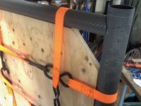
IMG_2711 (1).jpg

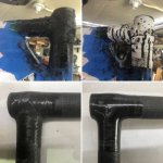
The string wrap showed that the fiber orientation was not matching up well with the forces which will be acting on it so I prepared some strips of unidirectional carbon fiber fabric and used them for the bulk of the reinforcement with CF tow wrapped over the top for good measure.
40EB3E66-21E8-4977-B8A5-D95CAE030938.jpg

I kind of like the look of this joint so I think I might leave it clear with just a UV top coat.
E04664D4-7E90-43C9-86E0-2F1D96193CD0.jpg

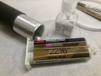
Here's what I'm using to bond carbon fiber to aluminum. This 3M epoxy is crazy expensive compared to most of the other adhesives I use but it's designed to bond well to aluminum and remains flexible down to cryogenic temperatures. The flexibility is critical because aluminum has a high thermal expansion coefficient and carbon fiber has a near zero coefficient (it's actually negative). A bond line controller made of tiny glass beads must be mixed into the epoxy to achieve the optimal gap size between the two surfaces. This gives us concentric alignment between the parts, optimal mechanical bond strength and minimizes galvanic corrosion. Rock West Composites has a good video on this.
IMG_2732.jpg

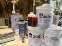
Finally, a few useful additives I keep on hand. These can be mixed into epoxy to change its properties to fit the job at hand: pigment to change color, glass fibers to make stronger filets, cab-o-sil to thicken for fairing, microspheres to reduce weight and ease sanding.
IMG_2727.jpg
 
thundercamel said:
Wow! I applaud your dedication!

Can say that again!
All that stuff you're working with is really, really nasty. I don't even like working with fiberglass.
 
solarEbike said:
The Tilt-o-matic 2.1 trailer body is nearly ready for its first road test.

Tested and approved. The wobbles are gone. I think we have a winner.

[youtube]ZBROu5Ktm2U[/youtube]

The serpentine at 0:40 was me intentionally trying to destabilize the trailer but it was happy to lean with me instead of trying to buck and throw me off.


View attachment 2View attachment 1

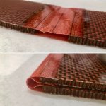
Next up, testing the tilt motor assembly under load for the first time and dialing in this Kevlar living hinge concept so the trailer panels can fold down to airline luggage size.

379894B3-AE8D-464A-B07D-34D399690943.jpg
 
I bought this motor/gearbox combo two years ago and finally got to see it in action today with all the key pieces in place. The overall assembly appears to work as intended. A major milestone for this project. It's a bit loud so maybe turn down your volume?

[youtube]9lghYgTJMbY[/youtube]

The motor is rated as 5.2 rpm no load, 4 rpm under load and it's moving at around 4.5 rpm here. It looks faster than I expected. When making adjustments based on light sensor input, this speed it likely to result in overshoot but the motor controller I'll be using with the Arduino supports PWM motor speed control so I'll be able to adjust the speed as needed. In the video above, I'm controlling it manually using a DPDT switch to move forward, stop and backward by reversing the polarity.

The motor assembly fits inside the carbon fiber boom tube which offers some advantages over the linear actuator I used in my last build — it's lighter, it's protected from dust and water, it's a cleaner looking design and it allows the panel to tilt ±80° which comes in handy early and late in the day. I have not been able to quantify the additional daily Wh from having ±80°tilt range vs. my previous ±40° but I suspect it's not very big. When the sun is close to the horizon, it's passing through much more atmosphere and is much more likely to be shaded by distant objects so those hours contribute relatively little to the total daily solar resource.

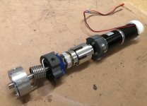
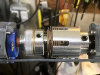
From left to right in the photo below: motor shaft coupler (to main trailer body), torsion spring (to take weight of the solar panel off the motor when fully tilted left/right), 3D printed shaft guide/spring mount/potentiometer mount (gray plastic), potentiometer (blue plastic) to read panel tilt angle, adjustable clutch, 3D printed motor mount (gray plastic), gearbox/motor assembly, 3D printed motor end cap (white plastic).

The clutch protects the gearbox in case of crash or if the solar panel's range of motion is obstructed. It also provides an elegant failover solution in case the Arduino or motor or gearbox fail — the solar panel tilt can be adjusted manually without any tools by simply moving the panel by hand. The friction in the clutch will hold it in place. In the video clip above, you might notice the motor keeps running after it hits the end stop on each side rather than stalling or breaking something. That's thanks to the clutch. Once I add the Arduino, I'll use the position reading from the pot and stop the motor via software before in hits the trailer. I had planned to incorporate limit switches in the design to stop the motor at the ends but finding waterproof options and a good mounting location proved difficult so I'm hoping the clutch will provide adequate protection in case the pot fails or my code results in the panel crashing into the trailer fork.


IMG_1967.jpg


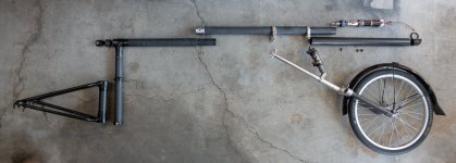
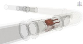
Here's an exploded view showing how all the parts fit together. Every piece is sized to fit inside standard airline luggage. The end caps are 3D printed and use cable glands, o-rings and XT-60 connectors to pass all wiring through the tube while keeping out water. The rear-most carbon fiber tube contains the motor and rotates with the panel.


exploded trailer 1400.jpg


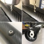
A few shots of the final assembly process. Drilling holes in the completed tubes was nerve-racking but careful planning paid off. I custom designed my own 3D printed sealing washers to match the tube diameter. Last photo shows the motor shaft coupler bonded in place with setscrew for the motor shaft. The large crescent-shaped holes are for wire pass-through. The torsional stress here is not insignificant and I'm relying on the epoxy bond to handle it. Elsewhere, I hedged my bets by also using a mechanical fastener but there wasn't room here for that so I guess I'll find out if my surface prep and bond design were good enough.

FDE6B788-7C36-4659-B522-B39247B9D9F0.jpg

PS: The DNM air shock I'm using here is turning out to be a good fit for this very light weight application. I was concerned that I might not be able to dial in the appropriate preload but it has a separate negative air chamber which provides more flexibility for a design like this.
 
I'm wondering, would it make sense to finish off a drilled carbon fiber hole with a thin coating of epoxy just to seal off that cross sectioned area and tidy up any fraying?
 
wturber said:
I'm wondering, would it make sense to finish off a drilled carbon fiber hole with a thin coating of epoxy just to seal off that cross sectioned area and tidy up any fraying?

That's probably not a bad idea. Some of my holes were backed by an epoxy bonded aluminum insert before drilling and the remaining ones were in the middle of the tube segment where it would be hard to reach to clean up any drips. I backed the holes from the inside before drilling with a scrap piece of Delrin to prevent blow-out and they came out pretty clean so I'm hoping additional epoxy isn't needed. It helps to use a very sharp bit. I have this 115 piece cobalt bit set from Harbor Freight. One of my best purchases from them.

Also, all of my holes are well supported on both sides to spread the point load from the fastener. As long as the fastener doesn't get loose, there shouldn't be any wear and tear at the holes. I use nylon lock nuts or Loctite on all fasteners and check for loose bolts as part of routine maintenance. It's amazing how quickly things can rattle apart on a bike.

IMG_2820.jpg

View attachment 1
 
solarEbike said:
bakaneko said:
... I definitely want to redo it but with satellite grade (35%+) solar panels and at least 150W so I can get an average of 100W.

If you find someone willing to sell you 150W of 35% efficiency PV cells, please let me know.


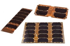
Good news! I found some commercial off-the-shelf pricing for satellite solar cells. 30% efficiency GaAs triple-junction solar cells. Only €500-1000 per watt but I'm sure they would offer a discount for an order of 150W. :D
https://www.cubesatshop.com/product/single-cubesat-solar-panels/


Single-solar-panels.jpg

I'm also salivating over these "low-cost" €2,200 sun angle sensors designed for cubesats. I've been working on improving my photo sensors for determining the optimal tilt angle of the trailer and these have given me some ideas. Fortunately, I don't need dual-axis or <0.5° accuracy or a radiation hardened package. Single-axis and ±5° accuracy is adequate for my solar ebike trailer.

nanoSSOC-A60-min.jpg

On second thought, the rad hardening may come in handy in Australia what with the hole in the ozone layer and all.
 
Wooow !
solarEbike, you're setting a top level of DIY solar bike :shock:
Congrats ! :thumb:

Have you thought about participating to the Sun Trip 2020 during your journey ?
 
solarEbike said:
Good news! I found some commercial off-the-shelf pricing for satellite solar cells. 30% efficiency GaAs triple-junction solar cells. Only €500-1000 per watt but I'm sure they would offer a discount for an order of 150W. :D

I'm thinking that perhaps a small portable nuclear reactor might be more economical.
 
Jil said:
Wooow !
solarEbike, you're setting a top level of DIY solar bike :shock:

Oops. Now I feel bad for not peppering my post with winking emojis. Just to be clear, although I have built a solar panel using satellite cells, I don't consider €500/watt to be remotely reasonable. These cubesat prices are based on very small quantities using top grade cells and include encapsulation. They are intended for use "on orbit".

I have it on good authority that a full set of encapsulated multi-junction PV panels for a solar race car is worth around US$250,000. The satellite cells I used were off-spec rejects of unknown provenance I found on eBay. I spent six months searching, kept getting outbid every time anything popped up until I finally got lucky with a listing titled "200 Solar cells for panel, satellite type, approx 100 W" for which I paid US$244, having been previously outbid at US$600. This was in 2008.

In case you were referring to the non-fictitious parts of my solar bike build, I thank you for your kind words.

Jil said:
Have you thought about participating to the Sun Trip 2020 during your journey ?

I could see that happening in the future. Probably not in 2020. Are you planning to participate?


wturber said:
I'm thinking that perhaps a small portable nuclear reactor might be more economical.

Reading the Wikipedia entry for Radioisotope Thermoelectric Generator: "for situations that need a few hundred watts", "no moving parts" and "Plutonium-238 power density 0.54 W/g." Hmmm... 540 watts per kg sounds pretty good to me. I just need to schedule a visit to a sperm bank first. Also, it might make some of those border crossings a little awkward. "What do you mean I can't take an RTG over the border? Don't you care about the legacy you're leaving for your great grandchildren?"

For what it's worth, I think of solar power as wireless charging from a nuclear reactor which is conveniently located 93,000,000 miles away.
 
solarEbike said:
Good news! I found some commercial off-the-shelf pricing for satellite solar cells. 30% efficiency GaAs triple-junction solar cells. Only €500-1000 per watt but I'm sure they would offer a discount for an order of 150W. :D

The very first e-bike I built, back in the late 1990s, had two arrays of spacecraft type GaAs cells. One on the disc front wheel and one mounted on the frame, they could deliver a combined 100W in full Texas sun. I don't know how much the guy paid for them, but I'm certain beyond any doubt that it was not $50,000 or even remotely close to that. Now I wonder what he was using, and what deal he stuck to get them.

Having worked on that project gave me a warped idea of PV performance for a long time.
 
Chalo said:
The very first e-bike I built, back in the late 1990s, had two arrays of spacecraft type GaAs cells. One on the disc front wheel and one mounted on the frame, they could deliver a combined 100W in full Texas sun. I don't know how much the guy paid for them, but I'm certain beyond any doubt that it was not $50,000 or even remotely close to that. Now I wonder what he was using, and what deal he stuck to get them.

A solar ebike in the 1990s? Impressive. I imagine the guy had to have some aerospace industry contacts to score GaAs cells. Even then, they were not likely flight-grade cells. Back then, commercially available residential PV panels were around $10/watt and around 10% efficiency.

I have an email from Spectrolab from 2007 when I was just getting started. I contacted them hoping that they would find my little project charming and might offer to sell me something from their scrap bin. Instead, they offered me flight-grade 28.3% efficiency cells at $300 each for a 26.6cm^2 cell with a $5000 minimum order. If I'm doing the math right, that works out to $400/watt if you're using the cells at sea level where you're getting 1000 watts/m^2. It's a better deal if you can ride your solar ebike at the top of the atmosphere* where the available solar resource is 1360 watts/m^2. :)

With SunPower selling 24% efficiency bare cells at around $2/watt, it's difficult to make the case for spending the money on satellite grade cells today. Even if you have the budget, you may achieve better results by spending it on weight savings elsewhere, like lightweight lamination and carbon fiber components. Even among solar race car teams with six figure budgets, multi-junction cells are uncommon. Part of that has to do with the race rules being written and re-written to incentivize innovation and engineering excellence over just "biggest budget wins."

* Low earth orbit, not high mountain passes.
 
I took the new trailer out for a road test with the Arduino and light sensors mounted on a breadboard. Aside from some minor teething pains, the system looks like it will work as intended. The handling is so good I can almost forgot that it's back there. With a fully loaded bike the trailer will be even less noticeable.

[youtube]XC8rJD7KI-4[/youtube]

I'll probably need to change out the clutch for a larger one, assuming I can find one which will fit. Even on the highest setting, the current clutch occasionally has trouble overcoming the friction I deliberately designed into the tilt assembly to eliminate backlash and excess play which tends to result it surprisingly loud rattling noises. The motor and gearbox seem to be plenty strong enough to handle the load.

Once I finish dialing in the details, I'll solder the Arduino components together and pot the whole assembly. It will fit inside the trailer main boom tube with sensors mounted on the sides. Most of this video is sped up to 4x normal speed. You really get a sense of how dynamic the optimal tilt angle can be when riding along twisting tree-lined roads late in the day.

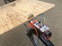
Here's how the breadboard is mounted on the tilting part of the trailer. Since the sensors move with the panel, it is a closed loop system. The sensor values are converted into instructions to move the tilt motor which also moves the sensors. When the values from the two sensors are equal, the motor stops. There's more fine tuning to do on the algorithm: tweaks for low light, variable motor speed, delayed reaction time, etc.

IMG_2837.jpg

I'm finding the frequent tilt adjustments are kind of loud and annoying, particularly when climbing a hill when there's less wind noise to drown out the sound. I might want to have two tracking modes: "responsive" with rapid and frequent adjustments, great for videos and demos and an "economy" mode for real world use which moves the motor slowly to reduce noise and only responds to large changes in light readings with a longer dwell time to minimize adjustments to brief changes in direction.

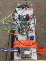
It's a surprisingly simple setup. A couple of $1 photo sensors, a $7.50 motor driver, $12.50 Arduino Metro Mini micro-controller and on optional $17.50 bluetooth BLE module.


IMG_2838 2.jpg


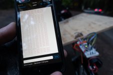
The bluetooth module enables two way communication with my iPhone using a free app from Adafruit. I mostly just use it for debugging. Here, it is displaying the values from the two photo sensors. This can be helpful if the tilt angle looks wrong but it's not clear if the problem is in the hardware or the software.

DSC01243.jpg
 
solarEbike said:
Jil said:
Have you thought about participating to the Sun Trip 2020 during your journey ?
I could see that happening in the future. Probably not in 2020. Are you planning to participate?


Not for the moment, but it's tempting.
 
solarEbike said:
I'll probably need to change out the clutch for a larger one, assuming I can find one which will fit. Even on the highest setting, the current clutch occasionally has trouble overcoming the friction I deliberately designed into the tilt assembly to eliminate backlash and excess play which tends to result it surprisingly loud rattling noises.

So it turns out this was just user error on my part. The two halves of this slip clutch (torque-limiting shaft coupling) come apart and had come loose inside my trailer tube where I couldn't see them. Three of the brass plates were not engaged so the shaft was slipping at a lower torque than intended. It's a good thing, too. The next bigger size clutch would fit inside the tube but wouldn't have room for the wires to pass by it which would really muck up my design intent. Also, the max rated torque of my motor/gearbox is only slightly higher than the current clutch so a bigger clutch would likely stall the motor. Anyway, I think I can make this work.

IMG_2841.jpg


By the way, these motor controllers do not have reverse polarity protection on the Ground/Vin connections. Don’t ask me how I know that. Dramatic recreation here, complete with wishful "putting the smoke back" footage thanks to the magic of movie editing. At last, I've figured out which superpower I want: the ability to put the magic smoke back in.

[youtube]H0PwOVylhwA[/youtube]
 
I’ve been putting in more 10-40 mile rides with the plywood panel on the trailer to try to flush out any failure points and it’s looking solid. Now it's time to finalize the Arduino microcontroller hardware and software.

This is the arrangement of photo sensors I used on the Tilt-o-matic 1.0 trailer. The two sensors embedded in the 1" (25 mm) foam panel represent the end product I was going for: flush with the panel, protected from dust, water and mechanical damage.

I was so sure that arrangement would work that I had only tested the design on a breadboard and went straight to full-on epoxy-and-fiberglass. In practice, it mostly worked. Occasionally, I would get erratic results which didn't give the best tilt angle for the solar panel. I thought maybe the window was too small or maybe light was entering from the sides. Perhaps the sensors need to be more directional? So, I tested the version in the foreground with the black heat-shrink and aluminum angle bracket.

ToM-1.0-photo-sensors.jpg

This was a marginal improvement but I still kept getting situations like this where the panel would get stuck tilted completely the wrong way, facing away from the sun. The reflected light from the ground and the guard rail here was brighter than the light coming in from straight above. Neither sensor is facing directly into the sun. The new trailer's greater tilt range only exaggerated the problem so I could no longer treat it as a low priority.

sensor-fail.jpg

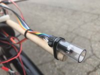
Here's the new design I'm testing now. The sensors will be protected inside a 1/2" (12.7mm) polycarbonate tube bonded to the sides of the panel. This is the test rig with 4 sensors in the tube. The final version will have 2 on the left and 2 on the right.

ToM 2.1 sensor pkg test.jpg

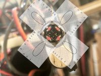
With 4 sensors, we get full coverage from the front and back of the panel. The 2 additional sensors pick up light hitting the back of the panel and trigger the appropriate tilt correction.

4-sensors-coverage.jpg

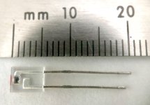
The original sensors were too big to fit in the tube so I found these side-looking phototransistors in a smaller package.

LTR-301.jpg

Eventually, they'll be held in place using a 3D printed mount to help ensure accurate alignment.

Photosensor-mount-Fusion-360.jpg

Here's an example of a situation where the 2 sensor design would have probably failed: a quick u-turn early/late in the day. With 4 sensors, I haven't been able to reproduce the problem so I guess it's working.

[youtube]aMxVxvtYug4[/youtube]

I recently discovered the Arduino IDE's built-in Serial Plotter which is great for visualizing the data coming in from the sensors. Instead of looking at a stream of numbers like this and pretending to be Neo reading the Matrix...

console2.png

...I can watch the 4 sensors in real-time like this. With the Bluetooth Low Energy (BLE) wireless connection to my phone, I can even check this while riding.
4-Photosensor-plotter-animation.gif

There's still more fine-tuning to do on the closed loop. Here it is in auto-tracking mode, showing how it adjusts when pushed out of alignment. There's some overshoot. I should be able to eliminate that by slowing the motor more as the panel gets closer to the stopping point where the sensor values are equal.

Something about this video feels like a low tech version of one of those creepy Boston Dynamics videos where a person shoves a robot and it balances itself to keep from falling over.

[youtube]kafcABrGmHA[/youtube]

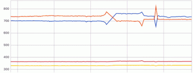
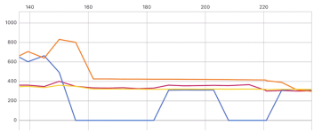
On my first road test, one of the four sensors apparently failed. It's the one with the blue line below. I don't think I exceed any of the specs. It's connected to the 5V pin on the Arduino on one side and to an analog pin on the other, through a 56k resistor to ground. I first noticed it while it was pointed directly at the sun but that may have been a coincidence. It started intermittently reading 0V on the analog input pin and then gave up the ghost entirely shortly afterward. I checked for loose wiring, swapped the analog input pin with one of the other sensors but only got it working again by swapping out the sensor.

Does anyone have any theories about why it may have failed? I'm planning to encapsulate these in a way that would make them very difficult to replace later so I would love to know how I might avoid this in the future.

sensor-fail.png
 
I woke up early this morning to the sound of pouring rain and thought to myself "this is a great opportunity to test the bike in the rain!" Expedition-scale planning has a funny way of redefining what passes for a good idea. At 7 AM, the roads were delightfully empty, the air had a freshly washed scent and, to my disappointment, the rain stopped.

I was descending a steep back road, going into a hairpin turn at exactly 12 mph (19 kph) and congratulating myself on finally getting the hang of taking this very familiar turn using only regen to slow down and not using my brakes at all when my front wheel lost traction and down I went. Completely took me by surprise. Holy. F*cking. Sh*t.
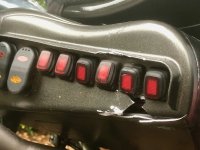
I'm fine. My jacket is a little scuffed. Recumbent bikes tend to result in less extensive injuries thanks to the feet-first position and lower height off the ground. The bike didn't fare so well: bent brake lever, chowdered Rohloff shifter cables, 2 damaged handlebar switches and the wiring pod door completely caved in. The handlebars twisted out of alignment as per their design and were easily re-aligned. The solar roof panel survived unscathed as did the stainless steel mirror (the optics suck compared to glass but they can take a hit like a champ).

Time to order a new print of this door with thicker walls and printed with the recently added 40% glass-filled nylon option.

IMG_2917.jpg

One of the CA remote switches get stuck in the ON position so the CA screen was stuck on "Enter Setup Menu."

IMG_2919.jpg

And I even got it on video!

[youtube]DBZvpafRdNs[/youtube]

I don't need to wait for the NSTB report to know the cause of the crash. It was pilot error. 12 mph is a perfectly safe speed for that turn when the road is dry. Going into it with front wheel regenerative braking on full power? Not so good. My first crash on this bike in a little over 2000 miles (3000 km). Lesson learned, thank you very much.
 
But enough about me. I recently stumbled across an old image on my hard drive and thought I would post some highlights from pioneers in this field.

I first came across this article by David Clay when I was getting started with my solar bike effort in 2007. David built a solar bike in 2000 and rode it from California to Colorado. His trailer weighed 190 lbs (86 kg) without cargo: 32 lbs for 120 watts of solar panels, 60 lbs of lead batteries, 20 lb motor... there are more details in the full article (PDF below). I tried contacting David but the email address listed in the article no longer works. David, if you're out there, drop me a note!

David-Clay-solar-bike-2000.jpg
View attachment David Clay 2001 solar ebike.pdf

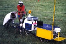
Between 1983 and 1991, Steven Roberts traveled around the U.S. on several versions of this beast. Weighing in at 580 lbs (263 kg), this vehicle had no motor. The 72 watts of solar panels powered his ham radio, satellite communications and assorted other gizmos and doo-dads. It's not a solar ebike but I was compelled to include it here as I feel a kinship with Steven for his lack of impulse control when it came to adding accessories to his bike. Also, that helmet is fierce! More info here.

Steven eventually donated his vehicle to the Computer History Museum in Mountain View, California which, come to think of it, is only a 96 mile (155 km) round trip from where I live. Hmmm...

Steven-Roberts-BEHEMOTH.jpg

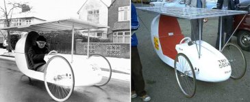
But the grand prize goes to Alan Freeman who built this in 1979. Most internet sources refer to it as a solar "car" but I see a bicycle. I don't care that it had 3 wheels and probably didn't have pedals. Scratch that. I do care about calling something a bicycle if it can't travel any practical distance under human power but come on, riding on wet roads without fenders? Alan was a total badass.

Alan-Freeman-solar-car-1979-1980.jpg

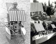
Around 1975 or 1976, Alan built this solar powered boat. I'm pretty sure that's a dual-axis solar tracker. That's right, sun-tracking solar-powered terrestrial vehicles have been around for nearly half a century. Love those vintage solar panels.

Alan-Freeman-solar-boat-1975-or-1976.jpg

This lovingly curated page lists some earlier examples of "solar cars" but until someone unearths photos of Masaharu Fujita's rumored 1977 solar bicycle, I nominate Alan Freeman as the grandfather of solar ebikes.


UPDATE October 9, 2019:
It's come to my attention that I've missed a significant entry in the historical record. In 1984, Ugur Ortabasi designed a four-seat solar powered tandem and his team went on to win the World Championships of Solar Vehicles in 1986. Here's the trailer for a documentary film, currently in post-production.

[youtube]FtCJEEM_tw8[/youtube]
 
Back
Top