Axiom: a 100kW+ motor controller

peters said:
Correct me if I'm wrong, but if the pwm stops in FW mode and the BEMF becomes so high that the phase-to-phase voltage exceeds the battery voltage then the antiparallel diodes start to conduct at the sine wave peaks at an uncontrollable high current. Isn't it true?
If it is so, then the higher voltage IGBT wouldn't extend the safe FW speed range, because the diodes are in forward conduction. The phase-to-phase voltage is limited to Vbat+2*Vdiode by the battery and the diodes, and anything above that would be cut off at high current. In this case the safe FW operation would always be to limit the max possible phase-to-phase BEMF to the battery voltage (considering the failure mode that the pwm stops working).
You are right peters, but thats not the worse case scenario. The fire happens because due to the uncontrolled current you can blow the battery fuse, then it gets open circuited and voltage rises. The fuse is there for a reason, you need to take into account the scenario in which it blows.
In some cases its safer just to open the contactors because the sudden and harsh regen could make the tyres lose traction, thats avoided if you are allowed to open the contactors. I'm not sure that in practice this scenario can make you loose control of your vehicle, but its a sound theory imo.

As Arlin said, what we are going to do for now is to limit the rpm according to the set Vbusmax and the measured flux linkage, those are readily available.
From those parameters you can calculate the rpm that will produce a damaging voltage. In our case it could be set to 600V for example.
 
I understand the fuse, but I find it risky to rely on it to protect the IGBT at the uncontrolled current: maybe the IGBT blows before the fuse. But I don't know IGBT-s, I play only with FETs around 100V, and if I wanted to change to a higher voltage power stage to increase rpm, I would also reconfigure my battery to the matching voltage.
 
peters said:
I understand the fuse, but I find it risky to rely on it to protect the IGBT at the uncontrolled current: maybe the IGBT blows before the fuse. But I don't know IGBT-s, I play only with FETs around 100V, and if I wanted to change to a higher voltage power stage to increase rpm, I would also reconfigure my battery to the matching voltage.

Not sure what you are talking about. But the uncontrolled current in the igbts would be only in the case the back emf was well above the battery voltage and you lost all PWM. In this case we might need to open the circuit between the controller and the battery. We are looking at solutions for this. Many OEMs are running large amounts of Feild weakening it's not a new thing. But the failure mode effect analysis of the topic is complicated. We will for the first while limit rpm to help avoid this as we test the system and come up with solutions.
 
Arlo1 said:
In this case we might need to open the circuit between the controller and the battery.
I mean that opening the circuit with the fuse or the contactors takes some time (tens of ms-s or more), and the semiconductors (antiparallel diode in forward conduction) may fail faster than that. Can't tell for sure, maybe it is not an issue with these giant IGBTs.
 
peters said:
Arlo1 said:
In this case we might need to open the circuit between the controller and the battery.
I mean that opening the circuit with the fuse or the contactors takes some time (tens of ms-s or more), and the semiconductors (antiparallel diode in forward conduction) may fail faster than that. Can't tell for sure, maybe it is not an issue with these giant IGBTs.

I think there is a bit of a delay.
Remember you have internal resistance in the battery and other things that will buy you some time.

This is a good thing to analyze but its really not that big of an issue.
I was spinning the leaf motor like 70% above what the battery voltage would do without FW when it lost sync and it survived!
I am sure if we set realistic settings it will be fine.

Remember we have a lot of protection in our design.
 
peters said:
Arlo1 said:
In this case we might need to open the circuit between the controller and the battery.
I mean that opening the circuit with the fuse or the contactors takes some time (tens of ms-s or more), and the semiconductors (antiparallel diode in forward conduction) may fail faster than that. Can't tell for sure, maybe it is not an issue with these giant IGBTs.

These IGBT modules can withstand 2kW of power dissipation in the body diode for 10ms, but they will blow instantly if you go beyond their max voltage rating.
They are both unwanted scenarios, but if you get to choose... voltage kills faster than current, so if your BEMF is above the powerstage voltage rating... better upgrade the powerstage.
 
So we introduced individual IGBT temperature monitoring. PR here:
https://github.com/vedderb/bldc/pull/92

Hardware was ready but was missing the code to deal with that. The board connects directly to the temp sense connectors, no wiring needed!

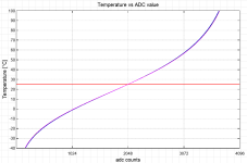
Math is done for the NTC sensors present in FF600R07ME4B11 IGBT modules, it would be cool to make it flexible for different NTC resistances and beta, might do it when me or someone needs that feature.

I'm not showing the math behind this, but it ends in a graph like this:
NTC_plot.png


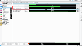
The end result is that you get to see your IGBT temperatures
igbt temps.png


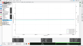
You can limit the current output, in this example at 80°C you will have 100% of the available current output, and will linearly decrease to 0% when it reaches 100°C.
The code will use the hottest IGBT as reference for the temperature derating, not an average or the IGBT in the middle.
temp cutoff.png
If you happen to have a fault during operation, the hottest IGBT temperature gets logged along with other important variables.

This will provide a good feedback in case one of the modules is not properly attached to the heatsink/coldplate. Our DC Link capacitor also comes with integrated temperature sensing, we could do a similar rampdown, or just assert a fault when we provide support for it.
 
shaggythegangsta said:
Hey Marcos, could you please tell us how much time it is going to take to have the support for induction motors? :D
I don't really know, first we need to get Field Wakening and IPM support officially merged before we start the ACIM branch, and we will need to sort out other things as well. ACIM needs some rather complex algorithms to run properly in FOC mode.
You could run an induction motor today driving vesc in openloop mode :)

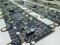
Meanwhile I have fun things to go through:
20190510_164310.jpg

They all programmed ok, so I'll continue working in the MCAD assembly.
 
Thanks Marcos, we will wait for ACIM support, another question: any idea about prices of the control board? (only pcb, fully assembled ecc)
 
shaggythegangsta said:
Thanks Marcos, we will wait for ACIM support, another question: any idea about prices of the control board? (only pcb, fully assembled ecc)
Yes, through the contact form please so we can keep better track. Once you're there you can join the newsletter as well ;)
These beta units are meant for engineers or teams that can give us good feedback.
 
Finally got chance to have a play with my board.....I wont post pictures as it is a bit 'lashed up' at the moment. My main concern is to get the resolver working.

Sadly it seems to be misbehaving :(

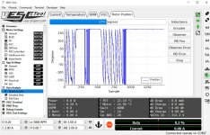
resolversnap.jpg

If the rotor is still it reads around 180 degrees, if I move it I get the trace shown. If I stop it goes back to 180 :(

Any ideas?

Also I took a big deep breath and tried to detect the motor parameters and got the message that inductance was 0 - probably going to need some help!
 
That's great feedback,

2 things could be needing tuning:
1) Sin/cos signal voltage should be within some limits
2) Resolver can be tuned to work at some particular frequency

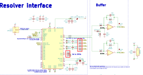
Here is Axiom resolver circuit, pretty much the same as the previous version:
resolver tuning.png

1): According to the datasheet Input signals peak-to-peak voltage should be smaller than 4.0Vpp. Datasheet says typical value is 3.15Vpp (page 3)
So try to measure whats the input peak to peak voltage across C238 (Sin) and C239 (Cos). Ideally with an oscilloscope so you can check you have a sine shape, not clamped or distorted.
If signal is too strong you can increase R156, R166, R167 and R168 values until the signal is within limits.
You can easily locate those componets with the interactive BOM

2): Maybe we can find online if your resolver is intended to work at some particular frequency. I think 10kHz is a popular choice.
Check Table 5. Excitation Frequency Selection on page 11.
That means if you remove R136 and R137 the EXCitation frequency will be set at 10kHz.

If your sin/cos signals are too low I would imagine you need to use a different frequency (2). If they are too high you need to tune the resistor divider (1).
I'll try to find out more info about your resolver.
 
I tried looking for the numbers printed on the resolver with no real joy.

TS2239N484E102
C14742

However, this page shows that I appear to have a resolver with a 4x designation - could this be an issue?

https://www.eminebea.com/en/product/rotary/resolver/resolver/21vrx.shtml
 
x4 means that it provides 4 sine periods per shaft revolution. Its handy if your motor has 4 pole pairs. Imagine for instance that your motor has 14 pole pairs, so 1 mechanical revolution would take 14 electrical revolutions. When a x1 encoder measures 1° at the shaft, it would mean 14 electrical degrees, it gets very hard to reach a good electrical resolution.
Vesc encoder detection will figure out the multiples thing.

From that page its spec'd for 10kHz excitation, so removing those R136 and R137 will set your exc at 10khz. It will be a bit less because the xtal is not exactly 8.192MHZ.
 
bigdaveakers said:
It seems logical that somewhere I need to tell the controller that there are 10 poles and 4 rotors?

Yes, the controller needs to know the offset angle and the ratio of the encoder, its under the encoder tab. This would be the ratio.

If your motor has 10 poles and the resolver is x4 it would create a non-integer ratio, that would be strange.

During encoder detection vesc should figure out both the offset angle and the ratio.
 
marcos said:
bigdaveakers said:
It seems logical that somewhere I need to tell the controller that there are 10 poles and 4 rotors?

Yes, the controller needs to know the offset angle and the ratio of the encoder, its under the encoder tab. This would be the ratio.

If your motor has 10 poles and the resolver is x4 it would create a non-integer ratio, that would be strange.

During encoder detection vesc should figure out both the offset angle and the ratio.

Sorry, I meant that the resolver has 10 poles not the motor.

How do I run encoder detection?
 
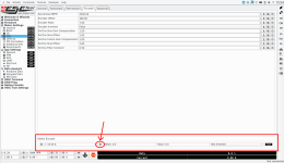
Its here:
encoder detection.png


But first you need to ensure the encoder readings are okay, like you were testing today. The encoder detection will try to make the motor spin, for that you need to setup the current and voltage limits, set the deadtime compensation, etc. It won't work if the angle measured is incorrect.
 
marcos said:
shaggythegangsta said:
Hey Marcos, could you please tell us how much time it is going to take to have the support for induction motors? :D
I don't really know, first we need to get Field Wakening and IPM support officially merged before we start the ACIM branch, and we will need to sort out other things as well. ACIM needs some rather complex algorithms to run properly in FOC mode.
You could run an induction motor today driving vesc in openloop mode :)

Meanwhile I have fun things to go through:
20190510_164310.jpg

They all programmed ok, so I'll continue working in the MCAD assembly.

Boards! I've been looking at the general design and pondering what awesome project I would like to put one of these in and am curious about how the choice of battery/IGBT affects the possible power out. With the reference design at an awesome 100kW, would changing to 600A modules proportionately increase the capability of the reference design (assuming heat is controlled) or are other considerations like switching spikes limiting the power output? Also, would the Axiom DC link capacitor and board clearances safely support an increase in DC link voltage over the reference 400V with 1200V or 1700V IGBTs?
 
SRFirefox said:
Boards! I've been looking at the general design and pondering what awesome project I would like to put one of these in and am curious about how the choice of battery/IGBT affects the possible power out. With the reference design at an awesome 100kW, would changing to 600A modules proportionately increase the capability of the reference design (assuming heat is controlled) or are other considerations like switching spikes limiting the power output? Also, would the Axiom DC link capacitor and board clearances safely support an increase in DC link voltage over the reference 400V with 1200V or 1700V IGBTs?
Ha, I'm glad you ask. We are already using 600Arms (continuous per datasheet) IGBTs, and yet we rate our controller as 300A because thats what serious players in the industry do with a long lasting product.
If we rated our controller in the same way others rate theirs, we would be talking about a 400V * 600A = 240kW controller. And with an easy swap for 1200V IGBTs it would be 480kW! But we are not like them and we rate Axiom in a reasonable, conservative way.
I can assure I'll do peak outputs of 240kW and God knows what will be Arlo1's limit, but that's a different story.

The control board isolation can work well at 800V and you can use the isolated CANbus as an extra isolation barrier. DC link is rated for 600Vdc, you would need a cap rated for higher voltage.
DC link plays a critical role determining switching overshoot that forces you to derate your powerstage. Thats why we carefully made our own dc link.
 
Is there any way of increasing the voltage excitation to the resolver? It seems to be around 2.7V which means the sin and cos inputs are significantly less.
 
bigdaveakers said:
Is there any way of increasing the voltage excitation to the resolver? It seems to be around 2.7V which means the sin and cos inputs are significantly less.

Have you tried different frequencies? Maybe it resonates at a particular frequency making the sin cos signals larger.
The EXC signal is 12V, but you could bypass the 12v regulator and then the EXC is fed directly from the gate driver supply voltage (15V). I'll look up the regulator reference, I dont remember if its U21. (Edit: it is)
Can you check the signals are sine-shaped?
 
marcos said:
bigdaveakers said:
Is there any way of increasing the voltage excitation to the resolver? It seems to be around 2.7V which means the sin and cos inputs are significantly less.

Have you tried different frequencies? Maybe it resonates at a particular frequency making the sin cos signals larger.
The EXC signal is 12V, but you could bypass the 12v regulator and then the EXC is fed directly from the gate driver supply voltage (15V). I'll look up the regulator reference, I dont remember if its U21. (Edit: it is)
Can you check the signals are sine-shaped?

Looks like I need to get myself a scope :)
 
Back
Top