PSWPower Sinewave Controller w/ regen braking

Joined
Feb 1, 2016
Messages
63
I’m familiar with ebike electronics and have been using Regen successfully with the Phaserunner Controller and Direct Drive hub motors.

I’ve been looking for affordable alternatives and found this 250w controller from PSWPower which claims it has Regen. It has a brake input with positive negative and signal. The provided throttle works with the throttle input and spins the motor, but when I connect the throttle to the brake input, it functions, but the signal voltages don’t seem right. The positive reads 4.8v with no throttle connected and 5v between ground and signal. When I connect the throttle, the signal voltage drops to 2.2v and increases to 4.6v when twisting the throttle. This results in the controller not spinning the motor as it sees a high signal.

As per the instructions, I connect the grey wires to enable regen, but nothing happens when twisting the throttle connected to the brake line. The motor can be spun freely by hand.

This is the controller in question:

http://www.pswpower.com/ven.php?cargo.2016-3f-3f7c

I bought three of these and they all behave the same way.

I also tried this controller with a 6.5-inch sensored direct drive scooter motor and it wouldn’t work. So far it works ok with a Xiongda YTW-06, a Bafang G01 (SWXH) and the ‘Edge’ 1500w direct drive motor.

I have some 15A square wave controllers that work with all of the motors mentioned, so it’s a big shame I can’t get it working with the scooter motor. Anyone have an idea of why it might not work with all motors, when a seemingly simpler controller is fine?

I’ve made some videos to show the regen setup not working, also a video showing the noise difference between sinewave vs squarewave controllers on all of these motors. The sinewave is quieter, but is also a bit slower I think.

I’ve noticed that the Sinewave controller has some functions that only work with a display connected, which is strange. For example, there is a -30% speed reduction jumper. With the display disconnected, it defaults to -30% regardless of the white cables being connected or not. I wondered if the regen might be the same, but it doesn’t work regardless of the display being connected or not, or with the grey wires being connected or not.


This is the Regen test

https://youtu.be/QKM5FQowOfU

This is the sinewave vs Squarewave test

https://youtu.be/NEzdY2lrL9s

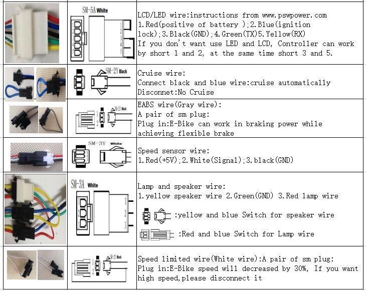
And here are the connections:

474b2f123bae783d685607dfe406018e.jpg


b89c64989a41f294921fc3322d5d3186.jpg


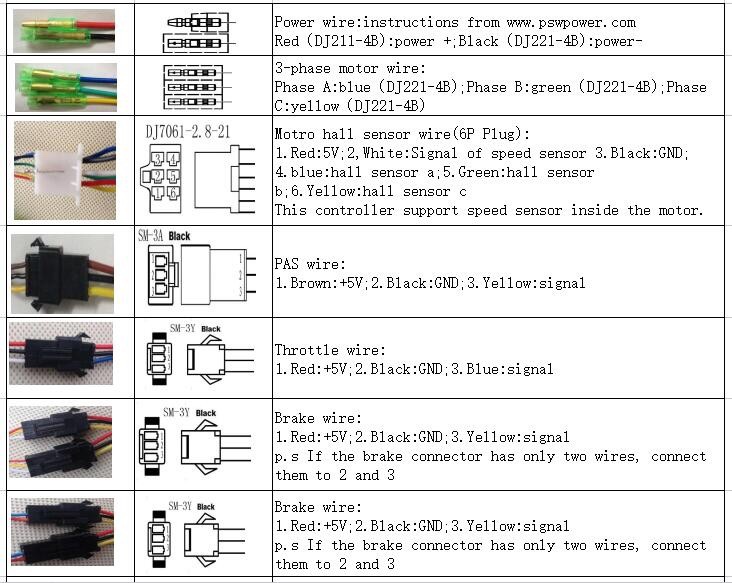
The one thing interesting about this in relation to the regen is that it suggests you can use regular 2-pin brake lever switch’s by shorting the signal to ground. I confirmed this works but only as a motor cutoff. There was no regen braking with either combination of display connected or not, or grey wires shorted or not.

I’m posting this here as the support I’ve been getting from PSWPower is not so good so far. Hope someone may be able to offer some suggestions on what to do!

I think I can return these, but I will be down by two lots of courier and the import duty I paid to get it here.

Thanks in advance Team ES :)


Sent from my iPhone using Tapatalk
 
The regen is not really noticeable unless at speeds in excess of 10mph or so. At least that the case w/26-27" wheels. Brake wires must be shorted to activate.

Also, there's no mention regarding the fact you've enable the regen function in setup? I believe it's off by default.

From the KT3 lcd .pdf manual-

C13 is ABS brakes of the controller and parameters of anti-charge control. The
default value is 0 with the setting range between 0-5, press (UP) button or
(DOWN) button to make selection.
C13 parameter definition table:
C13 Value ABS braking strength Energy recovery efficiency
0 None None
1 Class 1 braking strength Best energy recovery efficiency
2 Class2 braking strength General energy recovery efficiency
3 Class 3 braking strength Weaker energy recovery efficiency
4 Class4 braking strength Poor energy recovery efficiency
5 Class5 braking strength Bad energy recovery efficiency
The recommended value of C13 is 1; other values need to be chosen with caution for
use. (note: reason for caution is high current may cause damage to components not designed to handle it. I use setting #3)
Be sure to note: the higher is the braking intensity level, and the braking strength
will be greater, the greater damage to the motor shaft accordingly.
After finishing the parameter setting of C13, press (SW) button for short to enter
 
The brake input is not variable. It's on or off. The third wire is for systems that use a hall switch sensor in the brake lever. To activate the brakes, the signal wire gets grounded. You can just touch the wires to test. If your brake levers have mechanical switches, the 5v line is not used, just signal and ground.
 
AHicks said:
The regen is not really noticeable unless at speeds in excess of 10mph or so. At least that the case w/26-27" wheels. Brake wires must be shorted to activate.

Is there any indication of it working at lower speeds? With the Phaserunner, you can feel it at least attempting to push back all the way down to a stand-still. I get nothing.

AHicks said:
Also, there's no mention regarding the fact you've enable the regen function in setup? I believe it's off by default.

I've checked with the manufacturer carefully before buying and asked if I needed a display to enable regen - i prefer no display myself - and they said it's not required, so that might be an issue. I was asking specifically if there was any particular display that needed to be used, but only got that previous answer, so I bought a whole kit including the KT LCD1 for the compactness and included USB.

AHicks said:
From the KT3 lcd .pdf manual-

C13 is ABS brakes of the controller and parameters of anti-charge control. The
default value is 0 with the setting range between 0-5, press (UP) button or
(DOWN) button to make selection.

I have a KT3 here i think, so i'll try that and see if it works. Thanks very much for your time to answer :)
 
fechter said:
The brake input is not variable. It's on or off.

Oh really, thanks for confirming. That's annoying as they also confirmed that the braking was proportional on email. :(

fechter said:
The third wire is for systems that use a hall switch sensor in the brake lever.

I'm using a throttle, which has a hall sensor, but the voltage on the signal rests at 2.2v when connected.

So overall, is the braking - even if not proportional - any good for actually stopping, or is it just a little extra boost.
 
AHicks said:
1 Class 1 braking strength Best energy recovery efficiency
2 Class2 braking strength General energy recovery efficiency
3 Class 3 braking strength Weaker energy recovery efficiency
4 Class4 braking strength Poor energy recovery efficiency
5 Class5 braking strength Bad energy recovery efficiency
The recommended value of C13 is 1; other values need to be chosen with caution for
use. (note: reason for caution is high current may cause damage to components not designed to handle it. I use setting #3)
Be sure to note: the higher is the braking intensity level, and the braking strength
will be greater, the greater damage to the motor shaft accordingly.
After finishing the parameter setting of C13, press (SW) button for short to enter

I don't quite get what the different levels mean, as it simply describing efficiency or also strength? Is bad efficiency more strength, but it's using more current from the battery to bring the motor to a stop?

In terms of the caution for the motor shaft, greater damage sounds ominous! I get that regen puts extra forces on the dropouts and the back and forth means you need to really have some decent torque arms in place, but is it something else? I read somewhere that regen controllers were kind of phased out a bit as the current coming back from the motor would damage the controller itself and they were failing more often.
 
With the LCD3 .pdf docs you need to learn to decipher the "chinglish" translation. Not always easy as you can see....

0 is off of course, but then as you go higher 1 > 5, the braking force is increased when the brake switch activates the circuit. It's an on/off thing, but the value is set here.

Keep in mind how the regen works. It's turning the motor into a generator with some fancy electronic switching. On setting # 5, to get the kind of braking force they do get, that "generator" is creating a lot of power (much more than if set to 1 for example), and dumping it into the battery - through the controller. The one conversation I was able to drag a person at KT into regarding this indicated a concern for the controller.

Point being, yes, there's quite a load on the drop outs and torque arms, but there's quite an electrical load that must be dealt with as well.

In addition to the actual braking force applied to the hub, the top line of the LCD3 display has an icon that will display, and the 5 bar battery indicator will scroll (supposedly indicating the battery is being charged). I'm not sure you are going to be able to duplicate the conditions necessary to see that until after you get everything installed and you're rolling down a hill.

Our bikes are used with a very similar controller in a coastal are with a lot of long rolling hills. Set at 3, the regen is often enough to hold the bike at a reasonable speed without using the bikes brakes. The faster you're going, the easier it is to feel what's going on. At speeds under about 15 mph, there's very little braking. At 25mph, it's very noticeable...
 
Thanks AHicks, I’ll give that a shot and report back. [emoji1303]


Sent from my iPhone using Tapatalk
 
davidserin,
I haven't been on here in a while, but will give my 2 cents. Secondly, you're probably more technically inclined than me, but I do have a KT controller with the KT-LCD3, so here goes.

1. As I recall PS Power offers the same products as KT (just rebranded).
2. I'm pretty sure you need the KT-LCD3 (or later/better versions) to enable regen braking on a KT controller. Before I knew what regen was I bought a KT controller (which did not advertise that it had regen). Later, I bought the LCD3 because I wanted/like a display. After plugging in the LCD3 to the KT controller, I was pleasantly surprised to learn that I had regen - not just a shut-off. How can you tell? Because when you brake, the battery symbol flashes as it takes a charge.
3. I think AHicks has misstated. As I recall, for the C13 parameter, 1 is the strongest regen. When I had it set to 1, while going at speed, applying the brake nearly causes the rear wheel to skid (almost feels like it's about to lock-up) (note: I only have ebrake for the rear wheel). So I have C13 set to 3 - this applies a good amount of braking - and still get some juice back put into the battery). Like others, I initially thought the best thing about regen would be the re-charging, but it's actually more valuable in the braking assist. When you're going nearly 30mph, the regen provides a nice confident slow down, with less wear on your brake pads.
 
AHicks said:
With the LCD3 .pdf docs you need to learn to decipher the "chinglish" translation. Not always easy as you can see....

Thanks AHicks, I have it working now. I also tried it again with the display removed and it preserves the settings. Bonus! I'm planning to use this controller on a SWXH with welded clutch. I tried disconnectring the grey wires with the display removed and it did not turn off the regen braking, so i'm not sure what's going on there. I also tried to change the C settings on the KT LCD1 and I can't seem to get to those settings...

I've attempted to write a snappier version of the settings menu here, but the bits in bold still aren't clear to me, if you can shed any light.. it's editable.

https://docs.google.com/document/d/17W8gqhOcRvA8QEUNhc4ZZo36I2AS4kofCOfdoDbfZFg/edit?usp=sharing

AHicks said:
Keep in mind how the regen works. It's turning the motor into a generator with some fancy electronic switching. On setting # 5, to get the kind of braking force they do get, that "generator" is creating a lot of power (much more than if set to 1 for example), and dumping it into the battery - through the controller. The one conversation I was able to drag a person at KT into regarding this indicated a concern for the controller.

Shame you can't see the watts at least, i see the watts display just quickly counts down to zero, but a minus XYZ Watts would be nice! Have you been able to measure the actual current put back at all?

AHicks said:
In addition to the actual braking force applied to the hub, the top line of the LCD3 display has an icon that will display, and the 5 bar battery indicator will scroll (supposedly indicating the battery is being charged). I'm not sure you are going to be able to duplicate the conditions necessary to see that until after you get everything installed and you're rolling down a hill.

This actually works on the test bench if i just pull the throttle and then short the brake sensor. Do you know if there's a way to use either normally closed or normally open switches for the brakes? My son's scooter seems to be the wrong way around for this. Also any clues on how the hall sensor versions are supposed to work? I have some unipolar and bipolar hall sensors here to try. I was hoping for variable regen from the throttle, but i can work with this for the son's scooter :)

Actually, his motor was the only one that didn't work with this controller. I wonder if I can change that with setting P1 or C2 perhaps? It's this little 6.5-inch Direct Drive Motor, which works fine on my generic squarewave controllers (is it Trapeziodal that i mean here?).

https://www.aliexpress.com/item/201...509.html?spm=a2g0s.9042311.0.0.601f4c4doECRYn

Here's the summary i made:"

P1 = magnets x ratio, for speed? =
P2 = how many magnets/revolution for speed sensor = 1-6
P3 = imitation torque mode for the PAS = 1
P4 = Throttle Start without PAS = 1 ???
P5 = Power Monitoring Mode = very confusing!

C1 = PAS = 00 5magnets / 01 8magnets / 02 10magnets / 03 12magnets
C2 = Motor Phase Classification Coding Mode = 1-7
C3 = PAS Default = 1-6
C4 = Startup modes of some sort?
C5 = Current Limiter = 10 is default and max, 0.5A reduced each step down
C6 = Backlight Brightness = 1-5
C7 = Cruise On = 1
C8 = Motor Temp On = 1
C9 = Startup Password On = 1 (then set 3-digit code)
C10 - Factory Reset
C11 = Attribute Selection Mode = ????
C12 = Low Voltage Cut-off = ???
C13 = Regen Brakes = 0-5
C14 = ???

AHicks said:
Our bikes are used with a very similar controller in a coastal are with a lot of long rolling hills. Set at 3, the regen is often enough to hold the bike at a reasonable speed without using the bikes brakes. The faster you're going, the easier it is to feel what's going on. At speeds under about 15 mph, there's very little braking. At 25mph, it's very noticeable...

Good to know, thanks.

I have some questions leftover after all of this that i'll try to answer myself, but on the offchance, if anyone knows!.. :)

1 - Can the controllers use the speed sensor wire for motor temperature readings? How else would one take advantage of this feature?

2 - will it work with my small motor 6.5-inch Direct Drive Motor and how. I get slow forward movement, but it eventually cuts out. I've tried every combination using Lyen's little chart.

3 - I've run some of these controller on 52v and they are usually fine, but I'm wondering if Regen will still work since it relates to the battery voltage. I guess this also questions if there is a high voltage cuttoff for this as I'd like to hope it does to avoid damage, right? I presume these controllers auto-sense the battery voltage, but maybe a small step to 52v might confuse it..

4 - i'd like to know the current rating for the light output, but not sure where to find that.

5 - are there any better resources for this controller anywhere?
 
rote said:
davidserin,
I haven't been on here in a while, but will give my 2 cents. Secondly, you're probably more technically inclined than me, but I do have a KT controller with the KT-LCD3, so here goes.

1. As I recall PS Power offers the same products as KT (just rebranded).

Thanks for chipping in, really useful to hear your usecase. I'll see what's on the KT website in terms of resources.

I really like the idea of saving on brakes. For my Son's scooter, this can be activated on the rear electric motor when he uses the front brake, which is currently the only one on there! I'm not expecting much more than 5-10% energy back, but i'll take whatever i can get!

I've used a few more pro controllers and was looking for something i could put on the family bikes and I'm pretty pleased with it now. Using the phaserunner, it's possible to use the deadband of the brake levers to set a variable regen zone before the actually pads hit the rotors. I just use the physical brakes if in want to lock the wheel up. :D

But this is a really good alternative for a tenth of the price. Shame about the inability to do it proportionately.
 
fechter said:
The third wire is for systems that use a hall switch sensor in the brake lever. To activate the brakes, the signal wire gets grounded. You can just touch the wires to test. If your brake levers have mechanical switches, the 5v line is not used, just signal and ground.

Is this for those hydraulic brake sensors that can be stickered on? Might be nice to know how i could make this myself as i have a selection of hall sensors and magnets. Does anyone know the voltage range, would it be low below 1v and high anything above?
 
In case you didn't know about it, for KT controllers and LCD3 displays, Casainho/stancecoke/etc have written open-source firmware to replace the original, that gives you control over everything in it.

I have never used it (don't have these controllers) so don't know any details, but you can search their posts for the threads about it. It's a lot of reading, I suspect, but worth if it it improves the system for you. :)
 
amberwolf said:
In case you didn't know about it, for KT controllers and LCD3 displays, Casainho/stancecoke/etc have written open-source firmware to replace the original, that gives you control over everything in it.

I have never used it (don't have these controllers) so don't know any details, but you can search their posts for the threads about it. It's a lot of reading, I suspect, but worth if it it improves the system for you. :)

I spotted that and wondered if it applies to my controller, sounds like it thanks, i'll read into that and give it a go :bigthumb:
 
This explains a lot about what is possible with the KT controller:

https://opensourceebikefirmware.bitbucket.io/windows_instructions/index4.html

There'sa connection on the circuit board to make the regen linear, so i'm going to try and wire that up. Incidentally, this is also the connection for temperature sensor if chosen...

Regen --> linear: linear regen via an analog voltage on pad X4, you can use an additional thumb throttle for example

Temperature cal a: Factor a in the calibration function temperature in °C = a * ADC value + b. For temperature calculation from external sensor connected to pad X4 and GND. Temperature is shown in the LCD3 but not processed to reduce power if temperature is getting to high actually.

I wonder if i could use both!
you can't
 
I doubt it--generally an input can only be used for one thing or another, without external multiplexing hardware and appropriate software changes.
 
rote said:
davidserin,

3. I think AHicks has misstated. As I recall, for the C13 parameter, 1 is the strongest regen. When I had it set to 1, while going at speed, applying the brake nearly causes the rear wheel to skid (almost feels like it's about to lock-up) (note: I only have ebrake for the rear wheel). So I have C13 set to 3 - this applies a good amount of braking - and still get some juice back put into the battery). Like others, I initially thought the best thing about regen would be the re-charging, but it's actually more valuable in the braking assist. When you're going nearly 30mph, the regen provides a nice confident slow down, with less wear on your brake pads.

From the LCD3 manual I quoted above-
"Be sure to note: the higher is the braking intensity level (I'm assuming "intensity level" = the values 1-5), and the braking strength
will be greater, the greater damage to the motor shaft accordingly."

I'm interpreting that to mean the higher the value, the greater the braking power, as well as the greater the potential for damage to the motor shaft/drop outs. My thoughts anyway, FWIW.
 
QUICK UPDATE

Slow Start

This KT controller ramps up to full torque quite slowly. Is there any way to decrease the ramp up time?

Regen:

I've managed to get the Regenerative braking working using the KT LCD3 display and changing the setting C13 to 1. It's not possible to access these settings using the LCD1 that i purchased with the kit. The regen braking works when the screen is disconnected. I noticed that the regen makes a vibration, even though the acceleration is completely smooth and silent. I have the intensity set to 5, which gives the strongest braking force. The vibration is quite off-putting. Has anyone else noticed the vibration? I stil get it even when reducing the braking amount, albeit less and less.

6.5-inch scooter motor:

I managed to get this motor working with the controller by changing setting C2 for motor phase classification. It was smooth from 2-4, and vibrating on 0,1 and 5. So i chose 3.
 
Back
Top