Blown new MOSFET controller!

Vikingimike01

100 mW
Joined
Mar 31, 2019
Messages
48
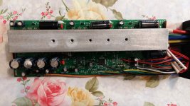
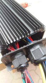
Hey! I installed my first 5000W ebike kit, it's a 72v 120A mosfet controller.

I wired everything correctly, and only plugged in:

1 of the 2 brakes
Display
Throttle
Wheel 3 different wires with the colours
hall sensor

Nothing else. And, i wired 2 72v battery packs into parallel. Was careful with the colors/polarities.
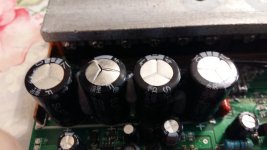
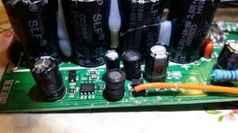
First time I plugged it in, i heard a small spark at the battery connection where i plugged it, i got scared, removed it quickly. Remembered it's normal, tried to plug it in the second time, when it had the same pop there, some sparks, but then like 1 second later I heard a pop from the MOSFET controller, and a deep sounding one.
Nothing works. The wire did not heat up on the battery either.

What can I do?
 
It was not parallel! I ran ~160v trough it!

What do I do to fix the controller? I can't remove it from the casing, no matter how hard I pull. I watched a YT video.

Is there like any overvolt protection in it? It's a RisunMotor controller.
 
Try posting a picture of it. On many styles, you need to remove all the screws along the side for the heat spreader before the board can slide out. Putting 160v to it is likely to have blown more than just the MOSFETs. It may not be worth repairing, but you have little risk in taking it apart to take a look since it's blown anyway.
 
Vikingimike01 said:
It was not parallel! I ran ~160v trough it!

What do I do to fix the controller? I can't remove it from the casing, no matter how hard I pull. I watched a YT video.

Is there like any overvolt protection in it? It's a RisunMotor controller.

In a moment of mental dullness, I once plugged my 12vdc to 120vac inverter into a 36vdc power supply (battery). Poof!! Instant magic smoke. It killed a capacitor which was easy to identify and also easy to replace. Hopefully your situation is similar and will be as easy to fix.
 
I took all the screws out, and tried to pull by the wires with no luck. Not comming out! It has a nice smell inside and lots of white fluffy cotton like material.
 
Vikingimike01 said:
I took all the screws out, and tried to pull by the wires with no luck. Not comming out! It has a nice smell inside and lots of white fluffy cotton like material.

I wouldn't pull on the wires. Like fechter said, post some pics and we may be able to give you hints on how to get into it. In the meantime, check the entire case carefully for any screws you may have missed. It is possible that some screws are hidden by stickers or other glued on elements (like rubber feet?). Also, the board might be glued in place with some blobs of silicon cement.
 
I attached the picture. Other side same thing. Removed. Can't get it out. Nothing looks fried from the back.
 

Attachments

  • ass.jpg
    ass.jpg
    139.9 KB · Views: 1,795
Could there be a high voltage safety fuse by any chance? It's a RisunMotor MOSFET 120a 72v controller.
 
Posting just a single picture with such a limited view is a poor way to help others help you out. All I can offer is to look at those black nuts that the wires pass through to see if they can be loosened enough to let you slide that one cover further down the wire bundles to get a better look inside.

Bottom line is that if someone got the board in there, there must be a way to get it out. More/better pics might help someone here help you out.

There might be a fuse, but I doubt it would make a loud pop sound.
 
Vikingimike01 said:
I attached the picture. Other side same thing. Removed. Can't get it out. Nothing looks fried from the back.

A picture from the other side would be helpful, because on that side, you should have the whole cover off. I also agree, loosening those wire nuts to slide the cover further to get a better look would help. in the end, you could cut off the connectors and slide the cover all the way off.

Is it something like this one, but silver? Looks like no exposed screws, from the crappy pictures, so is the body all one piece? (is the bottom fixed to the body):

https://www.alibaba.com/product-detail/Professional-36V-48V-60V-72V-5000W_60772549133.html?spm=a2700.galleryofferlist.normalList.2.53b54ad1VxVI5U
 
There will be screws holding the heatsink bar the FETs are mounted to, to the case itself. Those must be removed to take the controller apart. They could be along any side, or top or bottom.


That said, the fluffy stuff is what's left of the insides of the main power capacitors, and any others along the main power bus. Those are easy to replace.

But the MOSFETs are also on that bus, and are probably blown, even if they don't look like it, so they'll likely ahve to be replaced.

THen there is the LVPS (low voltage power supply) that converts the battery voltage on hte main power bus to the 5v and 12v/etc that powers things like throttles, MCU, hall sensors, etc. If you have a "keyswitch / ignition / doorlock" wire, and that was NOT connected to battery voltage at the time of the overvotlage, then the LVPS and parts downstream are likely all intact. Otherwise...if the LVPS blew, it *could* have passed high votlage downstream and damaged other things. Not that likely but possible.

I doubt there's a fuse. Never seen one in an "ebike" controller yet. They expect the user to have an external one...but a fuse wouldn't have stopped the damage even if ti was there.
 
E-HP said:
Vikingimike01 said:
I attached the picture. Other side same thing. Removed. Can't get it out. Nothing looks fried from the back.

A picture from the other side would be helpful, because on that side, you should have the whole cover off. I also agree, loosening those wire nuts to slide the cover further to get a better look would help. in the end, you could cut off the connectors and slide the cover all the way off.

Is it something like this one, but silver? Looks like no exposed screws, from the crappy pictures, so is the body all one piece? (is the bottom fixed to the body):

https://www.alibaba.com/product-detail/Professional-36V-48V-60V-72V-5000W_60772549133.html?spm=a2700.galleryofferlist.normalList.2.53b54ad1VxVI5U


It's the same one I think, yes. That one.
 
amberwolf said:
There will be screws holding the heatsink bar the FETs are mounted to, to the case itself. Those must be removed to take the controller apart. They could be along any side, or top or bottom.


That said, the fluffy stuff is what's left of the insides of the main power capacitors, and any others along the main power bus. Those are easy to replace.

But the MOSFETs are also on that bus, and are probably blown, even if they don't look like it, so they'll likely ahve to be replaced.

THen there is the LVPS (low voltage power supply) that converts the battery voltage on hte main power bus to the 5v and 12v/etc that powers things like throttles, MCU, hall sensors, etc. If you have a "keyswitch / ignition / doorlock" wire, and that was NOT connected to battery voltage at the time of the overvotlage, then the LVPS and parts downstream are likely all intact. Otherwise...if the LVPS blew, it *could* have passed high votlage downstream and damaged other things. Not that likely but possible.

I doubt there's a fuse. Never seen one in an "ebike" controller yet. They expect the user to have an external one...but a fuse wouldn't have stopped the damage even if ti was there.

Yes, there were like 6-8 screws at the top. No screws anywhere else. I'll try posting pictures more.

I can't remove the front plate, only slightly, I removed the black plastic nuts from the wires, and they are hot glued as well..


I'm going to have to wait for the seller's answer, if he can't do anything, I may need to use a metal cutter to cut the case open. It won't get out. I tried pulling, pushing from the other side.. nothing. From the back side, there are several 100v big capacitors, they look fine.
 
"6-8" seems odd. I'd usually expect a definite single number....

Anyway, if those screws were all in a row, about an inch apart, in the space between fins on the case, then those are probably the FET bar screws.

IF the controller still doesnt' slide out with both endcaps removed, and those screws, then the heatsink bar is probably just stuck to the case by dried out thermal paste.

But it is possible that they actually glued the edges of the board to the case inside, which will make it much harder to get out.

If you have to cut the case open, you have to use something to catch all the metal bits, because any that get on teh electronics may end up under things and shorting stuff out where you can't see it till it's too late.

If there are stickers anywhere on the case, they are probably covering the screws for the FETs. There are always fasteners to secure whatever heat transfer bar they are attached to on the board inside, to the outside case.

They may not be obvious, but they are there. ;)

I have seen one generic cased controller that has a removable lid, and then the FET bar screws are accessible from inside. The case on yours, from the one pic you have so far, does not appear to be designed this way, but we can't see hardly any of the casing.

You'll just need to post more pics of all the angles and sides and ends and top and bottom and whatever can be seen of the inside.
 
I'll post more pics. The screws were in a row about an inch apart. It may be hot glued or just glued cause under the heat sink screws there was like a weird glue kinda material that was still on the screw treads. Like hot glue...
 
if it was a white creamy paste (or flaky if dried out) tahts probably just thermal paste. if it was blue or red it's probably loctite.
 
Hello! Update.

I got the board out. Took 3 pics of the things I found damaged. Theres a pic wich shows the whole board too.

There is white soot on the board, very minimal, wich is probably leaked electrolite from the capacitor. Look at the top left corner.
 

Attachments

  • 1.jpg
    1.jpg
    76.8 KB · Views: 1,675
  • 2.jpg
    2.jpg
    126.4 KB · Views: 1,675
  • 3.jpg
    3.jpg
    126.2 KB · Views: 1,675
Definitely blew a cap.
I would suggest removing any damaged looking caps then check for FET shorts. Checking for shorts can be done with an ohmmeter by measuring each phase wire against each main power wire (6 combinations). Measure both directions by swapping the probes. A good measurement will look like a diode. If the resistance is near zero in both directions, that's a shorted FET.

If none of the FETs are shorted, there's a chance it might work if the bad caps get replaced. The other weak link is the voltage regulator. This can be tested without the caps installed. Apply power and see if you get 5v on the throttle or hall sensor wires.
 
No idea how to do that.. I may go to an electricity store and let them handle it, if they can. The seller is helping me as well, but I need to wait 1 day for each response.
 
A little late in this thread to be asking, but do you have:
Basic soldering skills?
A volt/ohm meter?

If the answer to either of those questions is No, then just get a new controller, and set this one aside until both answers are Yes, then try repairing it.

Not sure what the rate is to have electronics repaired in your area, but I’m guessing I could buy a few controllers for what they’d charge here.


Sent from my iPhone using Tapatalk
 
I have an old volt meter that has like a thing that can measure AC DC volt up to 500v, and battery. No soldering skill, but can weld. No ohm meter.

This is a 5000W controller so doubt it.
 
If you want to do e-bikes you will need a decent DMM. $20 range should be fine. And RC watt meter is also a good idea.

Learning to solder is easy. I have been using a Velleman VTSS5U for years. You will need something approaching 100w if you want to pull the fets. You should also get several different tips with varying widths to them. You will also need a solder-sucker to cleanly remove the solder. Usually under $10 for a decent one.


To change that capacitor, you need to cut the glue away from it. A paint stripping gun or other heat to loosen the glue and a hobby knife (exacto) or other kind to slide down the edge of the can. You might even be able to heat the tip of hobby knife on it's own and slip it down the side of the can. Heating the knife tip will take multiple attempts because the knife will cool quickly. Once the glue is loose, flit the circuit board upside down and heat the solder until it is fluid and use the solder-sucker. Once the solder is removed, replace the blown cap with a new cap and test your system to see if it is working. With luck, it is working you do not have to replace the fets.

Good Luck.

:D :bolt:
 
Replacing FETs on a controller is probably not a good beginner project. But you should certainly get a good digital voltmeter and learn how to use it. They are quite inexpensive these days.

Let's hope the seller comes through with a warranty replacement.
 
I hope so.

I have an old 100W solder thing. I'll try to replace it if the seller can't/wont. Probably will, theres a 1 year warranty.
 
Back
Top