Cheap FOCer (VESC 4.12 based design)

Thanks! Honestly this project file in Altium is sort of crappy and is a patchwork job due to a lot of constraints I had to deal with while designing in Altium. I may attempt to convert it to a KiCAD project file using the Altium2kicad plugin. Altium, and it's particular flavor I have from my company, has been like trying to operate a space shuttle just to go to the grocery store. While I'm more familiar with it than before, I've discovered that KiCAD simply offers more freedom and is widely available.

That being said, I can still make an attempt to clean up the Altium design files and upload to the repository. No promises on it's quality though.
 
if you want, i can do the Altium clean-up for you :)

i work with Altium dayly.

what version of Altium did you do the design in? i have 13.1,14,17,18 installed LOL
 
@nieles I may take you up in that offer if I don't do any good on my own. I appreciate it!


The beta testers and I are starting to receive the beta controllers in the mail. I’ll be testing one of mine in the lab next week to see if there are any improvements over the proto-FOCer. I’ll be posting results here just as I’ve done in the past.
 
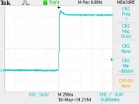
TEK0000.JPG
Switch Node @Vsupply = 54V

Ok so I fired up the beta version in the lab. @54V there was only a spike of 55.6V at no-load. This is much better than the prototype and is most likely due to the improved layout.

The owner of the dyno I was using before is currently using it for his own tests. I won’t be able to use it for a while. However, I’m sure this version performs better under load as well when it comes to voltage spikes.
 
Hey, I've been following the thread for a while waiting for some files to be posted and here they are! Great work so far, it's looking like a super cool alternative to the usual cheap Chinese controllers.
I'm ready to order a PCB and parts and build one for myself to test. Are the files on Github good enough for that, or are there some fixes that haven't made it in etc. Is there something else I should be aware of (other than it's a beta stuff might break) ?
 
shaman said:
TEK0000.JPG
Switch Node @Vsupply = 54V

Ok so I fired up the beta version in the lab. @54V there was only a spike of 55.6V at no-load. This is much better than the prototype and is most likely due to the improved layout.

The owner of the dyno I was using before is currently using it for his own tests. I won’t be able to use it for a while. However, I’m sure this version performs better under load as well when it comes to voltage spikes.

That looks pretty clean! Awesome work!!
 
neo2121 said:
Are the files on Github good enough for that, or are there some fixes that haven't made it in etc. Is there something else I should be aware of (other than it's a beta stuff might break) ?

The only thing wrong I've found so far is the lack of 5V connected to pin 2 of the SERVO header. You can see the pinout on the GitHub. However, serious testing has yet to begin. The beta team is still installing these controllers and prepping their rigs. I'll be updating the GitHub page with the errors I find. I'll update the Gerbers after I feel that we have completed adequate testing. So far, I've had a tester successful in running an electric mountain board with dual controllers albeit with some acceleration and duty cycle issues. I suspect these are software issues and not hardware.

nieles said:
That looks pretty clean! Awesome work!!

Thanks!
 
After reading this thread, I thought some of you may be interested in these MOSFET choices.
V A Rds(mΩ) GS (V) QG(nC) RθJA (C/W) Rise Fall Notes:
CSD19506KCS 80 273 2.2 20 120 62 11 10 better than 3077 in every category
CSD19536KCS 100 259 2.5 20 153 62 8 5 TI recommends this one for 48v

I am an EE and have worked in power electronics. Good luck with all your efforts.
 
$3.3 * 6 = $20
$1.19 * 6 = $7.2

They could be better, but there is only so much upgrading that can be done before it becomes Not-So-Cheap-Focer. Is there an assesment at how much more efficiency we'd get from those $13?


1. Have you considered going for 12 mosfets from the start? 10+ and we get the first volume discount, thus paying less in total for better effect in the end.

2. I see those 0.1" headers and I am not impressed. How are we supposed to make reliable wire-to-board connections with those? Right now I am looking for solutions for my projects, and it seems like investing in a crimp tool and some connector system would be the best way forward. But I only have a slight idea which connector system I'd want (JST XH, for compatibility sake with balance wires).

3. $5 microcontroller.... can this seriously not run on a $2 one?
 
specing said:
1. Have you considered going for 12 mosfets from the start? 10+ and we get the first volume discount, thus paying less in total for better effect in the end.

I'm doing a 12 FET version for my newer controller design. Have you found where 12 FETs are cheaper than the 6 FETs even with the 10unit pricing?

specing said:
I see those 0.1" headers and I am not impressed. How are we supposed to make reliable wire-to-board connections with those?

You don't have to use the standard pin headers. You can use whatever connector you want with 0.1" pitch. You also can just solder wire directly in the connector thru-holes for a reliable connection. Yes I have considered other connectors but for my newer controller design.

specing said:
3. $5 microcontroller.... can this seriously not run on a $2 one?

You are seriously welcome to redesign this for a $2 controller. I certainly don't have the time. Note that the firmware/software created by Benjamin Vedder is only for the particular microcontroller used in this controller. I'm not sure that a $2 microntroller will have the power and peripherals to match the capabilities of any VESC based design.
 
shaman said:
I'm doing a 12 FET version for my newer controller design. Have you found where 12 FETs are cheaper than the 6 FETs even with the 10unit pricing?
No, I have not been looking for them, yet.

shaman said:
You don't have to use the standard pin headers. You can use whatever connector you want with 0.1" pitch. You also can just solder wire directly in the connector thru-holes for a reliable connection. Yes I have considered other connectors but for my newer controller design.

Which ones? From what I see on your github photos, you are using Mini-PV (aka Dupont) for this project. There is an article here by a person discussing some connector systems and crimping tools: http://tech.mattmillman.com/info/crimpconnectors
It seems that Mini-PV can be effectively crimped with a combination of Engineer PA-09 ($40) for wire and YTH 202B ($9) for insulation.

On the same website it is also discussed why we should never solder to connectors not designed for soldering, and I suppose the same applies for soldering directly into 0.1" through-holes.

shaman said:
You are seriously welcome to redesign this for a $2 controller. I certainly don't have the time. Note that the firmware/software created by Benjamin Vedder is only for the particular microcontroller used in this controller. I'm not sure that a $2 microntroller will have the power and peripherals to match the capabilities of any VESC based design.

Understandable, I was just wondering if anyone had a look at it. I have not yet dug into the required functionality, but I know that even $1.5 stm32 are absolutely packed with features.
 
specing said:
shaman said:
You don't have to use the standard pin headers. You can use whatever connector you want with 0.1" pitch. You also can just solder wire directly in the connector thru-holes for a reliable connection. Yes I have considered other connectors but for my newer controller design.

Which ones? From what I see on your github photos, you are using Mini-PV (aka Dupont) for this project. There is an article here by a person discussing some connector systems and crimping tools: http://tech.mattmillman.com/info/crimpconnectors
It seems that Mini-PV can be effectively crimped with a combination of Engineer PA-09 ($40) for wire and YTH 202B ($9) for insulation.

On the same website it is also discussed why we should never solder to connectors not designed for soldering, and I suppose the same applies for soldering directly into 0.1" through-holes.

i think you are mixing up two different things here.
it is definitely not recommended to solder to a crimp terminal. (as they are designed for cimping)
soldering something to a pad on a pcb is no problem. for the pcb it wont matter if yo solder a pin header in the holes or just a wire.
 
specing said:
Which ones? From what I see on your github photos, you are using Mini-PV (aka Dupont) for this project.

There are other 0.1" (2.54mm) pitch connectors out there. Here's some below for example. Use whatever you want
https://www.aliexpress.com/item/32952337808.html?spm=2114.search0604.3.9.13005d26p2Trhv&ws_ab_test=searchweb0_0%2Csearchweb201602_6_10065_10130_10068_10890_10547_319_10546_317_10548_10545_10696_453_10084_454_10083_10618_10307_537_536_10059_10884_10887_321_322_10103%2Csearchweb201603_52%2CppcSwitch_0&algo_expid=daf90aa5-fb43-460d-93c8-338d9365f37b-1&algo_pvid=daf90aa5-fb43-460d-93c8-338d9365f37b

nieles said:
soldering something to a pad on a pcb is no problem.

Yes this is what I mean. Soldering the wires directly to the PCB.
 
nieles said:
i think you are mixing up two different things here.
..
soldering something to a pad on a pcb is no problem. for the pcb it wont matter if yo solder a pin header in the holes or just a wire.

It wont matter for the PCB, but the problem will be inside the wire, as the solder will creep up under the insulation and create a mechanically weak point. See article. The classic pcb is only 1.6mm thick, it is not enough to mechanically secure the wire against this.
 
Hi Shaman,

How are things progressing ? I've been checking out out VESC code, and even though the software offers a wide range of possibilities, it's definitely not ebike optimized. Implementing PAS, torque Sensors, E Brakes, progressive Regen and most importantly a display always requires some fiddling not everyone is able to do. So I wonder what's the compatibility level of your FOCer and the open source firmware project. They have done some work on Lishui controllers too, which use the same chip than your device, IIRC. What do you think ?
 
qwerkus said:
How are things progressing ?

Very well actually. One of the beta testers has done several test runs while gathering great data. So far the Cheap FOCer is performing as well as any other VESC 4.12 based design. It does run much cooler than other VESC controllers even with minimal heatsinking. I'm sure that's due to using TO-220 FETs rather than DPAKs.

qwerkus said:
even though the software offers a wide range of possibilities, it's definitely not ebike optimized.

True. The firmware/software was born from the e-skate world. It's been a while since I've looked at the open source firmware project. I'll have to see if there's any compatibility. If not, modifications to the VESC firmware is still very possible for someone fluent in C programming. Features that cater to ebikers can be added. I simply don't have the time right now for both hardware and firmware development or else I would seek to add the features you have mentioned.
 
shaman said:
I simply don't have the time right now for both hardware and firmware development or else I would seek to add the features you have mentioned.

That's what I thought. software is super time consuming. but it seems the team behind the open source firmware is also interested in your FOCer, so maybe they'll help. As soon as you give the green light,I'm going to get a sample (maybe even a batch like you did,but in europe) and check out the extend of necessary coding to do. I need a new 1000W 54V controller anyway. If your FOCer can handle it, I'm on!
 
qwerkus said:
I need a new 1000W 54V controller anyway.

I'm glad that team is interested! However, you and that team may want to wait for my newer controllers. The new ones are estimated to handle up to 84V and use the better VESC 6 platform. 54V doesn't leave much margin for the Cheap FOCer.
 
shaman said:
qwerkus said:
I need a new 1000W 54V controller anyway.

I'm glad that team is interested! However, you and that team may want to wait for my newer controllers. The new ones are estimated to handle up to 84V and use the better VESC 6 platform. 54V doesn't leave much margin for the Cheap FOCer.

Ok,good to know. I'll get a cheap KT than in the meantime, and hack the OS firmware on that platform. Count me in though for the beta of the serious FOCer.
 
https://forum.esk8.news/t/cheap-focer-vesc-compatible-4-12-redesign/1510/86

A member of the esk8 forums put together 2 Cheap FOCers. There were some lessons learned when it comes to soldering the DRV. It is critical that the DRV ground pad is properly soldered. You can scroll through the linked thread if you want the details. After the DRV was soldered properly, the Cheap FOCers were functional.

I'm still adjusting the design in very minor ways based on feedback. The v1.0 release with only have minor changes. One of the more significant changes is the addition of a through hole pad directly underneath the DRV so that the ground pad can be easily soldered with a regular solder iron. See image below.

 
shaman said:
https://forum.esk8.news/t/cheap-focer-vesc-compatible-4-12-redesign/1510/86

This thread is awesome. Love how the skate guys are crafty! I'm really looking forward to build a "serious focer", once you give us the green light. I'd work on implementing libraries for the standart ebike displays and maybe see if stancecoke's beta open source firmware for lishui would work. Much simpler than adapting vesc to ebike code.
 
qwerkus said:
shaman said:
https://forum.esk8.news/t/cheap-focer-vesc-compatible-4-12-redesign/1510/86

This thread is awesome. Love how the skate guys are crafty! I'm really looking forward to build a "serious focer", once you give us the green light. I'd work on implementing libraries for the standart ebike displays and maybe see if stancecoke's beta open source firmware for lishui would work. Much simpler than adapting vesc to ebike code.

Yeah adding firmware features is in my creative backlog with ebike display support being one of those features. My embedded kung fu is not strong anymore and it will take time for me to develop it. It shouldn't be too hard as long as the displays use some kind of standard protocol (like UART). Until then, you'll have to link a phone or something via bluetooth with a VESC app for a display on your rig.
 
Hi, I'm gonna take a stab at this design for a project of mine that requires 4 of these bad boys, I've spent a few days updating the LCSC bom for stock shortfalls, and I have a question about the CAN transceiver selection. The original 4.12 bom calls for the SN65HVD232DR, the new bom uses the TCAN1042HGDR, I have experience making CAN devices, and it appears that LCSC isn't 100% clear on if the TCAN1042 is the internally level translated version, since the controller IO is 3.3v, it's important to get that right. For my project I'm swapping it for the SN65HVD1050DR, which has a reference pin for the IO logic that can be jumpered easily, and still works off the 5 volt supply, slightly cheaper too. I'm curious why the TCAN1042 was selected for the original cheapFOCer LCSC bom, aside from being more expensive, unless you change the firmware, the bus speed isn't going passed 500k, hell, 5 mbps is overkill for typical applications.

Also, you can tap and control all the info through CAN bus, even change application settings, best part is you can continuously daisy chain devices. What's a display you had in mind for telemetry? I might work on a prototype in my off time, cause I'm interested in getting more vesc users into CAN bus.
 
The TCAN1042H was chosen for it's high bus fault tolerance. There were complaints with the original VESC 4.12 hardware where the MCU would be damaged if the CAN bus wires were suddenly disconnected during operation. The TCAN1042H is my way of mitigating this issue. Also when I started this project it was easier to get free samples from TI. Now it's not...

You can swap it out for a pin to pin compatible CAN transceiver if you like. Also, I think the MCU has 5V tolerant I/O pins for the CAN TX/RX. You might want to check the datasheet but I believe thats the case.

The only display I have mind for the Cheap FOCer is a phone with the VESC App. You can hook up a generic BLE module to the UART pins and transfer display data.
 
Back
Top