50cc Scooter conversion

3DRoboGuy

10 mW
Joined
Apr 16, 2019
Messages
28
Location
Finistere, FRANCE
Hi,
First time on the forum, so introductions first :
my name's Ian.
I'm an electrical/electronic engineer to trade and am reasonably handy.
I now live in France where nearly all the 14+ year-olds ride a 50cc petrol bike / scooter - least-ways my son and all his mates do ! Man, they're noisy, stinky, leaky and almost always needing repaired - the scooters, I mean !

After a bit of googling for some parts one day, I became distracted by emission control regs, scooters being banned from cities or charged for daily access to them... It seems that many thousands of older 'dirty' 50cc petrol scooters are facing premature scrapping (Netherlands / France) due to their age and the fact they are considered 'dirty'.

I'm pretty passionate (in a calm and resigned way, I think) about the planet, weather changes, greenhouse gas / small partical emissions and started to think of how I could make my son's (and his mates') scooters more eco- (and noise) friendly.

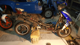
Anyways, I need a project and thought I'd convert one to electric.
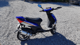
I already have the scooter : 50cc chinese in good nick but with an annoying oil leak and intermittent spark problem.

My thoughts so far :
a 3Kw mid-mount AC or BLDC motor and compatible controller
a 72V LiPo battery pack - 20S8P (2Kw - can add to this later if required)
a small 12V LiPo battery pack for ignition / start-up etc
a 72/12V converter to charging the 12V LiPo pack and supplying lights and horn etc
a pair of SSR contactor(s) - 1 hi-voltage (72V) and 1 x lo-voltage (12V)

a similar acceleration & top speed (better if poss. but no worse)
20Km+ range / autonomy (with the internal 2Kw pack)
an onboard charger (4 to 5 hour charge period)
provision for an additional 2Kw of LiPo (increase range to around 40Km)

I intend to keep chassis / original equipment mods to a bare minimum - except the switch from ICE to electric and I'd like to think that as many decisions as possible will be based upon maintaining DIY simplicity / transfer to other makes of scooter. I don't really know the implications re: re-licencing / MOT / TuV but believe it to be pretty simple (having spoken to the DVLA) in the UK. In France, it's most impossible (currently) but everyone 'upgrades' their 50cc 'scoots' and no-one blinks an eye. No idea about the Netherlands and further afield.

The 'donor' scooter is to be the 'el-cheapo' Chinese RPS scooter in great nick, the parts could always be sold on - if I can find a buyer.
I'd like to think that 800 - 1000 Euro would do the trick. Considering the current London ULEZ charges (12£50/day) this would equate to a 3 - 4 month (5 days a week) reclaim period... seems pretty reasonable IF it can be done...

I'm thinking of documenting the whole project with a view to enabling others to copy... I'm most deffinitely not a You-Tuber but I could update the forum with progress and even make a website for posterity ;)

Does this sound feasible ? Any ideas / advice / thoughts ?
 
With a 2.2Kwh of battery I can get ~45Km so I don't think you'll need a bigger battery.

Having a 12V Battery is good for redundancy, I just carry a second 72V-12V converter with me in case the current one fails.

Here is a motor I can suggest for the conversion:
http://www.eastgem.net/da90-k1.html
http://www.eastgem.net/accsesories.html
It already has the slotted axle that can take standard sprockets.
 
Hi eee291,
Thanks for the message.
That's a great range and indicates circa 50W / Km. My calculations / reasearch had put me at about 100W/Km !
What ride are you running ?
What power motor are you using ?
At what speed do you get the 45Km ?
I ask because I'm really keen to keep the scooter I have 'attractive' in that I'd like it to be *at least* as fast as the original; 45KmH. I need to keep my son and his mates 'interested'... :D

Thanks in advance. I'm off to gen-up on your links !
 
It has a 3Kw hub motor with a 5Kw Controller, range was 45Km at ~50km/h. Top speed was about 70Km/h limited to 54 now since my little brother was caught doing 60, ended up paying 240€. 70€ for speeding and 170€ because it was registered on my name. :cry:
From what I read online 40-45Wh/km is pretty standard for a 45Km/h scooter

Currently I'm converting a Derbi Senda SM. It's going real slow right now but specs will be something like 18Kw peak motor, (24S2P) 4.4Kwh Battery and
a 2-3.6Kw charger on board.
 
Aha... Brilliant info. Thanks.
Dunno how I calculated the 100W/Km :oops: but it matters not - I prefer your 50W/Km !! :D
We just bought our son (15yrs old) an old Reiju 50cc (very similar to your Derbi) and, when the scoot is completed, that's to be the next candidate (or something similar if he won't let me play with the Reiju) which should benefit from the scoot's learning curve :twisted:

I'll post some pics of my work as I go...
 

Attachments

  • Scooter (Arrival)(500x281px).png
    Scooter (Arrival)(500x281px).png
    114.2 KB · Views: 3,347
Always nice to see conversions from ICE to electric.
The biggest problem with an ICE scooter like the one you want to convert is the friction based CVT belt system. It is not wise to only replace the ICE engine and keep the CVT system in place. It is very inefficient and will eat a lot of power. So then the 100Wh/km will be more likely.
That's why factory made electric scooters mostly have a hub motor rear wheel. If you want to use a hub motor rear wheel you'll have to fabricate a swing arm. Or you can use the existing casing and replace the CVT belt system for a fixed gearing using chain and sprockets (or a belt and pulley's). Then you can use a mid motor in place of the ICE engine.
 
Hi SlowCo.
Thanks for your message. I'm with you re: the CVT belt drive. I 'm leaning towards a chain / sprocket arrangement and am currently thinking of a 17:11 sprocket set-up; the 17 up front, on the motor, and the 11 back aft.
I think this should allow a 5000rpm mid-mount motor to drive the rear wheel (T8F shaft), through the swing-arm gearbox (14:1 reduction that I can't figure out how to effectively, and not too expensively, remove ! ) at around 57Kph (max). I can always increase the rear / decrease the front pinion(s) to adjust the final acceleration / speed. (17:13 would provide a lower top speed but better acceleration... )
The 'downside' with this, as I currently see it, will be chain/sprocket noise (compared to belt), no clutch / inability to freewheel when pushing the scoot and any soft-start restrictions placed upon me by the motor controller itself. I don't see any of these as 'deal-breakers' - just stuff I'll need to overcome.
You're right too about a hub motor option. I thought about this long and hard but found trying to match a hub motor to the swingarm gearbox o/p shaft and replacing the existing internal rear drum brake with a different set-up to be too invasive and too 'scoot'-specific; I felt each 'scoot' make/model would require specific-to-'scoot' instructions and post-conversion certification may well be harder should the swingarm and rear brake ass'y have been changed too much. The chain/sprocket method seems to negate major structural changes... but I may well yet be wrong (often am ! ) and wish I'd chosen a different path... time will tell...
As I said, the idea for me is to try and keep the whole conversion within the realms of a DIY-er and the cost sub-1000€ so that anyone with a 'dirty' scooter could convert to electric pretty quickly and within a tight budget thereby (from my point of view) making it more attractive.

Anyways, in frustration and wishing to 'get on', I ordered a 3Kw Kunray BLDC motor/controller unit over the weekend. I hope I won't live to regret my inclusiveness!!
I've also started getting things together to build my Li-Po battery packs. Currently looking at a pair of 1Kw packs 20S4P configuration...

I'll post some pics as I go and no doubt will be back asking for help :confused:

Thanks again.
 
ee291

I was thinking about your Derbi Senda :mrgreen:

Currently I'm converting a Derbi Senda SM. It's going real slow right now but specs will be something like 18Kw peak motor, (24S2P) 4.4Kwh Battery and
a 2-3.6Kw charger on board.

Please excuse my questions : Super interesed and rather envious; I wish I'd started with a non-scoot although it is (for me) a very interesting project and not too expensive to start-off with.
Is it pretty simple to register a converted bike where you live ?
Do you have a thread I can follow ?
Best of luck and hope your build speeds up for you.
 
3DRoboGuy said:
ee291

I was thinking about your Derbi Senda :mrgreen:

Currently I'm converting a Derbi Senda SM. It's going real slow right now but specs will be something like 18Kw peak motor, (24S2P) 4.4Kwh Battery and
a 2-3.6Kw charger on board.

Please excuse my questions : Super interesed and rather envious; I wish I'd started with a non-scoot although it is (for me) a very interesting project and not too expensive to start-off with.
Is it pretty simple to register a converted bike where you live ?
Do you have a thread I can follow ?
Best of luck and hope your build speeds up for you.

The Derbi is still stock, I just bought Controller,Motor,Battery etc. I could pretty much start right now but I'm still waiting on someone.

The registration won't be hard but it will be expensive! Anywhere from 450€-750€ (depending on how far I'm willing to travel) for the paperwork excluding registration which could be another 180€ if I have to re-register it.
Cost for parts so far were about 1500€ excluding the Derbi.

Apparently it is really cheap in some states here to get a scooter registered. I saw a guy take a Mach1 sitting scooter and registered it as a 50cc equivalent scooter, all he had to do was add some indicators and wear a helmet. Cost him like 80€
 
3DRoboGuy said:
Anyways, in frustration and wishing to 'get on', I ordered a 3Kw Kunray BLDC motor/controller unit over the weekend. I hope I won't live to regret my inclusiveness!!
I've also started getting things together to build my Li-Po battery packs. Currently looking at a pair of 1Kw packs 20S4P configuration...

I'll post some pics as I go and no doubt will be back asking for help :confused:

Thanks again.

Hi 3DRoboGuy, i'm buying the same motor and controller with 72v 20s1p lipo pack for my drift trike.

Super keen to see how your build goes and wondering what kind of charger you decided on?
 
3DRoboGuy said:
Hi,
First time on the forum, so introductions first :

Does this sound feasible ? Any ideas / advice / thoughts ?

Sounds like a sweet project.
But you said that you are living in France. And as far as I know, regulations are pretty harsh for DIY vehicles there.
I think that might be the biggest difficulty in the build you plan. You really need to dig into that part.

Technically speaking it won't be too hard to build an electric scooter capable of over performing a 50cc. Since you already purchased the bike I think that an inboard motor is probably the easiest solution, unless you can easily install a swingarm for a hub motor in which case go for it, hub motors are awesome for scooters.
If it was my build and given your target range of only 20km, I would probably keep the transmission, or at least I would experiment with it first and then, later, maybe go for a chain instead if it turns out to be problematic. Sure you lose a bit of efficiency, but you gain starting torque and/or max speed so in the end it might be interesting. Efficiency is for people who need a lot of range, doing 20 or 30km is really no problem.

I don't know much about inboard motors so I can't help with the specifics about battery size, controller or motors here, but if I had to guess I'd say that a 3-4000W motor should be plenty enough, but plan for a very good battery and try to fit as many Ah as you can while keeping the voltage at 72V minimum. Regarding autonomy, well it totally depends on riding style but generally speaking for a scooter with a hub motor, my experience is that 1Ah of battery capacity = 1km of distance, if you ride it hard. So in your case, doing 20km might be doable with 20Ah. But then your discharge rate might be too high for your cells so you will probably have to go for 30 or even 40Ah.
Forget about the 12V battery, doesn't really worth the cost, complication, weight, reliability issues... any DC/DC converter will do the job efficiently enough and you generally don't have a lot of stuff to power aside from the front lights. Just buy a good, overpowered one (for example if you need 3 amps, purchase a DCDC converter capable of 6 Amps or more). I did that on all my builds and so far I never blew a single one. And even if the 12V converter fails, you can still ride home and change it later, most good controllers don't need it at all. Keep that precious space for your main battery, you will need to draw a lot of amps from it so it needs to be big.

I'd forget about LiPo, they are harder to maintain, they don't last long and they are delicate. If your scooter is intended for a kid it will have to be tough and withstand a lot of abuse, go for an other chemistry who can provide you with high continuous or burst discharge currents and last longer.

Also, I think that 1000Euro will be short for such a build in France. That would be the price for me in China, but everything is way cheaper here. In my opinion you can easily double that.
 
3DRoboGuy said:
Anyways, in frustration and wishing to 'get on', I ordered a 3Kw Kunray BLDC motor/controller unit over the weekend. I hope I won't live to regret my inclusiveness!!

That seems way underpowered to me!
50A controllers is barely what they put here on lightweight granny scooters.
 
Hi Bikegirl,
Thanks. Sounds even more interesting too !
Here's where I am at the moment; stripped down and ready for some electric kit !

<EDIT>
I forgot : I decided (just before the last post :oops: ) to go for a 5A unit - simply because I was trying to keep costs down !
To be fair, a 10A would be the max for my chosen battery type / pack size and is now on order too (I am making my batteries so have a little cash to spare).

I'll let you know how I get on with the 5A version - it arrived this week - and I'm pretty much finished with my battery building so will try it out later this coming week. :)
 

Attachments

  • Scoot stripped-SideOn(512x288px).png
    Scoot stripped-SideOn(512x288px).png
    90.2 KB · Views: 3,138
Hi Dui, ni shuo de dui,
Unfortunately the max power allowed in France is 3Kw / 4.5Hp and I am trying to keep the scoot as close to original / 'in spec' as possible for minimum re-approval hassle. Additionally... it is only for a 15 - 16 year old so 50Kmh would be acceptable, 60Kmh would be (for legality) WAY over the top but, from my calculations, should be possible.
Originally, I was looking at a 5Kw unit but, the same sort of calculations, seemed to indicate I'd need a bigger battery pack = more space...

In the end I decided to remain boring... 3Kw... 72V 2Kw battery pack :)

Technical re-licencing (homologation) issues in France ARE really impossible but, like I say, most kids / families modify their kit anyways... So I'm not going to 'bother' too much about this right now. This is, though, one of the reasons I'm trying to keep the spec as close to original as possible.

I'll let you know how I get on with it...
 
Time for an update ! I've made some progress with the motor :
The motor controller arrived !! Yaaay !!!
BLDC Motor-KR3Kw72V(250x212px).png
Initially, I removed the cylinder head. Once that was done, the swingarm was next. I found it easier to leave the swingarm attached to the scoot for the major kit removal as it helped support and hold the crankcase etc during the work. So, after the cylinder head, it was the turn of the oil pump, the starter motor and the ignition system.
I'll need to design some covers / blanks for the holes. I intend to route the motor cables through the square, oil pump hole so will make a blank specifically for that purpose.
View attachment 11
Once the cylinder head, oil pump, starter motor and ignition system were removed I began to 'play' with possible motor positions; the crankshaft was 'annoying' me though - it seemed to always be in the way and I knew it'd have to come out for re-working or... something...
CrankShaft+Starter(250x445px).png
I tried all sorts of ways to remove the crankshaft... and couldn't... In the end, I used a trolley jack - I tried but couldn't move it any other way. The trolley jack did the job in a couple of minutes - live and learn, I guess !
CrankShaft-Removal2(250x445px).png
The swingarm was placed, upside-down, on the trolley jack and 'tied' down with tie-straps all the way around the outside of the jack. The crank shaft was located centre of the trolley jack 'saddle'. The jack was slowly and pressurised, the 'saddle' extended BUT the swingarm itself was restrained by the tie-straps. Slowly, very slowly, being careful so as not to distort the swingarm itself, the crank shaft popped out - as per the centre image above. The whole lot was then cleaned up.

There simply wasn't enough space to mount the motor within the engine casing - even if I had the mind to attempt it ! Looking at the various 3Kw motors available I don't think I can get one much smaller regardless of the amount I'd be willing to pay and even then, the mechanical / machine shop re-work would be extensive (and, therefore, expensive !). In the end I began to see that the motor could be mounted in lieu of the cylinder head if I designed a suitable bracket. Out came Sketchup
Motor+Bracket DesignFront(250x211px).png
Motor+Bracket DesignRear(250x202px).png
and then the 3D printer and in an afternoon I had an ABS bracket knocked up (in pieces - much as I would eventually need in aluminium) and welded them together with an acetone/ABS slurry. Effective !
Motor Bracket Template(250x310px).png Motor bracket ABS with Motor-1(250x445px).png Motor bracket ABS with Motor-2(250x445px).png

Once I'd determined that the the bracket was correct for the motor, I went about mounting it to the 4 threaded holes vacated by the cylinder head studs - all the time being very careful not to break my template ! And, once I'd done that and noted the correct positions of the 4 x slots in the back panel for the new cylinder head machine screws. I say 'slots' - these are 4 x horizontal 20mm x 5mm slots allowing the bracket to be mounted to the crank case in a way that there would be 20mm +/- of lateral movement to enable future alignment of the motor pinion with the rear, gearbox, sprocket.
I then cut out and welded the same pieces all over again BUT, this time, in some 'scrap' 5mm aluminium I re-tasked from the skip at the local scrapyard.
Now I had something like the images below. I actually began to feel pretty pleased with myself... starting to believe the whole crazy idea might just work !!
Motor bracket offered-up(250x445px).png Motor Bracket Alu((250x445px).png Motor attached-1(250x445px).png
The three holes in the bottom strengthener / spacer are to enable any water to drain more easily.
The motor is held rigid by the two pivot bolts at the bottom bracket and then the short arm at the rear of the motor (left hand side in the images) to help prevent twisting. The long arm on the top of the bracket, at the pinion / drive side of the motor allows the whole motor to rotate forwards / backwards (in relation to the scoot) and thereby enable the chain to be tensioned - much like an alternator adjuster-arm.
To be fair, after a wee bit of filing some rough edges, the whole system mounted up in 15 minutes
Motor + SwingArm(250x141px).png Motor-InPlace(250x203px).png
My job with the motor was almost done. All I had to do now was blank off the old / no longer used crankcase holes for the starter motor, crank shaft and oil pump etc being careful to route the motor cables through the now empty, crankcase and up towards the back of the scoot where I planned the electrics & controller would go !

Next is the Gearing, tidying up the electrics and batteries...
 
An update re: my (rather hopeful?) gearing...

I'm not sure this will work (given the gearing) but I have to start someplace !
I figure that it will be easier if I can the existing rear variator / clutch assembly (in some modified manner) to pass the drive through the gearbox to the rear wheel. I'm hoping the clutch / gearbox will be beneficial / not pose any significant problems... although some math with the ratios indicates a top speed of 11kph !! Hmm... To be frank, I think I'm going to need to re-visit this one BUT, at the current time using the existing variator / clutch assembly is the easiest way to get drive into the gearbox... I certainly can't see any way at all (bar a hub motor) of 'ignoring' or bypassing the gearbox - although I have looked at switching gear ratios within it (costly and of (at first glance) limited benefit !

So, to make a start and fit the new sprocket to the rear clutch ass'y, I stripped down the whole assembly and through-welded the sprocket to the two clutch plates (they will not be needed as the rear section of the variator anymore so...
Gearing-1 disassembled(250x126).png

I started by removing the nut from the splined gearbox input shaft. The clutch bell housing (right hand side in the image above) may then be removed, followed by the variator itself.
A large nut will be visible once the bell housing is removed. If you're planning on doing this yourself, then be VERY careful stripping the variator - it's under pressure from an internal spring (image below). I held the variator plates shut (their natural position under spring tension) and removed the large nut. In doing so the spring tries to release - keep that pressure applied, remove the nut fully and all comes apart as per the next image.
Gearing-1 spacer ready-to-weld(250x141px).png

I then stripped the variator guide plates from the shaft and welded the 69tooth sprocket to both plates. To ensure the new sprocket remained central / true I made up a plastic spacer (again, using Sketchup and the 3D printer).
Gearing-1 welded(250x238px).png

Reassembly was the opposite of disassembly (above) - apply pressure to the spring and start the nut off on its thread. Lock up the nut and refit the whole assembly to the gearbox input shaft.
Gearing-1 re-fitted-1(250x445px).png

If I find (as I'm pretty sure I will) that the clutch assembly is just too inefficient / isn't needed then I can always lock the clutch. I can also lengthen the gearing somewhat...
But... that's for another day !
 
Hi eee291,
I just LOVE the look of those JetForce scooters !
I guess they're both using Revolt motors - neat. I was too much of a cheapskate and limited myself to 200Euro of 3Kw BLDC. Look very similar in size, though the Revolts have (at least) double the power at the same voltage (I've gone with 72V).
I think I've alreay said it, but I may live to regret my stinginess wrt the motor/controller... we'll see. . .
 
Next came the original / as-fitted electrics and their sorting out and tidying up.
Once again, like the strip down, this was pretty straight forward. Unfortunately, the Chinese used a strip, twist, solder and tape method of making joints within the wiring loom. They also had multiple earth / ground connections (using the strip, twist, solder and tape method) which in turn connected at both ends of a common (green) wire to the chassis. None too neat or pleasant to work with and definitely not simple to fault find. The cause of the intermittent spark did become apparent though - just a little too late for this ol' scoot !!
Electrics_TidyUp3(250x445px).png

All the 'strip, twist, solder and tape' -type joints were removed and each item was individually tidied up. In all cases (there's not a lot of current involved here and it's all 12V) the earth cables were directed back aft to a common earth bolt.
Electrics-TidyUp1(250x445px).png

Once the cable loom had been opened up it became possible to begin removing cables; the battery cables first, then the ignition and charge system (c/w CDI and regulator)...
At the end of an hour all that was left was lighting, ignition, side-stand down, fuel gauge, starter, kill switch and low oil cables.

The 'kill' switch was modified (with an additional cable) from connecting the low-tension side of the spark ignition system to earth (thereby killing the spark) to being a pass through switch intended as an interlock for the controller/motor HV relays.
Kill-Enable switch re-task-1(250x445px).png

The fuel gauge cable was isolated as was the low oil level cable. These will be re-tasked later.
The idea is (once the scoot is 'up and running') to re-task the :
[1] low oil (red) warning lamp to be a low Voltage lamp (something like, 72V battery pack below 65V)
[2] the fuel gauge cable (full scale deflection at 0V / connected to ground/earth) to indicate battery pack voltage and, therefore, a kind of battery level indicator. An AVR Tiny will be used to pulse the gauge at a preset rate depending upon the battery voltage it detects (thereby adjusting gauge needle deflection)... Crude... but I don't like unused controls / gauges and it would be a helpful indicator whilst employing the existing panel gauge. An improvement may be to switch out the programming of the AVR to be a coulomb counter and, therefore, make it MUCH for useful... we'll see... that's a later-date project !

I have a made a small 12V Li-Ion pack (Panasonic 18650 cells again) (which will be charged by the DCDC convertor) and used to 'power' the ignition switch, via the modified 'kill' switch, and thereby energise the Controller <Enable> line and two (one HV/72V and one LV/12V) relays / contactors or, in my case SSRs (solid state relays).

All lights have been switched out for low-power LEDS, including the head light (VASTLY improved over the original headlight). The only challenge here was the standard method of earthing the indicators was 'novel' in that the Chinese manufacturer used the instrument panel indicator 'On' tell-tale as a ground for the active ones. Due to the extremely low power required by LEDs, this simply meant that ALL indicators flash when either direction is selected. The way I chose to work around this was to trace the two, left/right, indicator cables at the panel tell-tale and insert standard 1N4001 diodes into each. This way one indicator direction cannot back-feed the other. Hey-presto - all LEDs including panel lights.

Finally the new 'loom' was routed through some braided sleeving with cables exiting at their required points along the route.
Electrics_TidiedUp1(250x445px).png

Now onto the main EV electrics !!!
 
I thought that before I start the main / primary EV electrics I should 'tidy up' a little bit first.
To be fair, at this precise time, given that I have serious doubts as to the effectiveness (and, therefore, finality) of the scoots gearing, I have decided to carry out the most basic of tunnel / cover modifications. All I did was to mark out the upper and lower limits of the chain drive between the motor sprocket and the, recently refitted, rear gearbox input sprocket
SwingarmCover_MarkingOut(250x141px).png

and then cut the marked area out with a hacksaw and file. A little sandpaper on the edges to finish and...
SwingarmCover_CutOut(250x445px).png

Once the marker pen is cleared off with some white-spirit then all will be well for a proper, chain-on test...
SwingarmCover_ModifiedOpenedUp-Gearing1(250x141px).png
SwingarmCover_ModifiedOfferedUp(250x141px).png
 
These are to protect the internals form dirt, grit and water ingress as far as practically possible. In the case of my scoot, I have various cover / blank plates to design and fit :
[1] Oil pump blanks (I need to design one with a cable (motor) pass-through slot)
[2] Starter motor blank
[3] Crank shaft blanks
I reverted back to SketchUp again and then the 3D printer and came up with these which I then fitted:
Blanks(250x268px).png

Once designed and printed (yellow ABS) I trial fitted. Just the second iteration of the square oil pump blank to take the motor cable...
Blanks_OilPumpFitted(250x141px).png

and then the others...
Blanks_CrankShaftFitted(250x141px).pngBlanks_StarterFitted(250x445px).png
 
With most of the 'boring' stuff out of the way I started off trying to work out where to site the batteries I would be making. Once the site was chosen I'd have a better idea as to final available / required dimensions. I had already played about with weights etc and pre-set any pre-requirements I had :
[1] they must be removable for security, off-scoot charging and protection against extreme temperatures.
[2] being removable they need to be pretty light - around older laptop weights; 1Kg (plus or minus) would be great. For me 'lighter' not only means more easily carried about but less likely to be thumped around when placing them down etc and more manoeuvrable getting them on-off / in-out of the scoot.
[3] two (or more) smaller packs would tend to suit the previous requirements whilst benefitting from more spaces on board the scoot (there seems to me to be a lot of 'small' spaces available but few large ones) and also lends them more readily to be re-tasked between projects.
[4] maintain as-low-as-possible a centre of gravity; a top heavy scoot is horrible to handle both in traffic and whilst re-positioning/parking it by hand
[5] if at all possible, maintain the helmet area below the seat. Having said that, on this scoot any helmet would have to be a pretty small open face or half helmet if it were to fit at all !

Anyways, I had already selected 72V : 13-14AHr per pack equating to a 20S4P (1Kw) minimum pack power / size. Each pack was to be thermally protected and be able to be individually and / or group charged.

From the outset, I had hoped to build two 'long and slim' (20 cells long, 4 cells wide) packs and site them under the riders' feet, within the fairing area. Unfortunately, without massive frame mods, there simply wasn't enough space for this to be feasible.
Battery_MockUps(250x141px).png

Next I looked at using the space vacated by the recently removed fuel tank (although, in reality, too high - from a centre of gravity point of view.). The main (and pretty much insurmountable) problem here though, was that the seat lock bracket was in the way; the two packs would fit (side-by-side) but they'd not be removable. That coupled with the height 'issue' meant option 2 was, again without major grinding and welding work, a dead end too !!
Then I looked at designing and building two exhaust-style 'cans' - one for each of the battery packs and either side of the scoot... a wee bit drastic but definitely worth investigating. Maybe at a later date.
In the end I decided to fit them directly above the motor; in the area below the seat, at the very bottom of the seat 'box'. It would mean removing much of the base of the seat-box - so that they could be taken out (for in-house / external charging) and put back in again - but this was the most feasible of the options I'd looked at...
Once I had the location sorted it came time to make a bracket/shelf arrangement for the two battery packs to sit in above the motor. Initially, I made a mockup in cardboard then in some left-over 10mm EPA foam that was lying around. Once that seemed to be OK, I re-made the bracket so that the original would fit inside it, removed the original and fibreglassed up a shelf unit complete with side and fixing points to locate it securely on the scoot framework whilst, at the same time ensuring the sufficient room for the motor to be rotated for chain tensioning... A bit for sanding and painting and...
GRP Battery Tray_Mould(250x141px).png

With the battery mock-ups now fitting snugly in their new 'home' on board the scoot I gingerly cut, re-cut and cut again (and again - little by little) the base of the under-seat helmet / storage box to allow their insertion and removal. That all done, it was time to move on to making the battery packs.After gathering together the parts; NCR18650GA batteries, SplitPort BMS, Thermal CB, Charge Plug/Socket & Anderson connector, I began, with the help of the Spot Welder I built for these 18650 cells, SketchUp and my 3D Printer to build the battery packs.

I ended up :
...Building the packs - 20S4P configuration...
I decided to spot-weld (not solder) and fuse the cells (top and bottom / anode and cathode). I also decided to go with a split-port BMS and a thermal, 50A circuit breaker for output protection.
Battery 20S4P Thermistors(250x141px).png

I designed in 2 x thermistors and placed them 1/3 of the way / 6 cells rows in from each end-cap. The cables were routed to the CB end-cap and left insulated for a future date add-on project. The idea being to enable battery cooling / heating during charging and battery cooling when running and too hot. I haven't gotten round to this just yet but, when I need a break, I am programming and testing the AVR code.)

...Printing out, building and connecting up the end caps...
Battery-20S4P_OpenedReadyToHeatShrink(250x141px).png
Battery-20S4P_EndCapConnections(250x141px).png

(I designed the end caps with three ridges - for the heat shrink to grip onto)
...and putting them all together before applying 3mm foam protective sheet and heatshrinking the lot...
Battery 20S4P CB End Cap(250x444px).png

NCR18650GA cells are 'C' rated at 3340mAHr. 'C' effectively equates to capacity (measured in AmpHours).
In the packs (designed & built above) there are 4 x NCR18650GA cells in parallel. That produces a total of (just over) 13AHr. They are rated at 3C continuous (10C max) designed discharge and 0.7C designed charge current which equates to a 9A charge current PER battery pack, therefore, a 10AHr charger would be fine (seeing as a 9Ahr charger isn't readily available and 1 additional AHr shouldn't cause an issue) for these packs.
Furthermore, whilst each pack has a 'C' rating of (just over) 9AHr, the PAIR of packs onboard the scoot will have a 'C' rating of (just over) 18AHr, so a 20A charger COULD be used IF the battery packs were to be charged as a pair (with a similar caution as per the 10AHr charger for a single pack).
I purchased (quite a while ago) a 72v 5AHr charger, however, should I wish to install an onboard (on the scoot) charger than to minimise charge time a 20AHr unit would quadruple the available charge current and (a little simplistically) speed up the re-charge time accordingly - if the room is available at the end of the project.
Either way, I don't foresee an immediate need to have 'high speed' charging and intend (at this point in time) to use the 5AHr charger for both onboard (dual / paired pack)and in-house (single pack) charging. As as 'aside' the 5A charger I purchased was $60 (USD) whereas a 20A version would be around $160 (USD) - not a huge increase for a far quicker re-charge - if required. The real 'downside' is :
the 5A charger comes in at around 1Kg and has dimensions around 200mm x 110mm x 60mm
whereas
the 20A version comes in at around 3+Kg and a ballpark size of 330mm x 175mm x 115mm.
Finding enough room for the 20A charger onboard the scoot would be much more difficult - in my case ! At some point I'll do a more in-depth study and comparison of 5A, 10A, 15A and 20A chargers... but not today... I'm still on a mission to finish this scoot !
 
Back
Top