
You are using an out of date browser. It may not display this or other websites correctly.
You should upgrade or use an alternative browser.
You should upgrade or use an alternative browser.
Axiom: a 100kW+ motor controller
- Thread starter marcos
- Start date
marcos
1 kW
- Joined
- Nov 19, 2016
- Messages
- 348
Its a good chip but the eval board lacks the isolated DC/DC to send power across the isolation.Hackey said:Hey marcos
Please have a look at these driver board and update if i can use this.
http://www.ti.com/lit/ug/sllu207a/sllu207a.pdf
marcos
1 kW
- Joined
- Nov 19, 2016
- Messages
- 348
We are ready to release the Axiom datasheet!
Next Monday all our subscribers will have access to the datasheet through our newsletter.
To subscribe to the newsletter, sign up here!
http://www.powerdesigns.ca/newsletter/
It will be only available to the subscribers for quite a while until we let the file publicly available for download.
Important announcements will happen there as well, so we hope to see you guys in the list.
FYI I subscribed some people that explicitly asked to be kept updated, and people that are using our boards.
And btw, Axiom is the clear leader in hackaday prize popularity so far, woot!
Cheers!
marcos
1 kW
- Joined
- Nov 19, 2016
- Messages
- 348
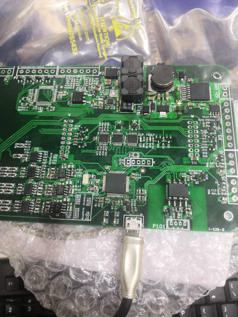
I have to say I'm terrified about the outcome of this, the board looks assembled with a soldering pen a instead of reflow soldered, the only way I could replace that mosfet is reflowing the whole board (probably twice). A solder blob or cold joint in the control IC could have made the mosfet to blow. Also check the polarities of all the diodes and tvs.Hackey said:I am close.
Mosfet for 24v side came faulty so ordered the replacement now.
Can i use any other mosfet for temperory replacement. What should be minimum voltage rating for that mosfet.
No, you shouldn't use any other mosfet, I can't assure it will work. I spent an hour looking for a replacement when the original part used in the simulations were non stocked.
By default the board provides 24V, but you need to check if thats the voltage your gate driver needs. Axiom uses 15V for example.
Hackey
1 W
- Joined
- Dec 20, 2018
- Messages
- 51
I am using same gate drivers you used. How can i supply 16v to board can i use seperate buck boost converter for this.marcos said:I have to say I'm terrified about the outcome of this, the board looks assembled with a soldering pen a instead of reflow soldered, the only way I could replace that mosfet is reflowing the whole board (probably twice). A solder blob or cold joint in the control IC could have made the mosfet to blow. Also check the polarities of all the diodes and tvs.Hackey said:I am close.
Mosfet for 24v side came faulty so ordered the replacement now.
Can i use any other mosfet for temperory replacement. What should be minimum voltage rating for that mosfet.
No, you shouldn't use any other mosfet, I can't assure it will work. I spent an hour looking for a replacement when the original part used in the simulations were non stocked.
By default the board provides 24V, but you need to check if thats the voltage your gate driver needs. Axiom uses 15V for example.
Mosfet came shorted from digikey i checked it beforehand. I also checked all components and main ic soldering seems preety good and no solder blobs there.
Sent from my COR-AL00 using Tapatalk
marcos
1 kW
- Joined
- Nov 19, 2016
- Messages
- 348
Set R74 to 110kohm for 15V operation.Hackey said:I am using same gate drivers you used. How can i supply 16v to board can i use seperate buck boost converter for this.
Beware your ESD countermeasures, its unlikely that digikey will send you a damaged part.
marcos
1 kW
- Joined
- Nov 19, 2016
- Messages
- 348
We have a lot of math developed around this controller to calculate gains, tolerances, trips, cutoffs, and errors, but that is not open source, its there to help our customers and speed up our consultancy work.Hackey said:How to calculate current gain of current sensors.
HASS-400-S
And after making all connections fault light is staying on. What could be issue.
You could find this line helpful though.
With that older board you need to add this to hw_axiom.h:
#define HW_PALTA_REV_B
Hackey
1 W
- Joined
- Dec 20, 2018
- Messages
- 51
Thanks for the feedback.marcos said:We have a lot of math developed around this controller to calculate gains, tolerances, trips, cutoffs, and errors, but that is not open source, its there to help our customers and speed up our consultancy work.Hackey said:How to calculate current gain of current sensors.
HASS-400-S
And after making all connections fault light is staying on. What could be issue.
You could find this line helpful though.
With that older board you need to add this to hw_axiom.h:
#define HW_PALTA_REV_B
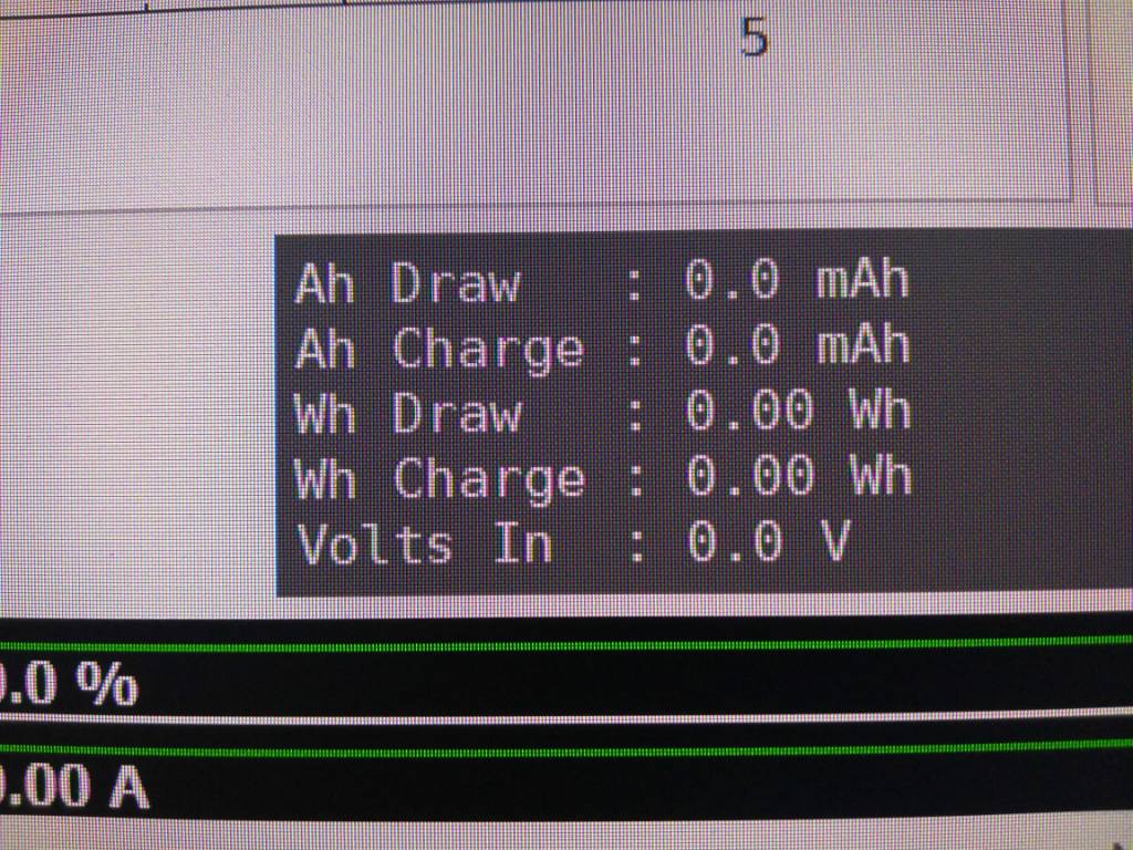
Now my vbus is not measuring any voltage its showing 0.00v.
I am having R22,6,8 as 1Mohm and i have connected battery pack of 20s (75v nominal) i have measured voltage of around 25mV at input of AMC1301 and output of around 1.35 at output . Then i checked opamps and i got around 205mV.
And i also checked the voltage at PC3 pin of stm32 which is same as 205mV.
I have also changed HVDC Transfer function from 185 to 363.63 to compensate for the 3Mohm resistors.
Please suggest some solution.
Sent from my COR-AL00 using Tapatalk
hi ...
I'm still alive ...I don't use high voltage yet )))
I'm still learning how to use whole system ...
My battery is 60 volt maybe it's the problem to pass correct FOC ... Because motor is 36 volt ... ?????
small video my update ...
I apologize for my french video ...
[youtube]https://youtu.be/3FJLdkONhoA[/youtube]
[youtube]https://youtu.be/FOHPWLROhp4[/youtube]
Hackey said:Thanks for the feedback.marcos said:We have a lot of math developed around this controller to calculate gains, tolerances, trips, cutoffs, and errors, but that is not open source, its there to help our customers and speed up our consultancy work.Hackey said:How to calculate current gain of current sensors.
HASS-400-S
And after making all connections fault light is staying on. What could be issue.
You could find this line helpful though.
With that older board you need to add this to hw_axiom.h:
#define HW_PALTA_REV_B
Now my vbus is not measuring any voltage its showing 0.00v.
I am having R22,6,8 as 1Mohm and i have connected battery pack of 20s (75v nominal) i have measured voltage of around 25mV at input of AMC1301 and output of around 1.35 at output . Then i checked opamps and i got around 205mV.
And i also checked the voltage at PC3 pin of stm32 which is same as 205mV.
I have also changed HVDC Transfer function from 185 to 363.63 to compensate for the 3Mohm resistors.
Please suggest some solution.
Sent from my COR-AL00 using Tapatalk
first ... do not connect 2 PCB together ...
you need fixed main PCB bord ...
you need 15 volts ... check page number 6 ...
The on page 6 describes how to solved this problem .
after you see on you multimeter 15v 5v 3.3v on your mayn bord we will proceed to the next quest)))
p.s.also if you want i can help you by video call
marcos
1 kW
- Joined
- Nov 19, 2016
- Messages
- 348
Awesome! Thanks for recording and sharing your feedback! I appreciate the effort of going through all these things. Magnetic bolts screwing the current sensor was definitively not in my troubleshooting list.Abricosvw said:hi ...
I'm still alive ...I don't use high voltage yet )))
I'm still learning how to use whole system ...
My battery is 60 volt maybe it's the problem to pass correct FOC ... Because motor is 36 volt ... ?????
small video my update ...
I apologize for my french video ...
[youtube]3FJLdkONhoA[/youtube]
[youtube]FOHPWLROhp4[/youtube]
Once you start driving more and more current you'll see more artifacts, for example your + and - wires between battery and DC Link will need to run very close together, twisted if you can to decrease the radiated emissions.
Its great that you are regulating 1A current with +/-425A current sensors.
You can try your IPM motor anytime. With the current code you won't use the reluctance torque as MTPA is not yet merged, but that won't stop your motor from spinning strong. Does your motor have a resolver for position feedback, right?
And thanks for helping hackey!
HighHopes
10 kW
- Joined
- Mar 28, 2013
- Messages
- 929
Its great that you are regulating 1A current with +/-425A current sensors.
ditto. that's impressive
Hackey
1 W
- Joined
- Dec 20, 2018
- Messages
- 51
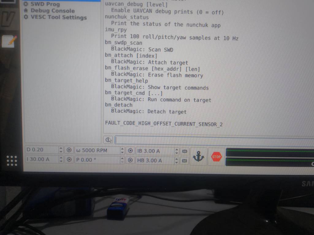
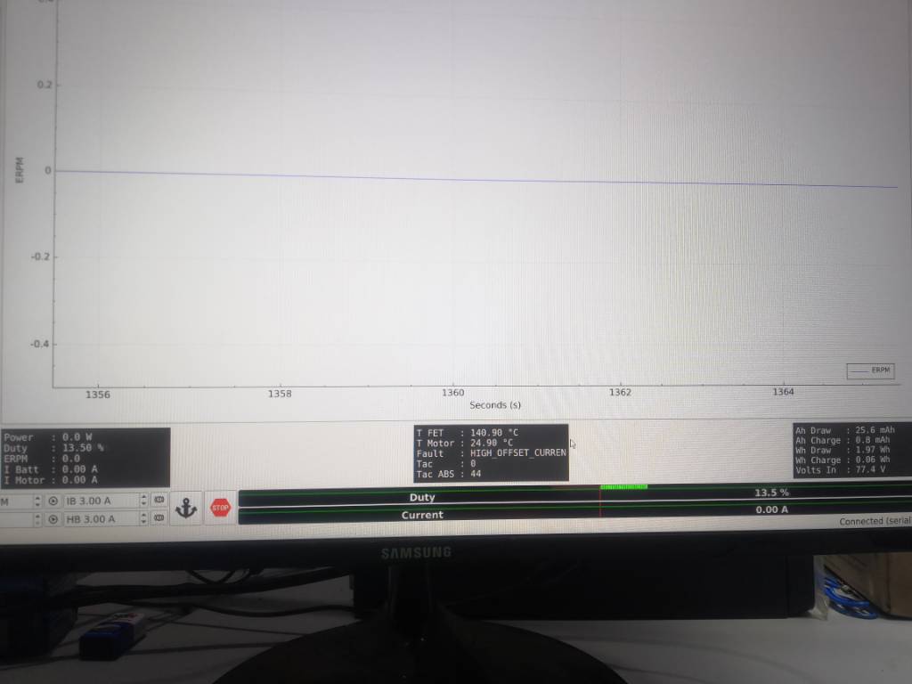
Hey marcos while running foc detection i am unable to measure resistance i can hear knocking sound feom motor i tried various current (10-100amp) levels.
And my igbt temperature is showing 140c while its very cold to touch.
And fault code ( HIGH_OFFSET_CURRENT_SENSOR_2)
I am using 0.00083240 as current sensor gain.
Sent from my COR-AL00 using Tapatalk
And my igbt temperature is showing 140c while its very cold to touch.
And fault code ( HIGH_OFFSET_CURRENT_SENSOR_2)
I am using 0.00083240 as current sensor gain.
Sent from my COR-AL00 using Tapatalk
marcos
1 kW
- Joined
- Nov 19, 2016
- Messages
- 348
Your igbt tenperature sensors are not connected so you shouldn't care about that. If it trips a fault and prevents you running the motor I can code a patch to be able to ignore that sensor.Hackey said:And my igbt temperature is showing 140c while its very cold to touch.
And fault code ( HIGH_OFFSET_CURRENT_SENSOR_2)
I am using 0.00083240 as current sensor gain.
You have a hardware problem with your current sensors. You should measure close to 1.65v at the current sense adc pins. The fault is telling you the signal is far from 1.65V in the current sensor of phase 2 (aka phase B)
Hackey
1 W
- Joined
- Dec 20, 2018
- Messages
- 51
Yo. First successful FOC run complete. Felling so much happy today as i have completed first smd (complicated) project. I have done 320amps continuous for 10min. Igbt's got hot decently. Also please tell me what dead time should i use. Currently using default dead time of vesc.marcos said:Your igbt tenperature sensors are not connected so you shouldn't care about that. If it trips a fault and prevents you running the motor I can code a patch to be able to ignore that sensor.Hackey said:And my igbt temperature is showing 140c while its very cold to touch.
And fault code ( HIGH_OFFSET_CURRENT_SENSOR_2)
I am using 0.00083240 as current sensor gain.
You have a hardware problem with your current sensors. You should measure close to 1.65v at the current sense adc pins. The fault is telling you the signal is far from 1.65V in the current sensor of phase 2 (aka phase B)
Sent from my COR-AL00 using Tapatalk
Hackey
1 W
- Joined
- Dec 20, 2018
- Messages
- 51
Here is link of video: https://youtu.be/goYTHwUFOR0Hackey said:Yo. First successful FOC run complete. Felling so much happy today as i have completed first smd (complicated) project. I have done 320amps continuous for 10min. Igbt's got hot decently. Also please tell me what dead time should i use. Currently using default dead time of vesc.marcos said:Your igbt tenperature sensors are not connected so you shouldn't care about that. If it trips a fault and prevents you running the motor I can code a patch to be able to ignore that sensor.Hackey said:And my igbt temperature is showing 140c while its very cold to touch.
And fault code ( HIGH_OFFSET_CURRENT_SENSOR_2)
I am using 0.00083240 as current sensor gain.
You have a hardware problem with your current sensors. You should measure close to 1.65v at the current sense adc pins. The fault is telling you the signal is far from 1.65V in the current sensor of phase 2 (aka phase B)
Sent from my COR-AL00 using Tapatalk
Thanks a lot Marcos and Abricosvw for guiding me through this project.
Sent from my COR-AL00 using Tapatalk
marcos
1 kW
- Joined
- Nov 19, 2016
- Messages
- 348
Wow, congrats Hackey!!
Are you using motor position feedback (hall/resolver) or is it sensorless?
Here are a few comments:
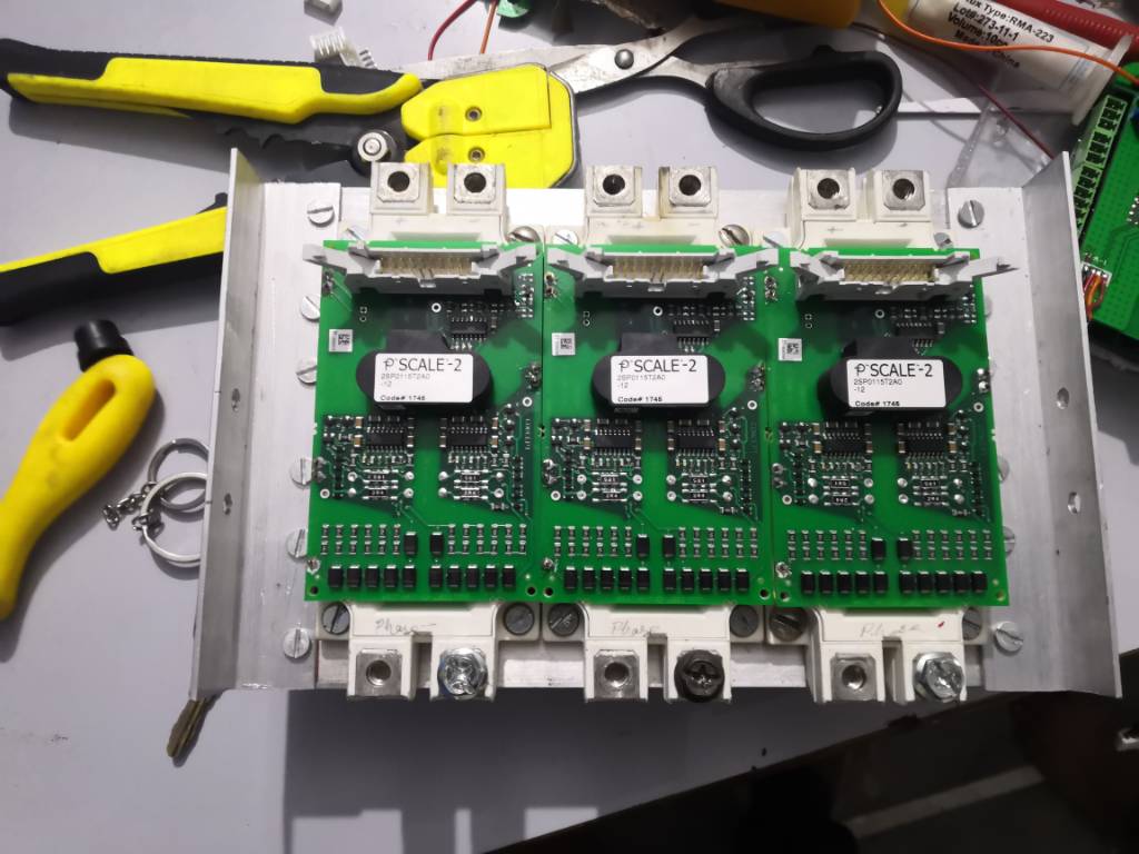
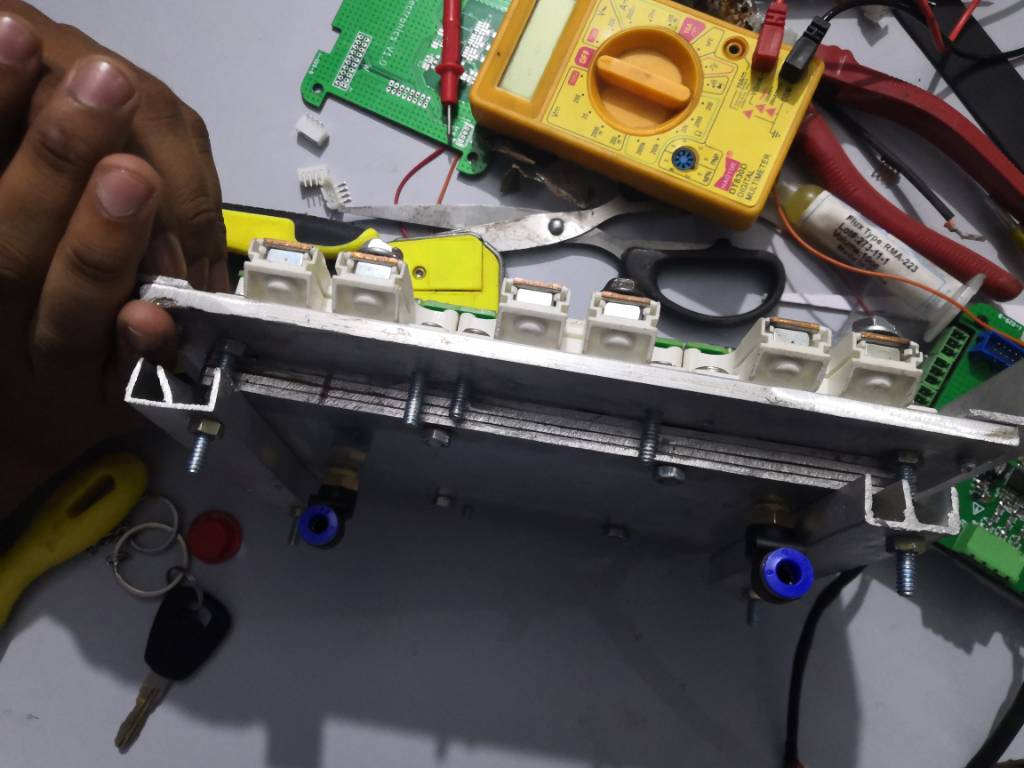
I'm not entirely sure but in the video it looks like the connection between DC Link and IGBTs is not short, and I think one of the IGBT is much further away from the dc link.
That distance creates extra inductance, and inductance creates overshoot during turn off.
Rule of thumb is 10nH per inch.
V=L×di/dt
If you have 60nH, a 700A delta current and the switch happens in 0.1us then you will have 420V of overshoot and likely destroy your IGBT.
Normally you would make a double pulse test to make sure the overshoot is within limits.
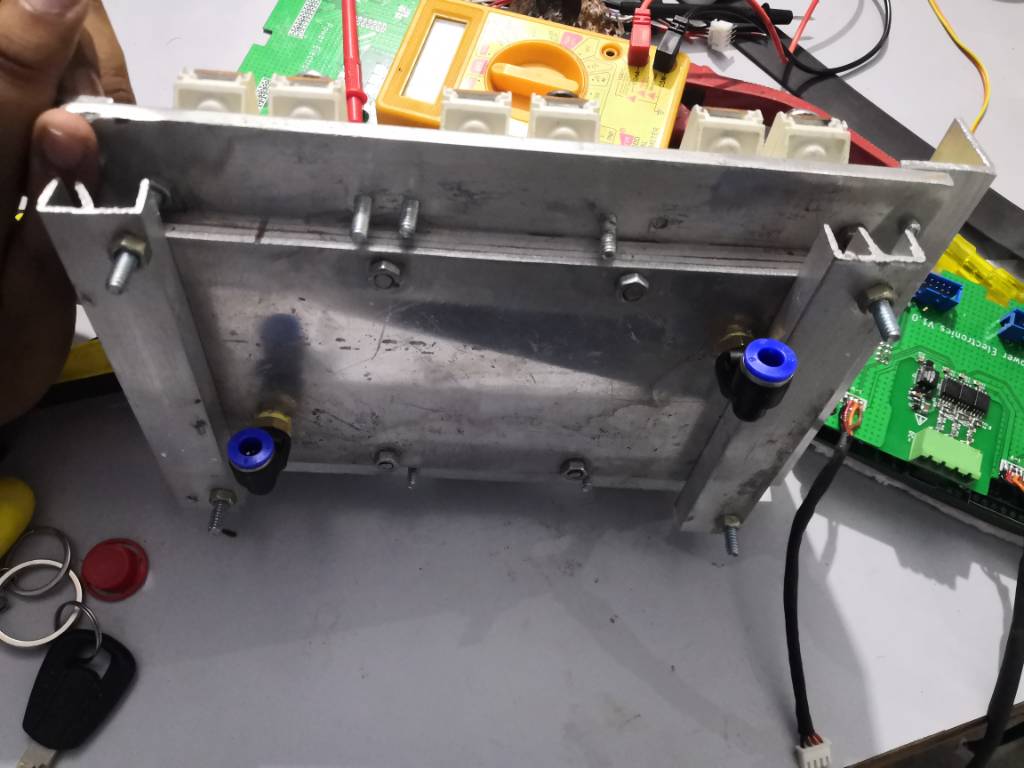
Use the 2 bolts of the IGBT output.
Follow Infineon econodual package mounting instructions, they have notes about torque at the bolts, applying thermal paste, etc.
Keep it up, and watch out, its easy to blow stuff at this power level.
Are you using motor position feedback (hall/resolver) or is it sensorless?
Here are a few comments:
I'm not entirely sure but in the video it looks like the connection between DC Link and IGBTs is not short, and I think one of the IGBT is much further away from the dc link.
That distance creates extra inductance, and inductance creates overshoot during turn off.
Rule of thumb is 10nH per inch.
V=L×di/dt
If you have 60nH, a 700A delta current and the switch happens in 0.1us then you will have 420V of overshoot and likely destroy your IGBT.
Normally you would make a double pulse test to make sure the overshoot is within limits.
Use the 2 bolts of the IGBT output.
Follow Infineon econodual package mounting instructions, they have notes about torque at the bolts, applying thermal paste, etc.
Keep it up, and watch out, its easy to blow stuff at this power level.
Hackey
1 W
- Joined
- Dec 20, 2018
- Messages
- 51
Hey marcos. I am running in sensored(hall sensor). I have adjusted connection between igbt and dc link.marcos said:Wow, congrats Hackey!!
Are you using motor position feedback (hall/resolver) or is it sensorless?
Here are a few comments:
I'm not entirely sure but in the video it looks like the connection between DC Link and IGBTs is not short, and I think one of the IGBT is much further away from the dc link.
That distance creates extra inductance, and inductance creates overshoot during turn off.
Rule of thumb is 10nH per inch.
V=L×di/dt
If you have 60nH, a 700A delta current and the switch happens in 0.1us then you will have 420V of overshoot and likely destroy your IGBT.
Normally you would make a double pulse test to make sure the overshoot is within limits.
Use the 2 bolts of the IGBT output.
Follow Infineon econodual package mounting instructions, they have notes about torque at the bolts, applying thermal paste, etc.
Keep it up, and watch out, its easy to blow stuff at this power level.
I am having problem running in sensorless.
My motor doesn't start it just jerks and on sampling BEMF in sensored mode it is 1volt peak to peak not more than that.
What could be issue
Sent from my COR-AL00 using Tapatalk
Similar threads
- Replies
- 5
- Views
- 387
- Replies
- 1
- Views
- 756
