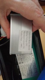
By sticker I'm talking about a printed piece of paper with glue on the back that attaches to the controller that has information on it as to the controllers make, model, and operating parameters.
… so no controller adjustment via display available at all.
"So If I understand correctly you want me to test the black and the purple of this set for voltage, while maneuvering the brakes off and on, is that it?"
Well any black would do, (0vdc, batt ground or negative) but yes.
"There you can see the circuit breaker, but I i used the reset button (strange found it very light /soft on touch) , but no changes..."
You can use the same voltage test as you used with the brake switch to verify. Reading across the breaker, closed is 0vdc, open is the voltage potential of the circuit. Or go from ground to each side, should be the same. Or remove the wires, switch to continuity, testing across the breaker connection spades, looking for no resistance.


")