You are using an out of date browser. It may not display this or other websites correctly.
You should upgrade or use an alternative browser.
You should upgrade or use an alternative browser.
Mongoose DX project
- Thread starter oofnik
- Start date
Could it be that low? I mean, surely there is more torque at the end of the motor shaft than 2.5 Nm...Miles said:Nope. But it looks like they've used the smallest of the CSK series one-way bearings - nominal rating 2.5 Nm.
MitchJi
10 MW
Hi Miles,
That's abysmal. A Rohloff is rated for an input torque of 100 Nm.
Oofnik. If I remember correctly one of the main reasons Matt decided to go with FW's rather than one-ways was concern about the capacity of one-ways. So it might be better, if you can get a reasonable price for boring out a pulley to use a FW.
Also there's a thread (I can find it if you want) in which someone describes a DIY approach for boring out a BCD adaptor (should work with a pulley also) to fit a white FW.
Miles said:Nope. But it looks like they've used the smallest of the CSK series one-way bearings - nominal rating 2.5 Nm.
That's abysmal. A Rohloff is rated for an input torque of 100 Nm.
Oofnik. If I remember correctly one of the main reasons Matt decided to go with FW's rather than one-ways was concern about the capacity of one-ways. So it might be better, if you can get a reasonable price for boring out a pulley to use a FW.
Also there's a thread (I can find it if you want) in which someone describes a DIY approach for boring out a BCD adaptor (should work with a pulley also) to fit a white FW.
oofnik said:Could it be that low? I mean, surely there is more torque at the end of the motor shaft than 2.5 Nm...Miles said:Nope. But it looks like they've used the smallest of the CSK series one-way bearings - nominal rating 2.5 Nm.
Max. continuous torque from the AF 3210 motor is 2.65 Nm. The nominal rating of these one-ways is 50% of peak capacity, I think - so this should cope with the output torque from the motor shaft of the 3210.
MitchJi
10 MW
Hi Miles,
The Velovision Hub Gears review:
http://www.velovision.com/mag/issue29/vv29hubgears.pdf
States:
What am I missing?
The Rohloff can't handle roughly 37x the output of the AF 3210 motor can it?
Thanks!
Mitch
The Velovision Hub Gears review:
http://www.velovision.com/mag/issue29/vv29hubgears.pdf
States:
Rohloff Speedhub
Max input torque
100 Nm
Miles said:Max. continuous torque from the AF 3210 motor is 2.65 Nm. The nominal rating of these one-ways is 50% of peak capacity, I think - so this should cope with the output torque from the motor shaft of the 3210.
What am I missing?
The Rohloff can't handle roughly 37x the output of the AF 3210 motor can it?
Thanks!
Mitch
Hi Mitch,
Power = Torque x Speed.
So, if the speed of your 3210 motor is reduced by 25:1 in the drive, the torque is multiplied by 25.
Peak output (1 minute) from the 3210 is 500 in/ozs which is 3.53 Nm.
3.53 Nm x 25 = 88.25 Nm (If the drive was 100% efficient..)
So, at every stage in a transmission, torque is pretty much inversely proportional to speed, so that power is constant (minus drive losses).
Is that clear?
MitchJi
10 MW
Hi Miles,
Thanks! Enough for now (not sure how reproduce the following on my own):
"Peak output (1 minute) from the 3210 is 500 in/ozs which is 3.53 Nm".
So the Rohloff can probably handle a 3210 depending on the reduction but it probably wouldn't work for Luke (he mentioned wanting a gearbox).
But I think oofnik asked the wrong question:
I think he was planning to mount the one-way on the output of his 4.5:1 first stage which would require:
4.5 x 3.53 = 15.885 so the one-way is a lot less than his requirements.
Thanks Again!
Mitch
Miles said:Hi Mitch,
Power = Torque x Speed.
So, if the speed of your 3210 motor is reduced by 25:1 in the drive, the torque is multiplied by 25.
Peak output (1 minute) from the 3210 is 500 in/ozs which is 3.53 Nm.
3.53 Nm x 25 = 88.25 Nm (If the drive was 100% efficient..)
So, at every stage in a transmission, torque is pretty much inversely proportional to speed, so that power is constant (minus drive losses).
Is that clear?
Thanks! Enough for now (not sure how reproduce the following on my own):
"Peak output (1 minute) from the 3210 is 500 in/ozs which is 3.53 Nm".
So the Rohloff can probably handle a 3210 depending on the reduction but it probably wouldn't work for Luke
But I think oofnik asked the wrong question:
oofnik said:Could it be that low? I mean, surely there is more torque at the end of the motor shaft than 2.5 Nm...
I think he was planning to mount the one-way on the output of his 4.5:1 first stage which would require:
4.5 x 3.53 = 15.885 so the one-way is a lot less than his requirements.
Thanks Again!
Mitch
MitchJi said:But I think oofnik asked the wrong question:
oofnik said:Could it be that low? I mean, surely there is more torque at the end of the motor shaft than 2.5 Nm...
I think he was planning to mount the one-way on the output of his 4.5:1 first stage which would require:
4.5 x 3.53 = 15.885 so the one-way is a lot less than his requirements.
If that's the case, yes - assuming I'm correct about the unit he showed us...
Yeah, I'm intending to mount it after the 5:1 reduction, so the torque would be 5x greater. I did some calculations as well..
If I'm pulling say 2500W electrical, and my motor is running at 80% efficiency, that's 2kW of mechanical power. At 8000 RPM (837 rad/s), that's (torque = power / velocity) 2.38 Nm. Sounds about right. So after a 5x reduction the torque would be about 12 Nm. Assuming you're right Miles on the torque spec, that freewheel clutch is terribly inadequate for what I intend to use it for.
Okay, time for plan B.
I'm working on making a sprocket adapter right now to mount a 130mm BCD 56T chainring I found on eBay to a brake disc hub. I'll post pics when I have some of my progress.
So, update time.
I made a sprocket adapter to mount a 130mm chainring to a IS 6-bolt brake disc hub using a manual lathe and drill press. Lots of work to get everything centered.
I think it turned out pretty nice. Only problem is those socket head cap screws don't clear the frame by a few thousandths so I'll need to go pick up some button head screws to replace them tomorrow.
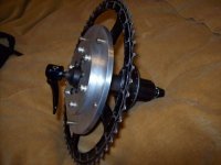
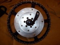
That chainring came from eBay for $1.00. The aluminum came from the scrap bin at a local machine shop. Yes, the sprocket's worn, but where else am I going to find a 56T chainring? Especially for that price?
I made a sprocket adapter to mount a 130mm chainring to a IS 6-bolt brake disc hub using a manual lathe and drill press. Lots of work to get everything centered.
I think it turned out pretty nice. Only problem is those socket head cap screws don't clear the frame by a few thousandths so I'll need to go pick up some button head screws to replace them tomorrow.


That chainring came from eBay for $1.00. The aluminum came from the scrap bin at a local machine shop. Yes, the sprocket's worn, but where else am I going to find a 56T chainring? Especially for that price?
I'm having a very hard time finding a suitable off-the-shelf clamp, so I designed my own.
These would require a fair amount of operations, but I've tried to optimize it as much as I can from what I know about the actual machining process (not much). I don't think it would require more than two repositions per side (4x for two clamps). I can post the STEP files in the repository if anyone would like. The center hole is 1-1/8".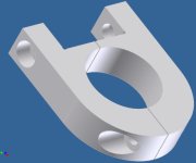
These would require a fair amount of operations, but I've tried to optimize it as much as I can from what I know about the actual machining process (not much). I don't think it would require more than two repositions per side (4x for two clamps). I can post the STEP files in the repository if anyone would like. The center hole is 1-1/8".

oofnik said:So, update time.
I made a sprocket adapter to mount a 130mm chainring to a IS 6-bolt brake disc hub using a manual lathe and drill press. Lots of work to get everything centered.
I think it turned out pretty nice. Only problem is those socket head cap screws don't clear the frame by a few thousandths so I'll need to go pick up some button head screws to replace them tomorrow.
View attachment 1
That chainring came from eBay for $1.00. The aluminum came from the scrap bin at a local machine shop. Yes, the sprocket's worn, but where else am I going to find a 56T chainring? Especially for that price?
nice...are they heavy?
Here's my pretend mounting solution.
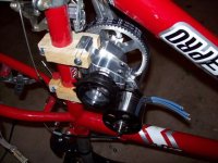
I have discovered that the chain line is just barely interfering with my rear V-brake mounts. I don't have a chain to check with so I used a power cord lying around. I just need a few millimeters more. So I may have to mount an idler to pull the chain in a little bit at the top. Which would be annoying because that's where the tension will be, and I will lose efficiency. Other option is to just go with a smaller sprocket. But it would have to be quite a few teeth smaller to clear. We'll just have to wait and see.
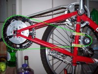
Another thing is the stop for the front shifter getting in the way of the clamps. But that's pretty easy - it's not a big deal to cut it off and put something in its place that sticks out a little further.
For those of you wondering, no, my frame did not magically become red this is my brother's bike which is identical to mine except for the color. I'm home for spring break and I just happen to have the identical frame back home to work with.

I have discovered that the chain line is just barely interfering with my rear V-brake mounts. I don't have a chain to check with so I used a power cord lying around. I just need a few millimeters more.

Another thing is the stop for the front shifter getting in the way of the clamps. But that's pretty easy - it's not a big deal to cut it off and put something in its place that sticks out a little further.
For those of you wondering, no, my frame did not magically become red
GGoodrum
1 MW
Looks good. Don't know if you saw these, but Matt was looking at have some made, but I'm not sure where it stands right now: http://www.endless-sphere.com/forums/viewtopic.php?f=28&t=7180&start=855#p137142 Anyway, looks like you are making good progress. 
-- Gary
-- Gary
Thanks, Gary.
Yes, I saw those clamps. I'm not sure what the status is on those either. They would be great, if only they existed in the real world. That's the thing about CAD/CAM, you can design all sorts of crazy awesome stuff and then you realize it is either extremely difficult, expensive, or both to actually make it.
Anyway I'm back in Chicago now. I tested the drive with the batteries and controller. The motor pulls 3.0 amps spinning at about 8400 RPM at full tilt, no load, mounted to the drive. I think that's acceptable. The drive has an added benefit of acting as a sort of heatsink for the motor, which is great. I'll play with the belt tensioning to try to get that no load current down. I also went down to an 80 tooth belt rather than the 81 tooth I got from Matt because I couldn't tension it quite all the way.
Yes, I saw those clamps. I'm not sure what the status is on those either. They would be great, if only they existed in the real world.
Anyway I'm back in Chicago now. I tested the drive with the batteries and controller. The motor pulls 3.0 amps spinning at about 8400 RPM at full tilt, no load, mounted to the drive. I think that's acceptable. The drive has an added benefit of acting as a sort of heatsink for the motor, which is great. I'll play with the belt tensioning to try to get that no load current down. I also went down to an 80 tooth belt rather than the 81 tooth I got from Matt because I couldn't tension it quite all the way.
MitchJi
10 MW
Hi,
Can you put the mounts a little lower on the seat-tube or make mounts that are offset to place the drive in a slightly different location? Is there more room to go lower if the drive is located further from the seat-tube?oofnik said:I have discovered that the chain line is just barely interfering with my rear V-brake mounts. I don't have a chain to check with so I used a power cord lying around. I just need a few millimeters more.So I may have to mount an idler to pull the chain in a little bit at the top.
Would you explain the problem a little more completely? I am tentatively planning on a 20t to 90t configuration. Do you think that will work?oofnik said:I also went down to an 80 tooth belt rather than the 81 tooth I got from Matt because I couldn't tension it quite all the way.
MitchJi said:Hi,
Can you put the mounts a little lower on the seat-tube or make mounts that are offset to place the drive in a slightly different location? Is there more room to go lower if the drive is located further from the seat-tube?
I may be able to do that. I don't have a way of making anything up here like I do at home.. no workshop, no drill press, no saws...
MitchJi said:Would you explain the problem a little more completely? I am tentatively planning on a 20t to 90t configuration. Do you think that will work?
If you mean 20t/90t pulleys, I'm not sure what the diameter of a 90t pulley would be. Oh, wait, yeah I do. It would be 5mm * 90 = 450mm circumference / pi = about 143mm diameter. I'll measure on my drive to see if there is enough room to mount it. You may have to go up in belt size however if you do that. I had to go down because with my 14t/70t setup, I couldn't mount my motor far out enough to keep tension on the belt. Timing belts aren't like chains or even V-belts - they need to be tensioned properly otherwise they wear out much faster and tend to be inefficient. Here's a technical article on the topic. They have a nice general rule:
That may give you a general idea of how much tension you want on your belt.Pretension prevents belt slack-side sagging and ensures proper tooth meshing. In most cases, timing belts perform best when the magnitude of slackside tension is about 10 to 30% that of the effective tension.
Hope this helps.
MitchJi
10 MW
Hi oofnik,
You could mount a similar clamp on the down-tube and use it to run a brace or braces to the seat-tube clamps to prevent them from moving.
MitchJi said:Hi,
Can you put the mounts a little lower on the seat-tube or make mounts that are offset to place the drive in a slightly different location? Is there more room to go lower if the drive is located further from the seat-tube?
oofnik said:I may be able to do that. I don't have a way of making anything up here like I do at home.. no workshop, no drill press, no saws...But I did consider doing that. It's not a bad idea. Only problem is that the distance between the drive and seat post is proportional to the moment (torque) about the clamps, and I would hate for those clamps to slip. But like I said, I only need a few mm, so it might be okay.
You could mount a similar clamp on the down-tube and use it to run a brace or braces to the seat-tube clamps to prevent them from moving.
Back to the electrical side of things, I tested my Headway pack with a resistive load: two 500W halogen bulbs in series. They draw an average of 160W, about 0.4C rate. Logging was done by an EagleTree V3 logger.
I charged and balanced the pack to 3.60 v / cell and let it stabilize for about 12 hours.
Cumulative capacity came out to 10111.5 mAH, 379 Wh.
The cells don't seem to be matched very well however. Some started tanking while others were still going strong. I disconnected as soon as I saw cell #6 dip below 2.0v. Others were still at 2.6v. :?
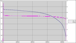
The final voltages after 30 mins of stabilizing were:
I will have to do several charge / discharge cycles to confirm that some cells are a bit weak. But as long as I'm monitoring the cell level discharge on the bike, everything should be okay.
I charged and balanced the pack to 3.60 v / cell and let it stabilize for about 12 hours.
Cumulative capacity came out to 10111.5 mAH, 379 Wh.
The cells don't seem to be matched very well however. Some started tanking while others were still going strong. I disconnected as soon as I saw cell #6 dip below 2.0v. Others were still at 2.6v. :?

The final voltages after 30 mins of stabilizing were:
Code:
1: 2.948           7: 2.894
2: 2.987           8: 3.095
3: 3.038           9: 3.004
4: 2.848          10: 3.090
5: 3.138          11: 3.062
6: 2.741 12: 3.020johnrobholmes
10 MW
In reference to your chain line and brake clearance, you could always grind a bit of brake away if needed. My campus cruiser rubs on the brakes a bit.
Thanks John. I'd rather not do something like that if I can avoid it. 
Currently it's looking less and less like I'll be able to make any sort of clamp. I just don't have the financial means nor the resources. So I'm currently looking at somehow mounting the drive to the two holes in my down tube where the water bottle mount used to sit, as this would give me a clear chain line. It would be much easier to do. I'd have to create a 3rd attachment though, but that won't really be much of a problem. I'll sketch it up sooner or later.
Currently it's looking less and less like I'll be able to make any sort of clamp. I just don't have the financial means nor the resources. So I'm currently looking at somehow mounting the drive to the two holes in my down tube where the water bottle mount used to sit, as this would give me a clear chain line. It would be much easier to do. I'd have to create a 3rd attachment though, but that won't really be much of a problem. I'll sketch it up sooner or later.
dontsendbubbamail
10 kW
- Joined
- May 28, 2008
- Messages
- 718
offnik,
I don't think the water bottle bosses are strong enough to handle the power of the motor. If that is a steel frame, the tubing thickness is about as thick as your thumb nail. Metal fatigue my get you. There is nothing wrong with using wood to make the mounts. The mounts you made look fine in terms of function. If you glue together some cabinet grade plywood from homedepot, assuming you are in the US, your current design for mounts will work. Don't discount wood. Machines have been made for centuries out of wood. Wood is more then strong enough to do the job. Wood is within your budget.
Bubba
MitchJi
10 MW
Hi offnik,
Maybe you can:
1. Get some aluminum bar stock, something like 1" x 1.5" or 1" x 2"
2. Cut the bars to length
3. Drill holes for bolting the bars together
4. Bolt the bars together with a spacer about 2mm thick between the bars
5. Use a drill press to drill a hole the size of the downtube at the junction of the two bars
6. Result one 1" thick clamp mount.
Removing the spacer and bolting the bars together will clamp the downtube with a lot of force. To attach the drive you can use the bolts to bolt angle stock to the clamps or make a notch (use a hack saw and/or grinder) in the end, similar to your current wood mounts.
If you have access to a drill press you probably need to purchase or rent the drill bit. If not I think you can probably afford to have two large holes drilled.
Something else you might be able to make work would be creatively using "band clamps". Something like the Wraplock products:
http://www.wraplockclamps.com/
Or the Band-it products:
http://www.band-it-idex.com/products/products_bandit.html
The Flair Leg BRACK-IT design provides a secure fit that locks each leg in
place on round poles or mast arms of almost every diameter.
Similar threads
- Replies
- 18
- Views
- 765
- Replies
- 76
- Views
- 4,217
- Replies
- 8
- Views
- 819

