stancecoke
100 kW
- Joined
- Aug 2, 2017
- Messages
- 1,811
kdog said:My mate has been through 3 40amp controllers all dying on Regen.
Did you use the stock firmware or our open source firmware?
regards
stancecoke
kdog said:My mate has been through 3 40amp controllers all dying on Regen.
")
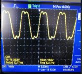
casainho said:Try to disable FOC and increase motor speed and current and then take the screen shoots and show to us.
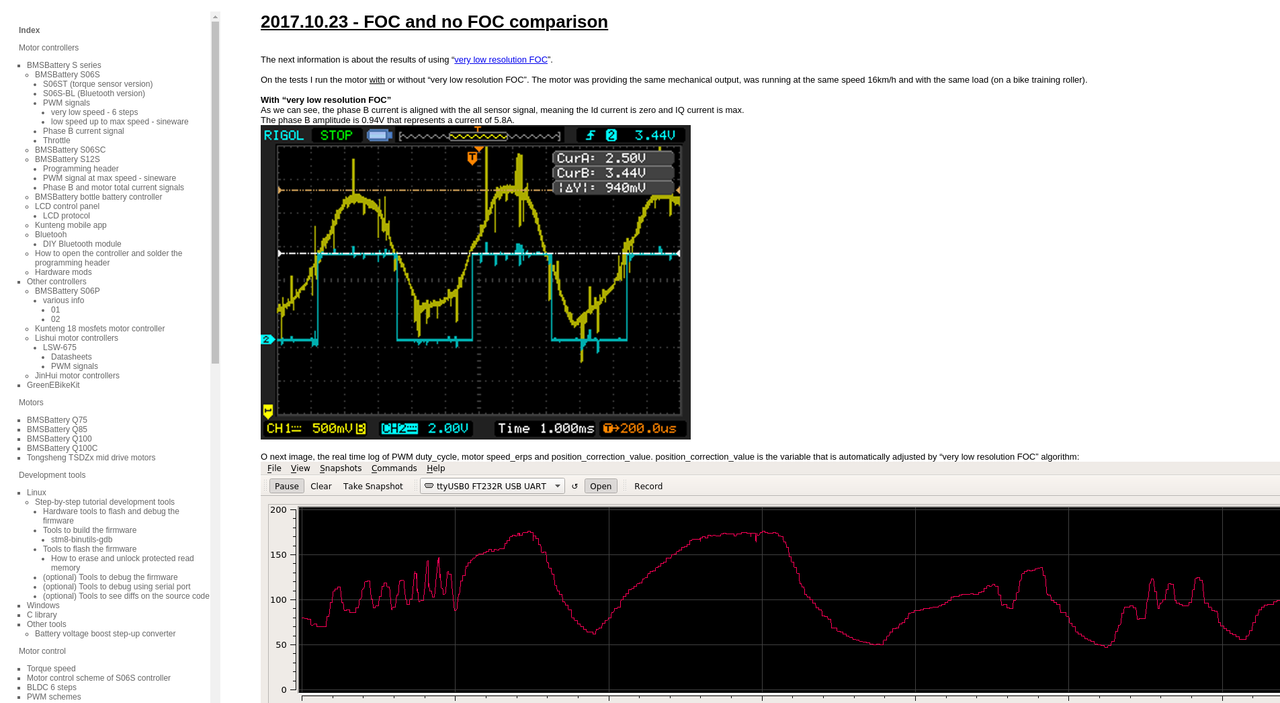
Go and read the notes I took when I developed and tested the FOC implementation: https://opensourceebikefirmware.bitbucket.io/development/Datasheets_and_application_notes--Endless-sphere.com_forum_messages--2017.10.23_-_FOC_and_no_FOC_comparison.htmlhaiyi911 said:casainho said:Try to disable FOC and increase motor speed and current and then take the screen shoots and show to us.
FOC was disable and the waveform was still asymmetrical.i tested other brands of controllers,there were all the same. maybe it is normal.
what is the angle interpolation used for?
#define DO_INTERPOLATION 1
#if DO_INTERPOLATION == 1
........
is the angle used to adjust the rotor position to keep ID=0?


That's ok, amplitude is proportional to current, no automatic upscaling is done.I only see a very slight sine wave
Can be adjusted in 5 steps just as power assist in the app.I can't see a setting for regen on/off
Cause nobody bothers to update the documentation. Voltage related logic has been replaced by overvoltage/undervoltage settings.Also, the Java documentation describes a 'cell number' option, but i can't find this?
Not going to happen. Don't want to invest time for SI refuseniks :wink: But you could think a moment about what I wrote about Gear ratio.Is there a way to change the app to display mph?
App Settings -> Motor temp?any suggestions on the best way to display that calculated temperature
duly notedXnyle said:Gear ratio is really only needed for determining the correct speed, motor will not turn differently if you change it, only the set speed limits work different then.
Not going to happen. Don't want to invest time for SI refuseniks :wink: But you could think a moment about what I wrote about Gear ratio.
App Settings -> Motor temp?
140, starts to stutter, practically stops at 70 and starts working again at 40
I'm not able to determine how to adjust these settings correctly
Is there any documentation on what the main App display is reading
davideserin said:I'm using the Sempu torque sensor and i have it working, but is it possible to use a throttle in addition to this?
With this option it just stays where it is until interpolation catches up again.
My first question: is this a real issue or desire for optimization? -- I ask this because I never felt anything that I think this can the source of an issue.buba said:I might as well mention another improvement that both I and my father wanted to have for a very long time. And you, thineight, have also mentioned this in your feedback.
This is the resolution of motor power for every ADC current step limited by the resolution of the ADC:
#define PHASE_CURRENT_OFFSET 128
#define PHASE_CURRENT_HYSTERESIS 0if (ui16_ADC_iq_current >> 2 > PHASE_CURRENT_OFFSET+PHASE_CURRENT_HYSTERESIS && ui8_position_correction_value < 143) {
ui8_position_correction_value++;
} else if (ui16_ADC_iq_current >> 2 < PHASE_CURRENT_OFFSET-PHASE_CURRENT_HYSTERESIS && ui8_position_correction_value > 111) {
ui8_position_correction_value--;
}