TSDZ2 mid drive with 860C, 850C or SW102 displays only -- Flexible OpenSource firmware (Casainho code only)

casainho said:
Dirkro said:
Sorry, in my opinion, by doing the tests, you add a lot of centerpieces from weight, steepness of road, speed, lost in the drive, lost of tires.
And that are the same conditions on both tests, right??

Both motor and pedals pull the bicycle wheel using the same chain. I guess we would have to discount some loss inside TSDZ2 gears and motor inefficiency. At least, in the end we could have an idea if we are around +- 25% of the real value, I think.

Dirkro said:
Î did mesurments with a analog torque wrench, diretly on the axle . they where good repeatable would guess 10% error, see below.

What does this formula show when you compare it with the existing calculation?
Please check by yourself here: calc_pedal_force_and_torque(void)
https://github.com/OpenSource-EBike-firmware/TSDZ2-Smart-EBike/blob/master/src/controller/ebike_app.c

I am not good in programming but I found following formular: 95.5 * (1/0.637) = 150 ...
Shouldn't it be 95.5*0.637=60.8 instead , (I rounded from 0.637 to 0.5 , *100 , so find good corelation then ?
 
Hi,
I'm going to buy a new TSDZ2 motor.

I will use this motor to remove parts to replace the parts that would fail in the engine that I have installed.

From what I read, a few months ago, the TSDZ2 motors that are now being manufactured have new gears.

Do you know of any seller in Aliexpress that has these new engines?

Do you also know if both 36V and 48V motors have the new gears?

I'm going to buy a 48V motor.

I think the controller is the same on the 36V and 48V motor? Do you confirm?

Thanks
 
stancecoke said:
Is the value of 0,52Nm per step based on the 32 steps between min and max value, or per unprocessed ADC value or per 1 of 1 ... 255?
Thanks. I need to review that code as there are parts that does not make sense now, like that mapping that were being used before we started to use the human power as a factor for motor power.

0.52NM per unprocessed ADC step. The comments are at least correct, I clear remember to make 0.33kgs of force on the digital fish scale for every ADC step.
 
casainho said:
0.52NM per unprocessed ADC step.
OK, but if you limit the allowed range to 32 ADC steps, the sensitivity of the sensor is very poor... The max value, you can dissolve is 32 * 0,52 = 16,64 Nm :confused:
If you put your 80 kg on the horizontal crank, you will get 800N * 0,17m (crank length) = 136 Nm Torque.

regards
stancecoke
 
Actually when I asked for the emtb mode I was interested above all because many users on the Italian forum say that it has an infinite extension ... which on the 48v I miss a lot. I don't know how it is done.
I think the tsdz2 is already very emtb. It is possible to dose the pedaling force going from low assistance values ​​to very high values.
I also think that such a mode in the absence of memory space on the LCD03 can simply be realized on the motor part without adjusting anything on the LCD03. For example, you could use level 1 for a fixed emtb. After all it works on vlcd5 which has no parameters to adjust.
 
stancecoke said:
casainho said:
0.52NM per unprocessed ADC step.
OK, but if you limit the allowed range to 32 ADC steps, the sensitivity of the sensor is very poor... The max value, you can dissolve is 32 * 0,52 = 16,64 Nm :confused:
If you put your 80 kg on the horizontal crank, you will get 800N * 0,17m (crank length) = 136 Nm Torque.
I just measured again.

My torque sensor shows on LCD3 the value 46 on rest. If I put 10kgs, it shows 59, so a delta of 13 --> 0.77 kgs for each ADC step (8 bits). This means in the full ADC range of 12 bits, it can measure as low as 0.19 kgs but that also probably would need low pass filtering to get that resolution and so a delay on the signal/delay on reaction of torque sensor signal.

With my full weight of 100 kgs on the pedal I got max value of 103, a delta of 57, so max read of 43.9 kgs.

@Buba, can we repair the code on the human power math for next stable version??
 
casainho said:
My torque sensor shows on LCD3 the value 46 on rest. If I put 10kgs, it shows 59, so a delta of 13 --> 0.77 kgs for each ADC step (8 bits). ... With my full weight of 100 kgs on the pedal I got max value of 103

So the output of the sensor is not linear. If you feed the three points 0 kg (0Nm), 10kg (17Nm) and 100kg (170Nm) to Excel and make a polinomal approximation you'll get this:


Perhaps you can do some more tests with e.g. 40kg and 60kg (let your child and your wife step on the pedal :wink: ) to get a better approximation.

regards
stancecoke
 
stancecoke said:
casainho said:
My torque sensor shows on LCD3 the value 46 on rest. If I put 10kgs, it shows 59, so a delta of 13 --> 0.77 kgs for each ADC step (8 bits). ... With my full weight of 100 kgs on the pedal I got max value of 103

So the output of the sensor is not linear. If you feed the three points 0 kg (0Nm), 10kg (17Nm) and 100kg (170Nm) to Excel and make a polinomal approximation you'll get this:

ADC-value vs torque.PNG

Perhaps you can do some more tests with e.g. 40kg and 60kg (let your child and your wife step on the pedal :wink: ) to get a better approximation.

regards
stancecoke
Sorry, I should made clear that is saturates to the 103 value. 103 does not mean 100 kgs!! It is hard for me alone to test how much kgs is the 103 max value but others users already measured and also verified it is linear.
 
casainho said:
Proposal for validating measured human power

As others did mention before, I wish we could validate our current measurement of human power as it seems an high value.

Human power is pedal cadence * force applied on the pedals. For pedal cadence, I think we can trust very well on our current measurement.

For force, I took measures using a digital fish scale with a good repeatability and resolution and the signal output is very linear.
I am afraid of incorrect measurements here because:
- we are not applying a constant force all over the 360 degrees of pedal rotation. On current code we consider a sinewave and the value is multiplied by an average coefficient of 0.637, still, final value seems high.
- the force measurement was done with pedal stopped, at 90 degrees from ground, however, with pedal rotation the signal may change, maybe it can have a positive increase with cadence increase, who knows??
- force signal change due to low pass filter on hardware, maybe with increase of cadence the signal increases??

I don't know about commercial bicycle pedal torque sensors but I guess they are very expensive. I don't want to buy and do such work for calibration and so I was thinking on alternatives and here is my idea:

1. by now, I think we trust well on the measurements done by TSDZ2 for battery(motor) current and battery voltage. I did calibrate with a good multimeter that measurements and other did validate after.
2. we could try to compare the battery power usage VERSUS human power usage to move a bicycle on the same external conditions: same ground inclination, same wind, same speed, same gear, etc.

Can anyone do some repetitive measurements like this:
1. pedal in medium inclination hill to achieve a constant wheel speed of like 10 kms/h (with TSDZ2 motor disabled) and take note of the measured human power on LCD3.
2. using walk assist and not pedaling, configure a PWM duty-cycle value in a way to achieve a constant wheel speed of 10 kms/h. Take note of the measured battery(motor) power on LCD3.
3. Repeat for different motor power values like: 100, 200, 400, 600 and 800 watts.

1. I tried that and LCD3 shows 0 (menu 9:5)
2. Walk assist worked in the beginning then motor make attack. It suddenly added more power and walk assist stop working.
I had motor power 400 W.
 
dameri said:
Can anyone do some repetitive measurements like this:
1. pedal in medium inclination hill to achieve a constant wheel speed of like 10 kms/h (with TSDZ2 motor disabled) and take note of the measured human power on LCD3.
2. using walk assist and not pedaling, configure a PWM duty-cycle value in a way to achieve a constant wheel speed of 10 kms/h. Take note of the measured battery(motor) power on LCD3.
3. Repeat for different motor power values like: 100, 200, 400, 600 and 800 watts.

1. I tried that and LCD3 shows 0 (menu 9:5)
2. Walk assist worked in the beginning then motor make attack. It suddenly added more power and walk assist stop working.
I had motor power 400 W.
[/quote]
1. Well, human power value shown on odometer field (I should mention that before)!!

2. Seems an issue with walk assist?
Maybe you can put max assist level possible and pedal just a little to make motor running at max power BUT limit max power to the values you desired like 100W, 200W, etc. That way the power will be limited to a fixed value and maybe you can also look at odometer to see your pedal power and discount that at the end or simple ignore very low values of it.

But please wait because we found that math is wrong on current firmware. After we correct it, would be nice to validate it that way you are testing.
 
casainho said:
stancecoke said:
casainho said:
0.52NM per unprocessed ADC step.
OK, but if you limit the allowed range to 32 ADC steps, the sensitivity of the sensor is very poor... The max value, you can dissolve is 32 * 0,52 = 16,64 Nm :confused:
If you put your 80 kg on the horizontal crank, you will get 800N * 0,17m (crank length) = 136 Nm Torque.
I just measured again.

My torque sensor shows on LCD3 the value 46 on rest. If I put 10kgs, it shows 59, so a delta of 13 --> 0.77 kgs for each ADC step (8 bits). This means in the full ADC range of 12 bits, it can measure as low as 0.19 kgs but that also probably would need low pass filtering to get that resolution and so a delay on the signal/delay on reaction of torque sensor signal.

With my full weight of 100 kgs on the pedal I got max value of 103, a delta of 57, so max read of 43.9 kgs.

@Buba, can we repair the code on the human power math for next stable version??

I have missed a lot of posts but will answer this one first.

I recommend to improve the human power calculation and measurement for the next stable release, version 0.20.0. But of course, release the stable 0.19.0 first, when the throttle has been confirmed to work.

I have already started some tests and asked the community about initial readings. Wanted to do a sensor and response model on the torque sensor we can use to more accurately measure human power. Was curious about the full range of operation, possible non-linearity, resolution and everything else relevant. Would then switch focus on the algorithm to see how it can be improved.

Have worked with sensors and noisy systems more often than not. Used different filtering algorithms and sometimes added hardware filtering. But hardware filtering is at the PCB design level and not applicable on the TSDZ2. But I am certain it can be improved with software.

The cadence sensor is assumed to be perfect for now. The torque sensor needs to be accurate enough, high enough resolution, measure fast enough and lastly have a good enough algorithm for the pedal strokes. I do not know to one hundred percent which of these parameters are lacking but I know from first principles that it is one or several mentioned parameters.

One important part is definitely the algorithm:

View attachment 1

 
casainho said:
dameri said:
Can anyone do some repetitive measurements like this:
1. pedal in medium inclination hill to achieve a constant wheel speed of like 10 kms/h (with TSDZ2 motor disabled) and take note of the measured human power on LCD3.
2. using walk assist and not pedaling, configure a PWM duty-cycle value in a way to achieve a constant wheel speed of 10 kms/h. Take note of the measured battery(motor) power on LCD3.
3. Repeat for different motor power values like: 100, 200, 400, 600 and 800 watts.

1. I tried that and LCD3 shows 0 (menu 9:5)
2. Walk assist worked in the beginning then motor make attack. It suddenly added more power and walk assist stop working.
I had motor power 400 W.
1. Well, human power value shown on odometer field (I should mention that before)!!

2. Seems an issue with walk assist?
Maybe you can put max assist level possible and pedal just a little to make motor running at max power BUT limit max power to the values you desired like 100W, 200W, etc. That way the power will be limited to a fixed value and maybe you can also look at odometer to see your pedal power and discount that at the end or simple ignore very low values of it.

But please wait because we found that math is wrong on current firmware. After we correct it, would be nice to validate it that way you are testing.
[/quote]
Ok, I'll wait and have little misunderstanding.
 
casainho said:
stancecoke said:
casainho said:
My torque sensor shows on LCD3 the value 46 on rest. If I put 10kgs, it shows 59, so a delta of 13 --> 0.77 kgs for each ADC step (8 bits). ... With my full weight of 100 kgs on the pedal I got max value of 103

So the output of the sensor is not linear. If you feed the three points 0 kg (0Nm), 10kg (17Nm) and 100kg (170Nm) to Excel and make a polinomal approximation you'll get this:


Perhaps you can do some more tests with e.g. 40kg and 60kg (let your child and your wife step on the pedal :wink: ) to get a better approximation.

regards
stancecoke
Sorry, I should made clear that is saturates to the 103 value. 103 does not mean 100 kgs!! It is hard for me alone to test how much kgs is the 103 max value but others users already measured and also verified it is linear.

Was so happy to see that graph. Because I have yet to test the upper range. Would be really interesting to study. But as the sensor was saturated and maxed out I quickly turned down the excitement. It seems to be a really impressive sensor nonetheless. Would never guessed that from such a cheap package.
 
In case you need to collect sensor data under defined load from the users (as buba started about a week ago), please try to sketch a procedure/guideline for a standard test (that can be repeatable) and we will collect our measurements. :wink:
 
casainho said:
Proposal for validating measured human power
1. by now, I think we trust well on the measurements done by TSDZ2 for battery(motor) current and battery voltage. I did calibrate with a good multimeter that measurements and other did validate after.
2. we could try to compare the battery power usage VERSUS human power usage to move a bicycle on the same external conditions: same ground inclination, same wind, same speed, same gear, etc.

Can anyone do some repetitive measurements like this:
1. pedal in medium inclination hill to achieve a constant wheel speed of like 10 kms/h (with TSDZ2 motor disabled) and take note of the measured human power on LCD3.
2. using walk assist and not pedaling, configure a PWM duty-cycle value in a way to achieve a constant wheel speed of 10 kms/h. Take note of the measured battery(motor) power on LCD3.
3. Repeat for different motor power values like: 100, 200, 400, 600 and 800 watts.

As you said, it is best to wait with further testing until we have improved the code.
But just wanted to mention that your proposal to validate the human power calculation is very good. For anyone wondering, this is a relative test and the absolute values do not matter. What matters is the relative value of human power and motor power during the same conditions.

* Replicate all runs at same start and end points
* Same inclination throughout the testing track
* Same speed, all tests
* Low and preferably no steering input
* Same user, all tests
* Same bike, all tests
* Needs to be tested at certain motor power levels!
* Needs to be tested at different user inputs but same human power: one test using high torque with low cadence, another using medium torque with medium cadence and lastly using low torque with high cadence
* Special development firmware that can maybe use constant PWM motor control at higher speeds during validation

Walk Assist only works at speeds below 8 km/h or around 5 mph. Above this speed it is disabled and if trying to enable Walk Assist over this speed Cruise will be activated, if it is enabled in the Configuration Menu.


thineight said:
In case you need to collect sensor data under defined load from the users (as buba started about a week ago), please try to sketch a procedure/guideline for a standard test (that can be repeatable) and we will collect our measurements. :wink:

Great support! When it is time to do some testing and validation a procedure/guideline will be made! The more data we get the better it usually gets!
 
buba said:
casainho said:
Proposal for validating measured human power
1. by now, I think we trust well on the measurements done by TSDZ2 for battery(motor) current and battery voltage. I did calibrate with a good multimeter that measurements and other did validate after.
2. we could try to compare the battery power usage VERSUS human power usage to move a bicycle on the same external conditions: same ground inclination, same wind, same speed, same gear, etc.

Can anyone do some repetitive measurements like this:
1. pedal in medium inclination hill to achieve a constant wheel speed of like 10 kms/h (with TSDZ2 motor disabled) and take note of the measured human power on LCD3.
2. using walk assist and not pedaling, configure a PWM duty-cycle value in a way to achieve a constant wheel speed of 10 kms/h. Take note of the measured battery(motor) power on LCD3.
3. Repeat for different motor power values like: 100, 200, 400, 600 and 800 watts.

As you said, it is best to wait with further testing until we have improved the code.
But just wanted to mention that your proposal to validate the human power calculation is very good. For anyone wondering, this is a relative test and the absolute values do not matter. What matters is the relative value of human power and motor power during the same conditions.

* Replicate all runs at same start and end points
* Same inclination throughout the testing track
* Same speed, all tests
* Low and preferably no steering input
* Same user, all tests
* Same bike, all tests
* Needs to be tested at certain motor power levels!
* Needs to be tested at different user inputs but same human power: one test using high torque with low cadence, another using medium torque with medium cadence and lastly using low torque with high cadence
* Special development firmware that can maybe use constant PWM motor control at higher speeds during validation

Walk Assist only works at speeds below 8 km/h or around 5 mph. Above this speed it is disabled and if trying to enable Walk Assist over this speed Cruise will be activated, if it is enabled in the Configuration Menu.


thineight said:
In case you need to collect sensor data under defined load from the users (as buba started about a week ago), please try to sketch a procedure/guideline for a standard test (that can be repeatable) and we will collect our measurements. :wink:

Great support! When it is time to do some testing and validation a procedure/guideline will be made! The more data we get the better it usually gets!

I didn't remember this. Maby that's why motor add more power when I tried to achieve 10 km/h and walk assist stop working.
 
dameri said:
buba said:
Walk Assist only works at speeds below 8 km/h or around 5 mph. Above this speed it is disabled and if trying to enable Walk Assist over this speed Cruise will be activated, if it is enabled in the Configuration Menu.

I didn't remember this. Maby that's why motor add more power when I tried to achieve 10 km/h and walk assist stop working.

Correct! :)


zappan said:
Hi Buba, in my bike I am using the code of Marcoq in the EMTB mode, I set the cadence at 100 rpm, the pedaling sensation in off-road is fantastic, there is no more reason to intervene on the levels of assistance in fact if you find in front of a steep climb you just need to push more on the pedals and get the maximum assistance, when you are on the plain the 80W max engine, in my off-road laps the battery consumption has increased a bit.
If I could have in the other bike with LCD3 I would be happy.

Thanks Zappan, interesting feedback! eMTB is something we definitely need to take a look at and add to the firmware in the future. For now there are a lot of things to do so can not say when this will be implemented but seems to be a great function!
 
buba said:
file.php

This diagram is correct for sensors, that only measure on one crank (like the Thun or the NTCE Bottom Bracket sensors).
Our sensor reads the torque from both cranks, so the graph is just sinusoidal.

In the KT-controller firmware we read a torque value at every PAS interrupt and average it over one crank revolution.
32 (=2^5) PAS Pulses per revolution

Code:
  	ui16_TORQUE_accumulated-=ui16_TORQUE_accumulated>>5; //Number of PAS Mags = 2^5 
	ui16_TORQUE_accumulated+=(uint8_t) map (ui8_adc_read_throttle (), ADC_THROTTLE_MIN_VALUE, ADC_THROTTLE_MAX_VALUE, 0, SETPOINT_MAX_VALUE);
	ui8_Torque = ui16_TORQUE_accumulated>>5;

I know, that casainho is no friend of interrupts :)

regards
stancecoke
 
stancecoke said:
buba said:

This diagram is correct for sensors, that only measure on one crank (like the Thun or the NTCE Bottom Bracket sensors).
Our sensor reads the torque from both cranks, so the graph is just sinusoidal.

In the KT-controller firmware we read a torque value at every PAS interrupt and average it over one crank revolution.
32 (=2^5) PAS Pulses per revolution

Code:
  	ui16_TORQUE_accumulated-=ui16_TORQUE_accumulated>>5; //Number of PAS Mags = 2^5 
	ui16_TORQUE_accumulated+=(uint8_t) map (ui8_adc_read_throttle (), ADC_THROTTLE_MIN_VALUE, ADC_THROTTLE_MAX_VALUE, 0, SETPOINT_MAX_VALUE);
	ui8_Torque = ui16_TORQUE_accumulated>>5;

I know, that casainho is no friend of interrupts :)

regards
stancecoke
We are reading at the same rate we need the signal to react to it: 100 ms. I guess this way is faster at least on low cadence.
Also TSDZ2 hardware seems to low pass filter very well the torque sensor signal, unlike on KT that can use any different torque sensor out there in the market.

So we just need to correct current constants on the code and the result should be good as almost for sure his output is linear. We are already counting with the sinosoidal signal.

Then we need to validate human power VERSUS motor power.
 
stancecoke said:
buba said:

This diagram is correct for sensors, that only measure on one crank (like the Thun or the NTCE Bottom Bracket sensors).
Our sensor reads the torque from both cranks, so the graph is just sinusoidal.

In the KT-controller firmware we read a torque value at every PAS interrupt and average it over one crank revolution.
32 (=2^5) PAS Pulses per revolution

Code:
  	ui16_TORQUE_accumulated-=ui16_TORQUE_accumulated>>5; //Number of PAS Mags = 2^5 
	ui16_TORQUE_accumulated+=(uint8_t) map (ui8_adc_read_throttle (), ADC_THROTTLE_MIN_VALUE, ADC_THROTTLE_MAX_VALUE, 0, SETPOINT_MAX_VALUE);
	ui8_Torque = ui16_TORQUE_accumulated>>5;

I know, that casainho is no friend of interrupts :)

regards
stancecoke

Fully aware, but wanted a simple graph showing the complexity of a single torque pulse and that the algorithm is a major part of the equation. Nice implementation!


casainho said:
We are reading at the same rate we need the signal to react to it: 100 ms. I guess this way is faster at least on low cadence.
Also TSDZ2 hardware seems to low pass filter very well the torque sensor signal, unlike on KT that can use any different torque sensor out there in the market.

So we just need to correct current constants on the code and the result should be good as almost for sure his output is linear. We are already counting with the sinosoidal signal.

Then we need to validate human power VERSUS motor power.

Here is one idea that I think will point us to a slightly better value for now.

Let us say we are very proficient in calculating the average torque applied during a single stroke. We are treating it just as one would treat a full wave rectified sinusoidal voltage over a load. We look at the maximum amplitude and multiply it with 0.637 and get the average voltage applied over the same load. This simplification is good enough for now so we will stick with it.

Now the idea.

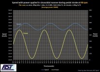
The cadence is also changing throughout the stroke. When pressure is applied to the pedals the speed of the bike is proportional to the crank cadence. And it decreases just before the next pedal stroke.


sinTorque.jpg


So, let us say that the cadence is our current in the analogy. Well, the full wave rectified sinusoidal current through a load also has an equivalent average current through the same load. This is actually the same formula used for the voltage: the maximum amplitude multiplied with 0.637.

If we take the equivalent average values of both waves we should get a better approximation of the average human power.

To conclude, average human power = 0.637 * torque * 0.637 * cadence ≈ 0.41 * torque * cadence

The analogy is lacking but is somewhat comparable in some aspects of the logic. Totally wrong approach if working with AC power though. But we are trying to approximate a coefficient for the calculation of mechanical power. If we are lucky this will be linear in the entire operating range. There will most certainly be a need for some sort of calibration determined through testing.
 
casainho said:
buba said:
I might as well mention another improvement that both I and my father wanted to have for a very long time. And you, thineight, have also mentioned this in your feedback.

This is the resolution of motor power for every ADC current step limited by the resolution of the ADC:

My first question: is this a real issue or desire for optimization? -- I ask this because I never felt anything that I think this can the source of an issue.

Sorry for the late reply!

The entire system is based on controlling the current, and it is therefore controlling the motor torque if in the normal operating mode. So the performance of the current control is dictated by how well the current is measured, and this is a function of the measuring frequency, the resolution and the accuracy of said measurements. This together with the user input is what determines the overall feeling and responsiveness of the system.

I just wanted to share my ambition to further improve the system with some possible benefits. It would especially be noticed during startups and other situations where finer resolution of the current control would be more noticeable.

* Smoother throughout the entire power range
* Every start would be more responsive with almost instant assist
* Smooth acceleration
* More continuous power levels
* Drive train would experience less stress
* Possible less consumption when not having to cycle between different power steps

Walk Assist is not controlled with current as the resolution is too coarse for the fine control that is needed. Instead, PWM control is utilized with almost 9 times the control resolution compared to the current control.


casainho said:
When I started this firmware, I had already developed a lot of it on the KT motor controllers OpenSource firmware. The TSDZ2 motor controller uses the same 8 bits 16MHz microcontroller STM8S105xx and so I just reused the most part of the code. The mainly big difference is the way the "low resolution FOC" algorithm is implemented because KT motor controllers has a specific part of the hardware to do it and on TSDZ2 it was to be done on a different way.

The STM8S105xx PWM channels that are in use have 16 bits resolution but I decided to use only 8 bits. The ADC channels have the resolution of 10 bits but I decided to use only 8 bits. The main advantages of using 8 bits are:

1. Faster processing speed
This microcontroller is very limited in terms of processing speed and to handle FOC we need to do it fast as possible. Also, we would like to increase the PWM frequency to make possible the motor to rotate faster with higher voltage and for that, we need more processing speed.

If not using the 8 bits resolution, the variables would be of 16 bits and the processing time would increase to a factor like x5 -- this would mean that probably FOC could not be implemented or would be worst resulting in the motor having less torque and the battery range would be lower.

I have noticed that a lot of work has been put down to optimize the execution time in the motor.c. Never stated to make it slower or make some compromises. Only as fast or faster. Together with improvements. I was not talking about a complete system redesign. The changes are limited to one single variable.

One approach would be to still keep the 8 bit value but convert it to ui8_battery_current_x6 or ui8_adc_battery_current. Then the operations and variable sizes of 8 bit would remain. Only difference is that we convert the 10 bit ADC value to 160 mA current steps during the ADC conversion. Not saying that is the best approach but am trying to convey that there are several ways of doing it and still maintaining speed and even simplifying code.


casainho said:
2. Low pass filter of analog signals
This motor has wires with high peak currents and PWM high frequency, meaning the electric signals should be noisy.

On the analog signals measured by the ADC, the first 2 bits of the 10 bits are being discarded and this results in a fast way that filters the noisy analog signals.

To discard two bits and therefore reduce the resolution with a factor of 4 is one way of filtering the values. This will remove noise that is between the 625 mA steps. But on the other hand you loose the resolution. Could be possible to filter the value in the same way the other measurements are filtered. But without having seen the type of noise and the amplitude I can not say much. Just that I have never used a sensor without some form of filtering. And more often than not it has been software filters.


casainho said:
3. Reducing programming memory usage
This microcontroller has very low memory size and so we need to save it if we want to implement advanced features like FOC.

The operations with 16 bits would increase to a factor like x4 the programming memory usage comparing to the 8 bits.

Am only talking about one variable and not the entire system. And can be made to 8 bit if going with the approach mentioned above.

-----------------------------

I take it as the community sees no real reason to go this path and there are other more important things to prioritize. That is totally fine! But I think it is good to have a discussion.
 
I ride a lot on the tsdz2 motor (more than 3000 km, using 36 volts and 48 volt motors with 36 and 52 volts batteries). I still use firmware 18.2 (I tried the newer firmware, but returned to 18.2). I use the motor a lot in difficult conditions: mountains, mud, subzero temperatures. I like almost everything in 18.2 except for a few moments. I would like off-road faster engine start (more than 10 amps per second. Maybe 15 or 20? I have iron gear and Japanese bearings everywhere (the Chinese all fail very quickly) and I need more power very quickly!) Another problem, the motor stops for a long time and spins for another 1-2 seconds after I stopped pedaling. Once this led to a chain bite due to dirt on the front gear and the motor managed to wind the chain in 1-2 seconds and pull out the rear derailleur with destruction. It would be great off-road to quickly stop the motor together with the speed of the pedals.
 
Here is an article on the new 2020 BoschCX motor

Just out of interest we have been talking about eMTB mode and I have been talking about reducing drag from the motor in case where you have a really low assist or max speed limit and you are trying to peddle faster than the motor.

Not really many take aways for this group but interesting that the max power assist has gone up from 300% to 340%. I guess this is easy for us to program when we setup each level even though there are technical reasons why we may never be able to achieve even 200%. This motor is now also lighter than the TSDZ2 which is pretty cool.

Enjoy
https://ebike-mtb.com/en/new-bosch-performance-line-cx-2020-motor-review/
 
buba said:
The cadence is also changing throughout the stroke.

This change is very very small, due to mass inertia, see the values on the y-axis in your plot.

buba said:
We look at the maximum amplitude and multiply it with 0.637

With this you will get most scatter. Over what period of time is the maximum measured? Refers the period to one crank revolution?
10 samples per second is much less than 32 samples per revolution at a "normal" cadence and you'll get aliasing effects with this small input rate.

buba said:
But we are trying to approximate a coefficient for the calculation of mechanical power.

You are right, the physics and the math is really simple. We just need to know cadence and torque in it's correct pyhsical units.

regards
stancecoke
 
Back
Top