Nine Continent 2809 rear hub build on '94 Stumpjumper

jag

10 kW
Joined
Feb 16, 2009
Messages
777
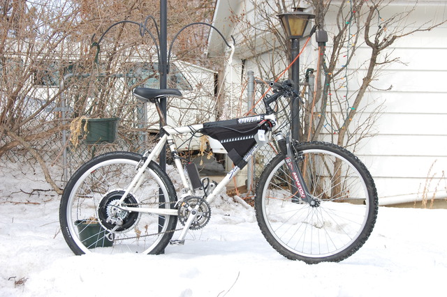
I built an eBike with the following parts:

Nine Continent 2809 rear hub
Crystalyte 30A 72V pedal first
Cycleanalyst
NiCd 8Ah, 1 or 2x 36V
All parts from ebikes.ca
built on a '94 Spezialized Stumpjumper hardtail MTB
Weight 32Kg w. 2x36V battery packs.

Some notes:
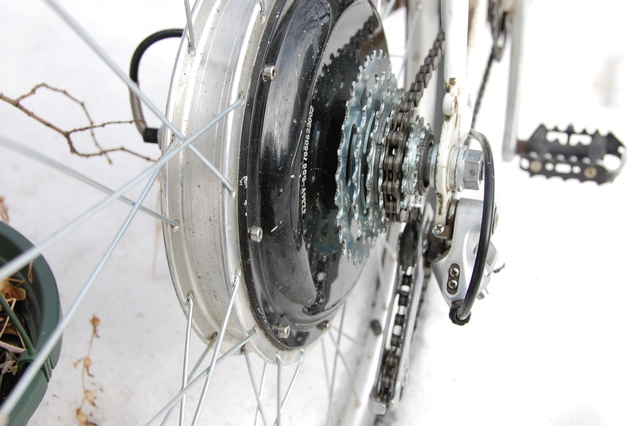
I needed a small spacer on the axle (freewheel side) to fit a 7sp freewheel.
Increased dropout spacing from 135mm to 145mm using 2x4 method on SheldonBrown.org
Rebuilt wheel with spokes threaded inside-out on freewheel side to allow more dishing, see image.
Achieved centered rim by dishing 2/3 towards freewheel side.
Performance (on the flats): 25km/h @180-200W at 36V, 45-50km/h @800-1000W at 72V
Peak power: 1.8kW going uphill.

Batteries in frame triangle and rear hub motor gives good weight balance. It will take me a while to get used to the handling with the extra weight. Otherwise it rides well, and feels stable at speed. Frame is very nice. Light CrMo, good geometyry to fit batteries, and brazeons for panniers and fenders. Fork is a bit floppy. Probably worn. It is however not so easy to find a good suspension fork for a 1" steerer tube nowdays.

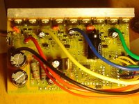
Sometime later I will clean up the cabling, and make a custom bag fitting both 36V batteries and the controller, then transfer rack, panniers and fenders from my current commuter bike. For now I strapped 2nd battery (not shown in image) to top tube behind first.

Martin (In Edmonton, AB)

dsc_0023_sm.JPG

dsc_0024_sm.JPG
 
how much spacer, how wide is your fork and how hard was it to spread that far?

i have a rockhopper, about to do an identical build with a 9C rear and am gonna get the 7 speed freewheel from justin too. what is count on your big front crank?

i have a total of 9.5Ah 48V nicad, in 2 packs from justin originally. gonna adjust the 9FET infineon controller from 36V to 48V.

so sorry about the snow. we finally got over 70.
 
> how much spacer,
I put in a 4mm spacer. 1-2mm would have been enough. I heard some get away w/o any spacer. It might be that the axle is pressed in a little different due to manufacturing tolerances, or maybe different 7sp frewheels end up seating at slightly different distance.

> how wide is your fork and how hard was it to spread that far?
Original was a standard 135mm. Axle is also 135mm, but I spread to 145mm to account for: 2x NineContinent torque washer (2x3mm) and my 4mm spacer.

Frame was stiffer to spread than I had thought. Used a 4ft piece of 2x4 as lever and had to jump on it for about 1/2h before I got 6mm increase on freewheel side and 4mm on the other. (Intentionally asymetrical to reduce wheel dishing)

> what is count on your big front crank?
48 tooth. Seems comfortable up to the 40's (km/h), but a bit low for 50.

> so sorry about the snow. we finally got over 70.
Winter bike riding is not so bad. Done it all my life. Not as pleasant as warm weather cycling though. Maybe I should become an eBike based "snowbird" and migrate south seasonally... (provided there are charging spots along the way)

Martin
 
neat idea, spread the frame asymmetrically to reduce the dishing, i am gonna do that too, how did you hold the frame? that is the story, how could you measure how far you bent to each side, by bending one side first and then the other?
 
> neat idea, spread the frame asymmetrically to reduce the dishing, i am gonna do that too, how did you hold the frame?
See pics here:
http://www.sheldonbrown.com/frame-spacing.html

> how could you measure how far you bent to each side, by bending one side first and then the other?
Yes, bend one side first, then the other. Measure progress with a steel scale between dropouts.

Martin
 
Second week experiences:
Comfortable cruising speed is in the 40km/h's.
I seem to be getting about 30km range on the 72V, 8Ah NiCd.

Spokes started making a rubbing noise. I tightened them again
a second time now. Seems like Sheldon Brown has a good point
that spokes have to stretch and settle before a wheel is finalized.
After trueing, first tightening was 1 turn/spoke, and today second
tightening was 3/4 turn. Now wheel is nice and stiff again.

Martin
 
bravo, 72V, that will be 84V hot off the charger.

i am working on my 9 FET infineon controller to run up there. but will build it first to run at 56V max from my 48V nicad.

i actually think you can run your 2 packs in series now with the infineon, but it has 63V input caps and i think they will burn up and take the
FETs with them. the FETs are 75V75A but i think with larger input caps they will not get too much spiking and maybe survive the initial pack voltage. it will sag almost immediately into the 70V range so it should work with the stock FETs, but i think it will need 100V1000uF caps (2) on the input, and another one on the S/D busses.

the problem is finding space inside the controller for the input caps, and i have decided to make space by moving the power resistors from the top of the board and placing them underneath with an additional power resistor to get the proper voltage drop to the input of the voltage regulator, and then use the remaining 36mm x 40 mm space for the two new 100V1000uF caps.

i found these on digikey, but may use some others which are 18mm diam by 35mm long. the current input caps are 12mm diam by 20mm high. 36 mm from the small caps on the 5V buss over to the end plate, and 40mm from the outside to where the power cables run across next to the output FETs.
 

Attachments

  • IMG_0001.JPG
    IMG_0001.JPG
    56.5 KB · Views: 6,185
  • DSC00218.JPG
    DSC00218.JPG
    73.4 KB · Views: 5,886
If you cannot a find small enough 1000uF 100V capacitors you could
put two 500uF 100V in parallel.

I'm really not the expert to ask on component selection though.
I was wondering about the details about capacitor selection the other day myself.
The capacitors may serve several purposes:
* suppress any voltage spikes (preventing damage to FET and other circuitry)
* Even the load on the batteries. At partial duty cycle the switched controller will
draw full load for short durations. A capacitor can even the draw from the battery,
and result in an apparent lower internal resistance.
* And maybe multiple other purposes.

I was also surprised to see rather standard electronics electolytic capacitors
for this applicastions instead of something fancier, more suited to the
high currents and high frequency. (Just look at the screw connections
and packaging on some of the industrial duty capacitors...)

Martin
 
if i run the controller at 88 volt off lithium, that is so far above the 63V of the normal caps, it would blow them up immediately, so i figured they have to go. but if i can absorb the voltage spikes before they get to the FETs, i think the sag will be low enuff to keep the voltage across the FETs from staying so high they break.

so i could push the controller to perform at 72V while still using the original FETs. which is why i want to use 1000uF caps, and not 470uF.

so i see it as the cheapest way to upgrade to 72V. keywin sells these controller for $22, so you could add $3.10 in caps for the three 100V1000uF, which is 18mm x 40mm, or $6 for the panasonics NHG which are identical to the rubycon YK that they use in the 18FET controller. those are 35.5mmlong and 18mm so they will fit with an extra 5mm space, but the ripple current is lower than these cheap ones is actually better (1380 vs 985).

i will actually try to build it first to 72V by adding another power resistor in series with R1A, and put both of them and the power resistor across the Vin-Vout which is R6 i think, underneath by desoldering and installing underneath.

let the heat from the power resistor warm up the bottom metal plate of the controller, without touching because i am also gonna put a cermet for the adjustable LVC over on the underside right under the output shunts and it will act like a spacer under the pcb.

there is a free space next to the ground return on the pcb where i can solder the cermet to ground and the other end to bypass R12 with a wire running out to the top of the board. then the LVC can be adjusted later, with more experience of how it performs as i change the LVC.

anyway the cermet in digikey is 5mm thick so the bottom of the pcb will be held out that far, and i can put a plastic square farther back to push it off the bottom, and then the power resistors would radiate a lotta their heat to the metal of the bottom, and the heated air would be underneath the board, away from the voltage regulator. cheap and dirty. but effective.

i am eventually maybe gonna add on top, in that space adjacent the big caps, a transistor mod next to the voltage regulator (similar to what knuckles and phil did). that would be a cheap upgrade too by allowing the entire controller being upgraded above 100V with the irfb4110s from bob.

so maybe this little box could be upgraded so it has 2/3 of the driver FETs as the 18FET version so essentially 67% of the power, just easier to hack, and cheapcheapcheap. with its attendant quality control somewhat mitigated.

desoldering and resoldering the FETs and adding the mica to the heatsink is all above my technical level now. but then it would be equivalent to your C'lyte controller, and run at 72V without problems. but the 4110 are only $2.50 from bob so i can rebuild 3 controllers for $10.41 in caps (10 pack), 60 cents for the cermet multiturn pots (if i buy the 50 pack for $10 from the china vendor), and $21.50 for the FETs from bob. $32.51 or $10.84 per controller. add another $1 for the smaller panasonic caps. add maybe $2 for parts to do the transistor mod.

but now i think the best mod that way for multi voltage operation, is to go with a cheap dcdc converter for the controller current. and use the dcdc converter to power lights and accessories like a sound strobe for an alarm and horn. something that has a big wallop of noise. like a neutron bomb for cars.
 
Back
Top