Power PCB for Lebowski Controller to be combined with Bobc's processor board

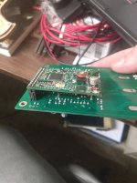
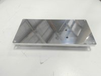
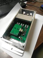
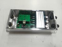
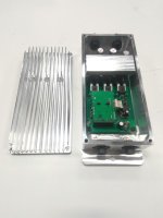
And we're done, minus our R1 and R2 that I had to order some more resistors for. I elected to go ahead and leave the board on bottom for testing, then will move it to the top later when everything is proven. I need to source some connectors for the brain board external inputs, as well. Any thoughts? I don't want to solder them directly. JST?

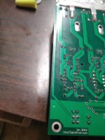
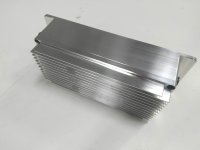
Power stage pics are before soldering the brain header back on.
 

Attachments

  • IMG_20190426_154100.jpg
    IMG_20190426_154100.jpg
    85.5 KB · Views: 2,758
Alright brain trust, tried powering up for the first time and it was a miserable failure. Tried powering up the brain board separately and saw the faintest flicker from an LED, then nothing. I can't see anything obvious as to why there'd be an issue. Anyone want to take a shot at diagnosing the package? Happy to pay for your time.
 
coleasterling said:
Alright brain trust, tried powering up for the first time and it was a miserable failure. Tried powering up the brain board separately and saw the faintest flicker from an LED, then nothing. I can't see anything obvious as to why there'd be an issue. Anyone want to take a shot at diagnosing the package? Happy to pay for your time.

The first thing you need to do is verify you have +5V going to the brain and +15V going to the fet drivers.
 
kiwifiat said:
The first thing you need to do is verify you have +5V going to the brain and +15V going to the fet drivers.

No +15V or +5V, both on the power board and powering pin 14 (Edit: This was also a mistake?) with 35V and using pin 21, 17, or 9 as ground.

EDIT: Bad, bad, bad news bears. I've apparently killed the microcontroller. I gave it 5V power through the hall connection as seen in BobC's original thread and saw smoking on the dspic. Don't really have a clue what I did, which is probably the problem.

At this point, I'm happy to send the assembly away for someone else to fix and happy to pay for it. Whereswally606, interested?
 
have you got the orientation of the board correct??

note that when you flip the board over, assuming your layout shows Pin 1 as Top-Right on the Brain board (the square pin), your Brain Board pin 1 actually goes to this pin shown... so note that there is a PIN translation, and you need to be careful how the board is oriented. I'd need to see the PCB layout and the schematic to be sure.
pic.jpg

**EDIT**
I just read back through the thread, looks like you have it the same as others, that's probably not the problem though, I just get worried when I see people mounting boards upside-down underneath other boards, and then referencing pin numbers...

All good.
Andy
 
coleasterling said:
EDIT: Bad, bad, bad news bears. I've apparently killed the microcontroller. I gave it 5V power through the hall connection as seen in BobC's original thread and saw smoking on the dspic. Don't really have a clue what I did, which is probably the problem.

At this point, I'm happy to send the assembly away for someone else to fix and happy to pay for it. Whereswally606, interested?

That is odd, powering the 5V rail directly would not under normal circumstances cause the magic smoke to escape. If Whereswally606 can't help you can send to me, replacing the DSPIC is not a big deal but I suspect there will be some other debugging required.
 
kiwifiat said:
That is odd, powering the 5V rail directly would not under normal circumstances cause the magic smoke to escape. If Whereswally606 can't help you can send to me, replacing the DSPIC is not a big deal but I suspect there will be some other debugging required.

Thanks sir! I'll keep that in mind. I didn't think there would be an issue with it either, though I suppose it could have been damaged from the first test?
 
Due to family and other commitments im not able to help. I also dont have the knowledge/tools that bobc or lebowski had/has to debug or fix and currently im not setup for producing any replacements anytime soon. Kiwifiat thats a good offer and if you need spare components i may be able to send you them if i have them. I do want to see these controllers working.
 
No trouble, thank you for all you've done already!

I've contacted Lebowski, but haven't heard back, yet. Kiwi, if you want a shot at it, I'm happy to send your way. I think we'll have to get Lebowski involved somehow, since it'll need a new dspic, but no need to have him do it all.
 
coleasterling said:
No trouble, thank you for all you've done already!

I've contacted Lebowski, but haven't heard back, yet. Kiwi, if you want a shot at it, I'm happy to send your way. I think we'll have to get Lebowski involved somehow, since it'll need a new dspic, but no need to have him do it all.

I'll pm you my address, I have a couple of dspic's I can use one of those now. When you order a replacement get Lebowski to send it to me directly.
 
Hey guys. This has been playing on my mind a while. I dont think the circuit for the 80v to 15v is anywhere near as robust as required. With that said i bought an 80v to 15v circuit on alibaba to off load this job from the brain board.

I will reiterate i have very limited time to help but i will send you the link to the part i bought which i havent tested yet.

It is kind of leveraging mass production abit as i think the parts cost and time to make this board is considerable. Plus if the 80v dc goes pop you can more easily solder in a new one. I would get a few spares on hand.

Wholesale Product Snapshot Product name is 12W DC 80V-24V to 15V HV DC-DC Buck Step-Down Converter Voltage Regulator Board Power Supply Module
https://www.aliexpress.com/snapshot/0.html?spm=a2g0s.9042647.6.2.51d84c4dD53RiF&orderId=101496767424610&productId=32822090487

Also i may have some broke brain boards which i can send you kiwi if you can help Cole as i am have zero time to help myself. I am grateful to both of you for pushing ahead with the project.
 
Thank you for the link, but it seems to be dead.

Thanks for the offer on the brain boards! If we do end up needing one, just shoot me an invoice on paypal and I'll take care of it immediately.
 
whereswally606 said:
Hey guys. This has been playing on my mind a while. I dont think the circuit for the 80v to 15v is anywhere near as robust as required. With that said i bought an 80v to 15v circuit on alibaba to off load this job from the brain board.

I will reiterate i have very limited time to help but i will send you the link to the part i bought which i havent tested yet.

It is kind of leveraging mass production abit as i think the parts cost and time to make this board is considerable. Plus if the 80v dc goes pop you can more easily solder in a new one. I would get a few spares on hand.

Wholesale Product Snapshot Product name is 12W DC 80V-24V to 15V HV DC-DC Buck Step-Down Converter Voltage Regulator Board Power Supply Module
https://www.aliexpress.com/snapshot/0.html?spm=a2g0s.9042647.6.2.51d84c4dD53RiF&orderId=101496767424610&productId=32822090487

Also i may have some broke brain boards which i can send you kiwi if you can help Cole as i am have zero time to help myself. I am grateful to both of you for pushing ahead with the project.

Thanks for the offer, the boards should turn up next week and I will let you know then. I am also keen to see lots of these controllers running after seeing what great results zombiess and Arlo1 got and every one built helps support Lebowski.
 
Animalector said:
I'm doing that as well with my design (but I'm getting a part from Digi-Key) one day I'll get around to finishing it and actually building one up

Andy

Your version looks very professional, it would be nice to see a lot of them in use.
 
Thanks to Whereswally606 who sent me two blown boards from which I was able to scavenge almost enough parts to repair Coles blown BobC board.

A big heads up to anyone using BobC's board and following the build instructions, there is a typographical error where it is suggested that the board can be tested by applying battery voltage to the "bat" pin which is pin 14 on the board. If you do that you will fry the DSPIC and depending on the voltage applied most of the other silicon on the board. The instructions should read BPOW. The BAT pin is in fact the battery voltage feedback pin and is connected directly to the DSPIC.

Attached a short video showing Coleasterling's repaired board in action on a small RC motor and a Heinzmann PMS120W.

https://youtu.be/Hy8pevKWNp4

[youtube]Hy8pevKWNp4[/youtube]
 
kiwifiat said:
A big heads up to anyone using BobC's board and following the build instructions, there is a typographical error where it is suggested that the board can be tested by applying battery voltage to the "bat" pin which is pin 14 on the board. If you do that you will fry the DSPIC and depending on the voltage applied most of the other silicon on the board. The instructions should read BPOW. The BAT pin is in fact the battery voltage feedback pin and is connected directly to the DSPIC.

Yeah...
If anyone has an interest in Power PCB + BobC's board (with exact fallout described above) and with custom CNC-milled aluminum enclosure, please let me know. I have abandoned this project (in favor over nucular).
 
[youtube]Hy8pevKWNp4[/youtube]

hey Kiwi to embed yt clips just put the code i.e. Hy8pevKWNp4 at the end in the tag. Sad that this is no longer really supported but at least you see the image of the video
 
Lebowski said:
On the bottom of the PCB, on the left (so with the temperature sensor on the right), there is a line going from the battery voltage to the two resistors that feed the battery voltage to the processor board. I would put a switch in this line...

I'm torn on this one. What I really want is 3-step process for turning on, then arming the system. Initial turn on would precharge and close the contactor. That's easy. Second, I want to turn power to the controller on separately from the high voltage. This doesn't have to be done by the user. Maybe through the precharge relay? Third, I want a method to enable throttle with a big, nasty, bright or easily audible signal that the bike is armed and ready to go. There have been too many times already where people unfamiliar with electric bikes will play with the throttle and it isn't immediately apparent what state the system is in.

On the second one, you're talking about the far left line in the picture, correct? Just cut that and wire a switch in line? I have a voltage-rated switch that will do it just fine (not even close to $0.5).

Do you have any ideas on the third? I'm guessing it isn't a good idea just to interrupt the +5V to the hall throttle, no?
 

Attachments

  • IMG_20190731_072716.jpg
    IMG_20190731_072716.jpg
    153.8 KB · Views: 2,082
And a little preview of what's to come, finished this guy tonight:
 

Attachments

  • IMG_20190801_004304.jpg
    IMG_20190801_004304.jpg
    109.2 KB · Views: 2,056
  • IMG_20190801_004328.jpg
    IMG_20190801_004328.jpg
    117.2 KB · Views: 2,056
  • IMG_20190801_004524.jpg
    IMG_20190801_004524.jpg
    104.9 KB · Views: 2,056
  • IMG_20190801_004341.jpg
    IMG_20190801_004341.jpg
    121.8 KB · Views: 2,056
I originally planned to 3d print a lower case out of petg, but had a terrible print and I had some down time today when some parts for the rest of my mini bike didn't show up. I ended up machining the lower case and making some significant changes to end up with the board on top as I originally planned. I'm pretty happy with how it has turned out so far.
 

Attachments

  • IMG_20190801_163016.jpg
    IMG_20190801_163016.jpg
    265.8 KB · Views: 2,024
  • IMG_20190801_211628.jpg
    IMG_20190801_211628.jpg
    88.6 KB · Views: 2,024
  • IMG_20190801_210644.jpg
    IMG_20190801_210644.jpg
    164.4 KB · Views: 2,024
  • IMG_20190801_205849.jpg
    IMG_20190801_205849.jpg
    127.4 KB · Views: 2,024
  • IMG_20190801_205505.jpg
    IMG_20190801_205505.jpg
    105.1 KB · Views: 2,024
  • IMG_20190801_170347.jpg
    IMG_20190801_170347.jpg
    272.5 KB · Views: 2,024
  • IMG_20190801_211729.jpg
    IMG_20190801_211729.jpg
    93.8 KB · Views: 2,024
  • IMG_20190801_212143.jpg
    IMG_20190801_212143.jpg
    120.6 KB · Views: 2,024
  • IMG_20190801_212411.jpg
    IMG_20190801_212411.jpg
    128.1 KB · Views: 2,024
  • IMG_20190801_213800.jpg
    IMG_20190801_213800.jpg
    163.6 KB · Views: 2,024
Wow! Superb work on that case.
Think about the hours of work drawing, programming, and machining...
You're not going to get this beauty splashed with mud under the bike, aren't you? :lol:
 
Altair said:
Wow! Superb work on that case.
Think about the hours of work drawing, programming, and machining...
You're not going to get this beauty splashed with mud under the bike, aren't you? :lol:

Thanks! I do this stuff literally every day for my business, so it didn't take just too long. Total time with heatsink and lower enclosure for design, machining, and finishing was around 8 hours. Changing the board to the top and wiring everything, that was awhile. Probably about the same amount of time. I'm slow at that stuff.
 
Looks amazing cole. Do a video please once its mobile. :D
 
Back
Top