bruwie
1 mW
Look herethineight said:Where is the 0.20 wiki? I'm curious to have a look at it in the meantime... :wink:
Thanks
https://github.com/OpenSource-EBike-firmware/TSDZ2_wiki/wiki/0.20.0
Look herethineight said:Where is the 0.20 wiki? I'm curious to have a look at it in the meantime... :wink:
Thanks
Target Chip eraseperryscope said:That's odd. But glad it's working for you. Would you mind uploading a screenshot of the stm32 st-link main window. Does it look like the bytes are correct for the .bin file. Also did you erase from stm32 st-link or was the screen already flashed?


bruwie said:Target Chip eraseperryscope said:That's odd. But glad it's working for you. Would you mind uploading a screenshot of the stm32 st-link main window. Does it look like the bytes are correct for the .bin file. Also did you erase from stm32 st-link or was the screen already flashed?

fi7ippo said:Hi Buba I saw the 0.20.0 wiki, wonderful, You have make a epic job
Is it safe to compile and test?
fi7ippo said:I read a bit the code and maybe I don't understand well, but on
src/controller/adc.c says
64 // read ADC torque sensor value
65 uint16_t ui16_temp = UI16_ADC_10_BIT_TORQUE_SENSOR;
66
67 // filter the ADC torque sensor value and set to offset variable
68 ui16_filter(&ui16_temp, &ui16_adc_pedal_torque_offset, 9);
what is ui16_temp ?
fi7ippo said:I've not yet understand what is the difference in the new 4 type motor logic, (torque - pas - cadence - emtb) but I'll try when a beta will available
fi7ippo said:On the new wiki there is a new parameter scale on menu (9 Motor Controller Setup)
2 Motor acceleration 70%
What scale have the new parameter 2 Motor acceleration? Maybe 100% for 10A/s rump up or what?
fi7ippo said:Option 3 Pedal torque conversion factor - and 4 Weight on pedal is perfect, wow, wonderful work :thumb: :thumb:
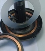
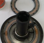
fi7ippo said:I had some time to swap the torque sensor with a brand new untouched new one, and I can say that the new sensor have a lower range, rest 31-32 maximum about 74 and lower capacity (about 40kg) but I'll post a complete data in a few days!
Among other things I forgot to install the white Teflon thickness before the torque sensor, and I would not damage the sensor windings, so I will have to disassemble it again.
I have also noticed that without this thickness inside it all seems smoother than before when a rubbing noise was heard, I think I will try it without thickness for about fifty km.
Thank You Buba, have a nice day!
buba said:casainho said:That happens to me just like you describe, in v0.19.0.hefest said:After some time with new version of firmware, it looks like the "no power" issue is still there, but not as pronounced as before.
I think I figured out the way to reproduce it, although not every time.
On red light, with brakes with sensors on and sitting on the bike with feet on the pedals. When I start, there is no power for few seconds and display is slowing 0 watts. With older version of firmware this was more frequent and it was taking more time.
Are you guys using Startup Boost? Does it happen with it off?
Have no power issue in the 0.20.0 development but am not using Startup Boost either. Did experience some slow starts in the 0.19.0 though.
hefest said:I'm using startup boost yes. Will try with boost off once the weather allows.
casainho said:I was not using Startup Boost when I got that issue.
thineight said:fi7ippo said:Hi Buba I saw the 0.20.0 wiki, wonderful, You have make a epic job
Where is the 0.20 wiki? I'm curious to have a look at it in the meantime... :wink:
Thanks
AZUR said:Hi,
Can I buy the display at PSWPOWER, on Aliexpress?
Full colorful LCD P850C display.
At this link:
https://www.aliexpress.com/item/32664961322.html?spm=a2g0o.cart.0.0.7bf33c00QCUMa1
Many thanks,
Azur
Please take a picture of the microcontroller to make sure it is another version from the ones I have, see here a picture showingperryscope said:bruwie said:Target Chip eraseperryscope said:That's odd. But glad it's working for you. Would you mind uploading a screenshot of the stm32 st-link main window. Does it look like the bytes are correct for the .bin file. Also did you erase from stm32 st-link or was the screen already flashed?
Yes those are the steps I followed but it looks like my 850C is only 256K bytes? I wonder if that's the difference?
850-C-256k.PNG
Please take a picture of the microcontroller to make sure it is another version from the ones I have, see here a picture showing:perryscope said:bruwie said:Target Chip eraseperryscope said:That's odd. But glad it's working for you. Would you mind uploading a screenshot of the stm32 st-link main window. Does it look like the bytes are correct for the .bin file. Also did you erase from stm32 st-link or was the screen already flashed?
Yes those are the steps I followed but it looks like my 850C is only 256K bytes? I wonder if that's the difference?
850-C-256k.PNG
I am bending the connectors wires so I can solder on the pads. Would be nice if you guys can share pictures so I can update the wiki.sabergo said:I've downloaded the proper software and files and exposed the programming pads. The pads are quite a bit narrower than the LCD-3 connectors. Are you soldering pins to the pads or just bending programming pins from the st link five wire into a narrower width? I was thinking to cut the corner out and hotglue pins to pads -- so that future flashing can be done without opening the case.
Wonderful work and thanks to all of the programmers.
dameri said:AZUR said:Hi,
Can I buy the display at PSWPOWER, on Aliexpress?
Full colorful LCD P850C display.
At this link:
https://www.aliexpress.com/item/32664961322.html?spm=a2g0o.cart.0.0.7bf33c00QCUMa1
Many thanks,
Azur
PSWPOWER: http://www.pswpower.com/ven.php?cargo.2016-5e-2eaj
Yes it does, I am running 2 of them on different bicycles with 14S3P battery packs.fi7ippo said:dameri said:AZUR said:Hi,
Can I buy the display at PSWPOWER, on Aliexpress?
Full colorful LCD P850C display.
At this link:
https://www.aliexpress.com/item/32664961322.html?spm=a2g0o.cart.0.0.7bf33c00QCUMa1
Many thanks,
Azur
PSWPOWER: http://www.pswpower.com/ven.php?cargo.2016-5e-2eaj
Hi guys does the P850C works with 14s 58,8v battery?
Thank You
casainho said:Please take a picture of the microcontroller to make sure it is another version from the ones I have, see here a picture showing:perryscope said:bruwie said:Target Chip eraseperryscope said:That's odd. But glad it's working for you. Would you mind uploading a screenshot of the stm32 st-link main window. Does it look like the bytes are correct for the .bin file. Also did you erase from stm32 st-link or was the screen already flashed?
Yes those are the steps I followed but it looks like my 850C is only 256K bytes? I wonder if that's the difference?
850-C-256k.PNG
https://github.com/OpenSource-EBike-firmware/Color_LCD/wiki/Bafang-color-LCD-850C
GD32F103RET6
This is a 32 bits ARM Cortex M3 that should be very similar to STM32F103.
GD32F103RET6 main characteristics:
Maximum Speed Up to 108MHz
Flash Memory: 512K
RAM: 64K
Package: LQFP64

That board uses the STM32F103RCT6, which has only 256 kbytes of flash memory (half of the GD32F103RET6perryscope said:Looks to be a different PCB layout compared to your photo, and unfortunately there is something on the chip obscuring some of the lettering. This is an existing photo I had so i will take it apart later and try to remove the mark, I think its just black marker.
casainho said:That board uses the STM32F103RCT6, which has only 256 kbytes of flash memory (half of the GD32F103RET6perryscope said:Looks to be a different PCB layout compared to your photo, and unfortunately there is something on the chip obscuring some of the lettering. This is an existing photo I had so i will take it apart later and try to remove the mark, I think its just black marker.
, that has 512 kbytes). Also STM32F103RCT6 runs at 72MHZ max frequency while GD32F103RET6 runs at max of 108MHz.
I think your LCD will not work. Can you please take more pictures of the case, reference, name on internet or such so we should avoid users buying that version??
I bought this from PSWPower (http://www.pswpower.com/ven.php?cargo.2016-5e-2eaj), can your please compare with the one you bought? can you share the link for the shop?

")
casainho said:I am bending the connectors wires so I can solder on the pads. Would be nice if you guys can share pictures so I can update the wiki.
Ok, nice to know it is a DPC14, I will put a warning on wiki about that model, saying it does not work.perryscope said:I thought that may be the case. I did get this screen 2nd hand some time ago (dec 2018) as a spare for my BBS-02 setup so the original seller is unknown unfortunately, but I have tried to contact them in case that can share where they purchased it from. My guess is its an earlier version but it was described as a 'Bafang (Luna) 850C (DPC-14) Advanced colour display with USB' and it did indeed have the Luna Bafang firmware on, so I suspect it came from Luna Cycles originally.
Here is a photo of the case that may help other users avoid it.
IMG_20181231_174301.jpg
DP C14.UART
DPC14L0100021
V5.2 1609060400
Anyone know how to upload the original bafang firmware back on it


Interesting to see on last days the number of users that started to use the 850C LCD!!bruwie said:Hello,
I solved it this way.
The five-pole Bafang plug now goes to the JTAG.
Unfortunately I already sealed the display with silicone, otherwise I would have taken more pictures from the inside. Unfortunately I forget this again and again.
Connector.jpg
I drilled a hole for the motor cable.
drill_hole.jpg
The adapter should work for many firmware updates.
Adaptercable.jpg