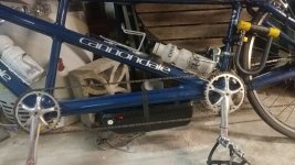
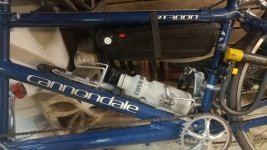
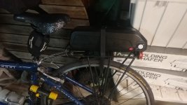
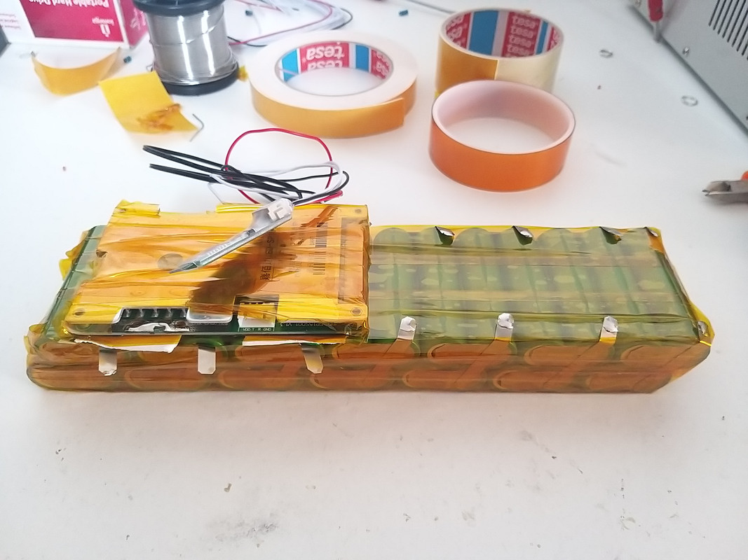
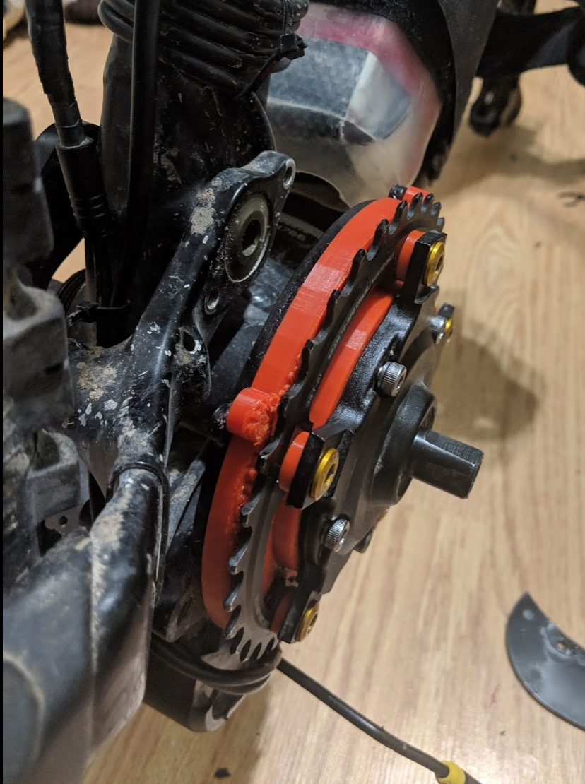
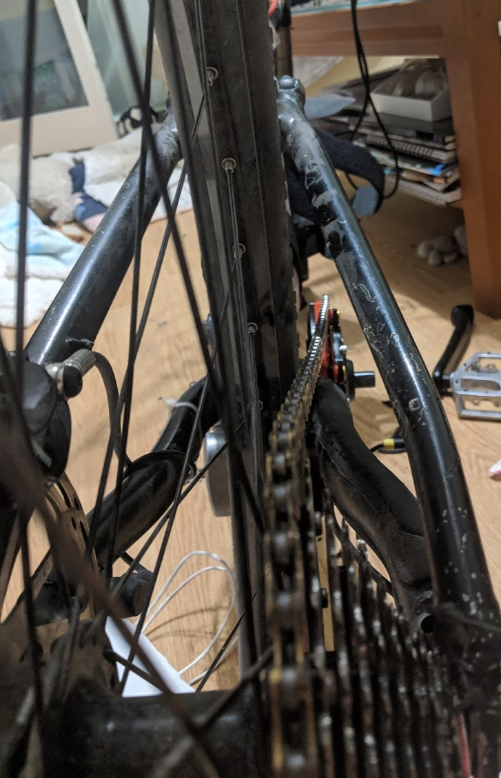
New "TSDZ2 Torque Sensor Central Motor"

RicMcK said:
I am trying to put a TDSZ2 on my tandem,and I need a longer spindle on the non drive side (the side where I motor is. There is not enough clearance for the linking chain ring spider. I need a spindle that is longer on the motor side, by about 1/4" or so. See photos.

Does anyone have any suggestions?

This fat bike adapter seems longer than what you need but might give you some ideas.

https://www.electrifybike.com/store/p68/TSDZ2-Fat-Bike-Adapter.html
 
RicMcK said:
Good ldea. But can it work with a 68mm BB?

Yes, it can work. I do this with 100mm BBSHD motors on 68mm BB tandem bikes. 68mm BBS02 motors will actually clear the spider on the left side.

You will need to space it out with BB spacers to install the bracket. I have some 10mm spacers. PM me if you need some. Eco-cycles has a 92mm extension kit that will make it so you don't need quite as many spacers. https://www.eco-ebike.com/collectio...on-in-92mm-100mm-120mm?variant=21167752577106
 
Hi,

Are there any outcoming wires that are constantly having 3,3v or 5v , even when the motor is turned off ?
I am building a battery and would like to add GPS tracking, but not sure should i add it directly to battery (need to decrease voltage) or i can get power to GPS from motor.
 
Peetsyo said:
Hi,

Are there any outcoming wires that are constantly having 3,3v or 5v , even when the motor is turned off ?
I am building a battery and would like to add GPS tracking, but not sure should i add it directly to battery (need to decrease voltage) or i can get power to GPS from motor.
I think you have only the battery voltage on the wires, never other voltage on the wires.

I would add GPS on the battery pack as it is kind of dangerous, expensive, and so I guess a thief would try to avoid remove/damage it, contrary to a display.

I am building a 350Wh battery pack right now, with 14S2P, 52V 3500mAh cells and weights 1.5kg:

IMG-20190728-104657.jpg


Can you share what device and/or service will you use for location??
 
I was testing the pedal human power reading and at startup, when I put my weight on the pedals, I got max value of 1050 watts!! As you can see on the graph (it averages the values on 3.5 seconds window so it does not show that peak of 1050 but shows a little less). The values more constant on the graph were about 100 up to 150 watts while I was riding, only on startups If I put a lot of force I could go to this high values of 1000 watts:

image.png


Validation:
- I verified before start this tests that the torque sensor was correctly measuring my weight of 102 kgs
- the formula is:
pedal_torque_x100 = torque_sensor_weight * (uint16_t) TORQUE_SENSOR_WEIGHT_TO_FORCE_X100;
pedal_torque_x100 = 102 kgs * 167
pedal_torque_x100 = 17034

pedal_power_x10 = pedal_torque_x100 * pas_cadence_rpm) / 96
pedal_power_x10 = (17034 * 60) / 96
pedal_power_x10 = 10646
pedal_power = 1064 watts!!

Hmmm, but there is one important note here!! the 1050 watts are instantaneous values and not the average of my human power... as we know, we should get a kind of sinewave shape on the pedal torque...

Force (Nm) = weight Kg * 9.81 * 0.17 (0.17 = arm cranks size)
---------------------------------------------------------*/
#define TORQUE_SENSOR_WEIGHT_TO_FORCE_X100 167

// (2 * pi) / (60 * 10) = 0.010466667
// 1 / 0.010466667 = 96
 
casainho said:
Peetsyo said:
Hi,

Are there any outcoming wires that are constantly having 3,3v or 5v , even when the motor is turned off ?
I am building a battery and would like to add GPS tracking, but not sure should i add it directly to battery (need to decrease voltage) or i can get power to GPS from motor.
I think you have only the battery voltage on the wires, never other voltage on the wires.

I would add GPS on the battery pack as it is kind of dangerous, expensive, and so I guess a thief would try to avoid remove/damage it, contrary to a display.

I am building a 350Wh battery pack right now, with 14S2P, 52V 3500mAh cells and weights 1.5kg:

IMG-20190728-104657.jpg


Can you share what device and/or service will you use for location??

Hi Casainho,

Nice design Battery.

I am thinking to do the same 14S2P but with 21700, 4900mAh SAMSUNG INR21700-50E with max 9,8A continuous discharge Current.
It´s about 500Wh.
Total 2kg with BMS.

What is the max current I can configured TSDZ2 Motor with this battery? Do you think Maximum current 18A it´s ok?

I´m going to have 2 batteries in parallel when I need to do more KM. (1000Wh total)

Of course with two batteries, in parallel, 18A it´s ok, with no problem.

I´m doing a second full suspension bike, now it is for me. With TSDZ2.
The other one I have is my wife´s bike.

Now it´s an Giant Trance 27,5 with 2,6 (or 2,35) tires front and rear.

It´s a Trail bike with 140mm travel front and Rear.

Best Regards
 

Attachments

  • Trance 2 LTD 27.5 2014 só foto.jpg
    Trance 2 LTD 27.5 2014 só foto.jpg
    66.4 KB · Views: 2,098
I'm making a thinner gear cover to get a few more milimeters on the chainline. Prototype is 1mm thick, and the spacers for the chainring are 3.2mm so it's 3.2mm closer. Still need to shave a few tenths off the cover or make the spacers thinner as it rubs a bit. Maybe I can put it around 0.2-0.5mm closer to the gear but that's probably on the limit already. Could get about 0.5mm more if I could get flush bolts for the chainring.
vZ43oF8.png

7Pobh6E.png


Chainline:
vDZ0L7b.png


Chainring is 34t SRAM, zero offset. Top 3 gears were useless with stock cover as the chain was very sideways. Hopefully this will bring shifting closer to the original 42t (which has 5mm offset I think)
 
btslo said:
I'm making a thinner gear cover to get a few more milimeters on the chainline. Prototype is 1mm thick, and the spacers for the chainring are 3.2mm so it's 3.2mm closer. Still need to shave a few tenths off the cover or make the spacers thinner as it rubs a bit. Maybe I can put it around 0.2-0.5mm closer to the gear but that's probably on the limit already. Could get about 0.5mm more if I could get flush bolts for the chainring.
vZ43oF8.png

7Pobh6E.png


Chainline:
vDZ0L7b.png


Chainring is 34t SRAM, zero offset. Top 3 gears were useless with stock cover as the chain was very sideways. Hopefully this will bring shifting closer to the original 42t (which has 5mm offset I think)

Nice work
 
andrea_104kg said:
I have a digital thermometer connected to the motor, no connections to the control unit, I monitor the temperature manually. I noticed that the greatest increase in temperature occurs at high speeds uphill, even not too steep climbs, but faced at speed with long ratios. It also depends on whether the engine is already warm when we tackle the climb. With my 48v if the engine temperature is 70 degrees and I face a climb of 8% at maximum power, it takes less than one km to see on the display of the thermometer 104 degrees. Obviously it is a very dangerous temperature, also because it is detected outside the engine, inside it is certainly higher. If you then insist on facing climbs because you do not know the engine temperature, burning is safe. I recently made a rather radical change by putting copper fins on the engine and I noticed an incredible improvement. It is not only the presence of the fins but now the whole left part of the engine heats up, while before it remained barely warm and this removes so much heat from the engine. The heating phase is very long, on quiet routes the engine never manages to reach over 70 degrees. only with extreme paths it reaches about 85 degrees and goes down very quickly while with the original engine the descent of the tempreatura was very slow.
In the picture you can't see but I closed the holes with heat-resistant silicone
I may have overheated the motor during series of 0.5-1km 5-6% climbs at 12-16km/h, although the right side part of the casing was barely warm at 24C ambient temperature when checking by touch with total weight around 105kg.
 
btslo said:
I'm making a thinner gear cover to get a few more milimeters on the chainline. Prototype is 1mm thick, and the spacers for the chainring are 3.2mm so it's 3.2mm closer. Still need to shave a few tenths off the cover or make the spacers thinner as it rubs a bit. Maybe I can put it around 0.2-0.5mm closer to the gear but that's probably on the limit already. Could get about 0.5mm more if I could get flush bolts for the chainring.
vZ43oF8.png

7Pobh6E.png


Chainline:
vDZ0L7b.png


Chainring is 34t SRAM, zero offset. Top 3 gears were useless with stock cover as the chain was very sideways. Hopefully this will bring shifting closer to the original 42t (which has 5mm offset I think)

If this works, I’d like to buy one from you. I have the same issue, but reduced my rears cassette from 10 gears to 8. Shifting is ok, but I’d like to get back to 10 gears.
 
AZUR said:
I am thinking to do the same 14S2P but with 21700, 4900mAh SAMSUNG INR21700-50E with max 9,8A continuous discharge Current.
It´s about 500Wh.
Total 2kg with BMS.

What is the max current I can configured TSDZ2 Motor with this battery? Do you think Maximum current 18A it´s ok?

I´m going to have 2 batteries in parallel when I need to do more KM. (1000Wh total)
I didn't know about that cells and they are available on Nkon, the same place I bough mine: https://eu.nkon.nl/rechargeable/21700-20700-size/samsung-inr21700-50e.html
2 kgs for 500Wh seems very good!! And having 1000Wh... once I used 900Wh for riding 90kms and +3000m of climbing and I wish I will never do such effort in my life again, so, 1000Wh should be for a long trip :)

Mine are also 10A rated to continuous discharge current. My friend that do this packs, professionally for motorcycles, ebikes and small cars, tells me to use no more than 1/3 of this current.

I am configuring max current to 8A and so that is 4A for each cell and so that is 1/2.5.
 
ERROR IN BATTERY VOLTAGE READING for 36V battery.
Hi all i have noted that there is an error in voltage reading. with the battery full just disconnected from the cahrger i measue with my fluke multimeter 42V instead on lcd03 display i only see 41V.
I have done this measurements with the bike switched on but stopped so the internal resistance doesn't affect the measure because the current drained from battery is very low.
I have installed the last 0.19.0 version.
Best regards

Maurizio
 
RicMcK said:
I am trying to put a TDSZ2 on my tandem,and I need a longer spindle on the non drive side (the side where I motor is. There is not enough clearance for the linking chain ring spider. I need a spindle that is longer on the motor side, by about 1/4" or so. See photos.

Does anyone have any suggestions?

Put the linking chain on the right side, using some road cranks:

IMG_2993.jpeg

IMG_2771.jpeg

IMG_2995.jpeg

IMG_3353.jpg

IMG_3354.jpeg
 
Hi

I'm trying to take off the chainring. I removed all 5 screws, but it won't budge, what am I missing?

Is there a lockring hidden behind the center gasket or something?
 
Bartman said:
btslo said:
I'm making a thinner gear cover to get a few more milimeters on the chainline. Prototype is 1mm thick, and the spacers for the chainring are 3.2mm so it's 3.2mm closer. Still need to shave a few tenths off the cover or make the spacers thinner as it rubs a bit. Maybe I can put it around 0.2-0.5mm closer to the gear but that's probably on the limit already. Could get about 0.5mm more if I could get flush bolts for the chainring.
vZ43oF8.png

7Pobh6E.png


Chainline:
vDZ0L7b.png


Chainring is 34t SRAM, zero offset. Top 3 gears were useless with stock cover as the chain was very sideways. Hopefully this will bring shifting closer to the original 42t (which has 5mm offset I think)

If this works, I’d like to buy one from you. I have the same issue, but reduced my rears cassette from 10 gears to 8. Shifting is ok, but I’d like to get back to 10 gears.

I too am interested in this, and may want 2 of them.
 
Maurizio said:
RicMcK said:
I am trying to put a TDSZ2 on my tandem,and I need a longer spindle on the non drive side (the side where I motor is. There is not enough clearance for the linking chain ring spider. I need a spindle that is longer on the motor side, by about 1/4" or so. See photos.

Does anyone have any suggestions?

Put the linking chain on the right side, using some road cranks:

IMG_2993.jpeg

IMG_2771.jpeg

IMG_2995.jpeg

IMG_3353.jpg

IMG_3354.jpeg
Thanks yes I though of this, but I really need 2 chainrings for More gears.
 
You are correct. :) I can add the spider to the "drive side" and still have room for the dual chainrings :) This easy as the Captain cranks are "normal" crank arms (with the peddle spindles reversed). I can now flip the captain crank arms to be "proper". Now I only need to solve the batter mounting placement (photos to follow)
 
andrea_104kg said:
dameri said:
andrea_104kg said:
However the dimensions of the motor shaft are ridiculous, you can see in the picture the comparison with a pen. As you can see, I am an engine burn expert, the neighbor is the rotor of a bpm hub :D :D

I agree, little bigger more durability. I don't care very much for weight, because it's electric bike. Exept when I carry my bike to my carage which is on the third floor (home).

I also think that the engine is really undersized, the minimum possible. The bafang bpm have more solid engines.
Unfortunately we have to be content with this, which makes miracles so small it is

This is a 350watt motor. It is not originally designed to take 750+ Watts.
 
RicMcK said:
You are correct. :) I can add the spider to the "drive side" and still have room for the dual chainrings :) This easy as the Captain cranks are "normal" crank arms (with the peddle spindles reversed). I can now flip the captain crank arms to be "proper". Now I only need to solve the batter mounting placement (photos to follow)

Remember to check the chain line between the captain and the stoker chain rings, as the motor puts the stoker one pretty outside the optimal line.
 
casainho said:
Peetsyo said:
Hi,

Are there any outcoming wires that are constantly having 3,3v or 5v , even when the motor is turned off ?
I am building a battery and would like to add GPS tracking, but not sure should i add it directly to battery (need to decrease voltage) or i can get power to GPS from motor.
I think you have only the battery voltage on the wires, never other voltage on the wires.

I would add GPS on the battery pack as it is kind of dangerous, expensive, and so I guess a thief would try to avoid remove/damage it, contrary to a display.

I am building a 350Wh battery pack right now, with 14S2P, 52V 3500mAh cells and weights 1.5kg:

IMG-20190728-104657.jpg


Can you share what device and/or service will you use for location??

I have ordered that one:
https://www.aliexpress.com/item/32816659991.html?spm=a2g0s.8937460.0.0.2fbe2e0eXvKqAQ

My battery is very thight , inside a home-made fiberglass case 14S3P. I had no option , because it is a DH bike.
My heart was dripping when I drilled holes into the brandnew (but old version) bike frame, but I knew that I was never going to pedal this thing manually :)
 

Attachments

  • 20190729_234127.jpg
    20190729_234127.jpg
    56.9 KB · Views: 1,873
  • 20190303_231850.jpg
    20190303_231850.jpg
    149.9 KB · Views: 1,873
With the help of the community I have a plan for the motor and chainring ect. Thank you :D.

My new question is about mounting the battery. I want to use the same battery I am already have, as I don't need 2 batteries as I can only ride one bike at a time. Sadly the battery is about 1.5cm too long to fit in the front or lower triangle. I opened up the case and there is no space to cut out. I could remove the 2 bottle cages in the upper stoker triangle but we need them for water.

My ideas are that I could put it on the bottom of the cross tube, the bottom of the stoker top tube, or the rear rack. If I mount it upside down I will add some secondary straps to secure it. Do you think it would be OK on the bottom cross tube? I wonder if there is enough ground clearance.
 

Attachments

  • 19-07-29_3.37.36PM-1328x747.jpg
    19-07-29_3.37.36PM-1328x747.jpg
    167 KB · Views: 1,854
  • 19-07-29_3.39.08PM-1328x747.jpg
    19-07-29_3.39.08PM-1328x747.jpg
    167.7 KB · Views: 1,854
  • 19-07-29_3.39.59PM-1328x747.jpg
    19-07-29_3.39.59PM-1328x747.jpg
    138.8 KB · Views: 1,854
btslo said:
I'm making a thinner gear cover to get a few more milimeters on the chainline. Prototype is 1mm thick, and the spacers for the chainring are 3.2mm so it's 3.2mm closer. Still need to shave a few tenths off the cover or make the spacers thinner as it rubs a bit. Maybe I can put it around 0.2-0.5mm closer to the gear but that's probably on the limit already. Could get about 0.5mm more if I could get flush bolts for the chainring.
vZ43oF8.png

7Pobh6E.png


Chainline:
vDZ0L7b.png


Chainring is 34t SRAM, zero offset. Top 3 gears were useless with stock cover as the chain was very sideways. Hopefully this will bring shifting closer to the original 42t (which has 5mm offset I think)
Great work. What are you printing it in? 1mm is pretty thin if PLA? What printer and res?

Cheers
 
I put an ISM Sport saddle on my Trek navigator 400 project. It got the saddle far enough back I could finally ride the 14" frame bike. The Nexus 7 IGH skips in top gear. I guess one of the roller clutches can't hold the power. I'm having a Nexus 8 speed IGH installed in the Trek wheel. I also ordered the display and motor controller to add throttle and open source firmware. I'm hoping to get my hands on a burnt up motor to see what I can come up with for a cooling mod. I'm in the US so they're hard to find around here.
 
RicMcK said:
With the help of the community I have a plan for the motor and chainring ect. Thank you :D.

My new question is about mounting the battery. I want to use the same battery I am already have, as I don't need 2 batteries as I can only ride one bike at a time. Sadly the battery is about 1.5cm too long to fit in the front or lower triangle. I opened up the case and there is no space to cut out. I could remove the 2 bottle cages in the upper stoker triangle but we need them for water.

My ideas are that I could put it on the bottom of the cross tube, the bottom of the stoker top tube, or the rear rack. If I mount it upside down I will add some secondary straps to secure it. Do you think it would be OK on the bottom cross tube? I wonder if there is enough ground clearance.
Maybe remove the plastic sheel of the box it will work? You can always do you sheel with same good material like sponge and then strong black tape as I do.
 
Back
Top