You are using an out of date browser. It may not display this or other websites correctly.
You should upgrade or use an alternative browser.
You should upgrade or use an alternative browser.
APL's DIY axial-flux motor
- Thread starter APL
- Start date
APL
100 kW
- Joined
- Aug 6, 2018
- Messages
- 1,113
Maybe I can sell it as a brake for a Bullet Train. 
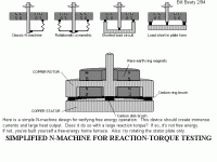
Interesting stuff, reminds me of Faradays homopolar generator, and furnace, and gets back to the basics
of everything electric.
I've always wondered if a stacked version of the so called N-machine, with modern magnets, would make a
good wind mill powered furnace. Direct conversion of wind to heat.
Interesting stuff, reminds me of Faradays homopolar generator, and furnace, and gets back to the basics
of everything electric.
I've always wondered if a stacked version of the so called N-machine, with modern magnets, would make a
good wind mill powered furnace. Direct conversion of wind to heat.

APL
100 kW
- Joined
- Aug 6, 2018
- Messages
- 1,113
Caught a summer cold this week, so I was out for a while, but was back in the shop today and machined
out the bearing cap clearance for the new bearing. Spin's real nice now.
When I put it all back together, I left out all the cores so I could get a feel for how much resistance the
rotors would have with just the aluminum stator plates alone. Spinning it by hand, I'd have to say, it was
not very much resistance. It would spin for one or two turns, and didn't have all that much drag to it.
Then I put it on the test stand that way, and spun it up to 295 rpm for five minutes. The cold start temperature
was 84.2 degrees, and after 5 min. it climbed to 88.3.
So, it doesn't appear to be much of a problem at the moment, and certainly won't keep the motor from running,
but will have to be addressed at some point down the road, with non ferrous plates. All heat is unwanted.
Next, I wound a couple of cores with the new 14 awg solid wire, and installed a couple of multi strand cores in
the stator assembly, so I could get a comparison test between the four of them.
After spinning them up in the test stand at 280 rpm, I got a reading of .347v (347. mv) and , .322v on the two
solid strand coils, and .349v / .324v on the multi strand coils.
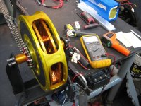
Not enough difference to worry about, which is a good thing, and clears the way for winding all the coils with 14 awg.
They certainly look more robust, and don't seem to have a problem with shorts.
If I average the coil outputs to .330v each, and multiply it times seven, for each phase set, I get an estimated 2.310v
at 280 rpm., which would seem to be an improvement over the last test I did, at the end page 13.
Maybe theres hope,.. but I'm not going to get too excited yet. :wink:
I'll wind up all the coils, and give it another try.
out the bearing cap clearance for the new bearing. Spin's real nice now.
When I put it all back together, I left out all the cores so I could get a feel for how much resistance the
rotors would have with just the aluminum stator plates alone. Spinning it by hand, I'd have to say, it was
not very much resistance. It would spin for one or two turns, and didn't have all that much drag to it.
Then I put it on the test stand that way, and spun it up to 295 rpm for five minutes. The cold start temperature
was 84.2 degrees, and after 5 min. it climbed to 88.3.
So, it doesn't appear to be much of a problem at the moment, and certainly won't keep the motor from running,
but will have to be addressed at some point down the road, with non ferrous plates. All heat is unwanted.
Next, I wound a couple of cores with the new 14 awg solid wire, and installed a couple of multi strand cores in
the stator assembly, so I could get a comparison test between the four of them.
After spinning them up in the test stand at 280 rpm, I got a reading of .347v (347. mv) and , .322v on the two
solid strand coils, and .349v / .324v on the multi strand coils.

Not enough difference to worry about, which is a good thing, and clears the way for winding all the coils with 14 awg.
They certainly look more robust, and don't seem to have a problem with shorts.
If I average the coil outputs to .330v each, and multiply it times seven, for each phase set, I get an estimated 2.310v
at 280 rpm., which would seem to be an improvement over the last test I did, at the end page 13.
Maybe theres hope,.. but I'm not going to get too excited yet. :wink:
I'll wind up all the coils, and give it another try.
APL
100 kW
- Joined
- Aug 6, 2018
- Messages
- 1,113
The motor gods are still angry with me,.. even after all the effort I've put into it.
Rewound all the coils with 14 awg, did a super job of wiring them all together,.. didn't have any
ground shorts, made absolutely sure that the coil poles are correct, and put it all back together.
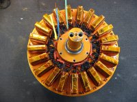
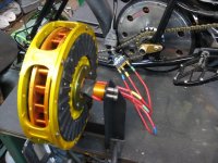
After putting it back in the test stand and hooking it up to the controller,.. it turns slowly for about
one turn,.. clicks and ratchets while it's doing it, and then the controller shuts down on an overload of
some sort.
When I release the throttle, and twist it again, it will reset and start over.
Pretty much the same as before. I can change the direction though, so at least it's trying.
I was able to reverse a rotor, and run it on one side, but the result was exactly the same.
Well, it took Edison a thousand try's to invent the light bulb, so I guess I can endure a little failure.
I'll re-run coil outputs tomorrow, but clearly something is basically amiss. I know I have way too much
core steel in the coils,.. like twice as much as I should have, which is probably causing most of the the drag.
Could be one reason.
This is what the core should look like.
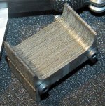
I have to question how many winds I have in the copper as well. It Just seems to be less than most motors,
Have I missed something here? Seems like there should be twice as much?
I should start looking for a decent ohm meter, so I can find out where I'm at on that.
And lastly, perhaps I should wire each phase in a series pattern, like 90 percent of motor design's,.. Maybe this
pattern doesn't transfer well to an axial design.
Any other suggestions?
Rewound all the coils with 14 awg, did a super job of wiring them all together,.. didn't have any
ground shorts, made absolutely sure that the coil poles are correct, and put it all back together.

After putting it back in the test stand and hooking it up to the controller,.. it turns slowly for about
one turn,.. clicks and ratchets while it's doing it, and then the controller shuts down on an overload of
some sort.
When I release the throttle, and twist it again, it will reset and start over.
Pretty much the same as before. I can change the direction though, so at least it's trying.
I was able to reverse a rotor, and run it on one side, but the result was exactly the same.

Well, it took Edison a thousand try's to invent the light bulb, so I guess I can endure a little failure.
I'll re-run coil outputs tomorrow, but clearly something is basically amiss. I know I have way too much
core steel in the coils,.. like twice as much as I should have, which is probably causing most of the the drag.
Could be one reason.
This is what the core should look like.

I have to question how many winds I have in the copper as well. It Just seems to be less than most motors,
Have I missed something here? Seems like there should be twice as much?
I should start looking for a decent ohm meter, so I can find out where I'm at on that.
And lastly, perhaps I should wire each phase in a series pattern, like 90 percent of motor design's,.. Maybe this
pattern doesn't transfer well to an axial design.
Any other suggestions?
larsb
1 MW
I guess it's a wiring error somewhere, not cores or turn count, it would still turn. It generates volts when you spin it as a generator, right? That's proof of concept if it does.
Can you check with other controllers? this one can be a poor match or even broken..
Next step is to somehow get an oscilloscope i guess
Can you check with other controllers? this one can be a poor match or even broken..
Next step is to somehow get an oscilloscope i guess
Too bad that it doesn't spin now with the redone winding., man it seems like this motor is a drama queen!
I think the problem more likely could be that your coils have rectangular shape and the magnets too which both lead to a very low coverage.
If you rebuild one part to trapezoidal it should improve things a lot in this regard :wink:
The winding sheme or slot/pole count seems to be quite uncommen, right, so couldn't it be that there is generally something wrong with it?
The copper fill looks not bad or at least it definitely should not prevent the motor from spinning.APL said:I have to question how many winds I have in the copper as well. It Just seems to be less than most motors,
Have I missed something here? Seems like there should be twice as much?
I should start looking for a decent ohm meter, so I can find out where I'm at on that.
I think the problem more likely could be that your coils have rectangular shape and the magnets too which both lead to a very low coverage.
If you rebuild one part to trapezoidal it should improve things a lot in this regard :wink:
And lastly, perhaps I should wire each phase in a series pattern, like 90 percent of motor design's,.. Maybe this
pattern doesn't transfer well to an axial design.
Any other suggestions?
The winding sheme or slot/pole count seems to be quite uncommen, right, so couldn't it be that there is generally something wrong with it?
Very nice assembly APL. Looks great
but,
I'm quite skeptical when I look at the slotted metallic mounting plates for the coils on each side... I think the conductive path around the coil is cancelling the magnetic field. You end up with an heating element instead of a motor.
I would try with non conductive mounting plates for the coils instead and it should spin way better. (fiberglass reinforced with epoxy resin mounting plate would be stiff enough I think)
larsb
1 MW
You're like three pages late with that comment to be first 
It produces good voltage on all three phases when spun with a drill though, right? So the magnetics shouldn't be *that* bad?
If you spin it as a generator and connect the phase leads to another motor (in the correct order) the slave motor should spin? That might tell you something (although perhaps not much) about the waveform?
Maybe there's just something characteristic about it the sensorless controller just doesn't like?
If nothing else it looks awesome though 8)
APL
100 kW
- Joined
- Aug 6, 2018
- Messages
- 1,113
Thanks for the comments guys, it really helps to get your opinions. :thumb:
I'll do another phase output test soon, and I decided that it would be a good idea to do the same test on the
Crystalyte motor that I'm using now, and see what that has for phase outputs. If I can match the outputs to
each other, I should at least be in the ball park?
I'll dig around for an oscilloscope, I know theres one gathering dust somewhere,.. not sure about the quality though.
The controller works fine, I use it every day on the bike it's on, but whether or not it's a match for this motor
is a good question. I know it has the power capacity, but maybe another type, or a sinusoidal would be better.
I hate to start wallowing around in different controllers at this point though, $$$ave it for later?
Sadly, I don't know a whole lot about them, so your help would be greatly appreciated here.
Those plates are going to get cut dang it!!! Kill that theory once and for all. But not quite yet,.. theres still a
few things to explore.
So, I guess next is to measure the two motor's phase outputs, and see what's up with that, and then probably rewire
the coils in a standard pattern,.. that is ABC,ABC,ABC, all the way around, and see what happens when thats done.
OK,.. then neuter the plates.
Do some of the easiest things first, then go back and mill the cores if need be. Going trapezoidal is the most efficient
way, and most motors are made that way, but that would require going back to the beginning and basically starting
over, which I'm quite willing to do, but I would hope that this motor will still give me more than one turn yet.
Whatever it takes, I must have redemption!
I'll do another phase output test soon, and I decided that it would be a good idea to do the same test on the
Crystalyte motor that I'm using now, and see what that has for phase outputs. If I can match the outputs to
each other, I should at least be in the ball park?
I'll dig around for an oscilloscope, I know theres one gathering dust somewhere,.. not sure about the quality though.
The controller works fine, I use it every day on the bike it's on, but whether or not it's a match for this motor
is a good question. I know it has the power capacity, but maybe another type, or a sinusoidal would be better.
I hate to start wallowing around in different controllers at this point though, $$$ave it for later?
Sadly, I don't know a whole lot about them, so your help would be greatly appreciated here.
Those plates are going to get cut dang it!!!
few things to explore.
So, I guess next is to measure the two motor's phase outputs, and see what's up with that, and then probably rewire
the coils in a standard pattern,.. that is ABC,ABC,ABC, all the way around, and see what happens when thats done.
OK,.. then neuter the plates.
Do some of the easiest things first, then go back and mill the cores if need be. Going trapezoidal is the most efficient
way, and most motors are made that way, but that would require going back to the beginning and basically starting
over, which I'm quite willing to do, but I would hope that this motor will still give me more than one turn yet.
Whatever it takes, I must have redemption!
larsb
1 MW
If ABC winding works with your slot and pole count according to the winding calculators then try it, otherwise it's a certain fail.
I don't mean you need a different esc, only that it could be wise to try another one and rule that out.
I guess the generator test will show something. :wink:
I don't mean you need a different esc, only that it could be wise to try another one and rule that out.
I guess the generator test will show something. :wink:
APL said:free energy shit
What the hell? The guy that built this beautiful looking motor is one of these people? No wonder he can't get it to work.
thepronghorn
1 kW
flat tire said:APL said:free energy shit
What the hell? The guy that built this beautiful looking motor is one of these people? No wonder he can't get it to work.
Note he said wind to heat generation, so I'm pretty sure he realizes that the energy isn't free free.
APL
100 kW
- Joined
- Aug 6, 2018
- Messages
- 1,113
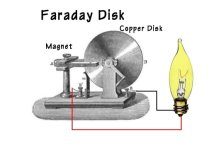
I was afraid that people might get that impression from the photo. I tried to find a picture of
Michale Faraday's induction furnace, but it's rare, and the print above is basically the same thing,
a shorted out homopolar generator,.. or what we just call a shorted generator, which of course,
is going to do nothing but create heat.
Theres a way to do it without using any brushes,.. just magnets spinning past thick copper plate's,
which would be perfect for wind, or hydro, as theres nothing to wear out. It would make heat for years.
It will defiantly take lots of power to run it though.
A few years ago, I even started to make one. I got the windmill part built, but a storm came along
and tore it apart, and scattered it all over the yard,.. about $300. bucks down the toilie hole.
Should have erased the print part, my bad. Not a free energy guy,.. nope, very expensive! :lol:
APL
100 kW
- Joined
- Aug 6, 2018
- Messages
- 1,113
A very unique machine, and my hat goes off to Michael Faraday for coming up with it.
Many people just look at it, and shrug it off.
If you truly understand whats going on here, it's an eye opener, and leads the way to other
interesting forms. It produces low voltage, but DC!!, and will create VERY high amps.
Check it out. https://en.wikipedia.org/wiki/Homopolar_generator
Many people just look at it, and shrug it off.
If you truly understand whats going on here, it's an eye opener, and leads the way to other
interesting forms. It produces low voltage, but DC!!, and will create VERY high amps.

Check it out. https://en.wikipedia.org/wiki/Homopolar_generator
APL said:not free energy guy
I was wrong about you. This is a nice project. My apologies.
stan.distortion
1 kW
- Joined
- Jun 12, 2019
- Messages
- 377
APL said:I was afraid that people might get that impression from the photo. I tried to find a picture of
Michale Faraday's induction furnace, but it's rare, and the print above is basically the same thing,
a shorted out homopolar generator,.. or what we just call a shorted generator, which of course,
is going to do nothing but create heat.
Theres a way to do it without using any brushes,.. just magnets spinning past thick copper plate's,
which would be perfect for wind, or hydro, as theres nothing to wear out. It would make heat for years.
It will defiantly take lots of power to run it though.
A few years ago, I even started to make one. I got the windmill part built, but a storm came along
and tore it apart, and scattered it all over the yard,.. about $300. bucks down the toilie hole.
Should have erased the print part, my bad. Not a free energy guy,.. nope, very expensive! :lol:
Better to use compressed fluid for a heat generating wind turbine (released pressure becomes heat), the energy can be transported to where its needed without thermal losses and the hardware is very simple, fixed displacement pump, pipe and a finely regulated tap (exponential rising output for wind power matches exponential rise of fluid pressure through an orifice).
Have you seen the Hantec oscilloscopes? About $20-40 for the low end PC models, fairly low spec but plenty good enough for most jobs and an absolute steal for the price.
wturber
1 MW
stan.distortion said:Have you seen the Hantec oscilloscopes? About $20-40 for the low end PC models, fairly low spec but plenty good enough for most jobs and an absolute steal for the price.
No. It is important that APL use a smartphone for this. :^)
https://www.youtube.com/watch?v=okP4a6NrhlQ
APL
100 kW
- Joined
- Aug 6, 2018
- Messages
- 1,113
Ha! I knew it! I was almost afraid that you were going to miss out on this one wturber. I thought,..
no way can you use a smart phone for an oscilloscope, but I was wrong. :x
Thanks stan.distortion, I looked around a little for the Hantek, but only found the more expensive models.
I did find plenty of other used oscilloscopes though, for fairly cheap. I'll probably get one,.. need to look
some more. The one I have here turned out to be an automotive unit, expressly for points and condensers.
No wonder it's gathering dust!
The compressed fluid idea sounds really good, and solves a lot of problems all at once. I like it, and will
have to look into it more. There 'is' a problem with a magnetic furnace in that magnets don't like heat,
so it would have limits, although some Neo's are made to withstand close to 300 degrees.
The compressor windmill could probably be made with all off the shelf parts as well,.. another big plus.
Keep in mind that the "shorted turn" caused by the aluminum frame won't be very significant at low frequencies like turning the rotor by hand, but at the PWM frequency of the controller it will look a lot more like a dead short. This is probably causing the controller to shut down.
APL
100 kW
- Joined
- Aug 6, 2018
- Messages
- 1,113
Good point, and another reason for cutting the slots. Well, it seems like the votes are in on that, so
I might as well do the dirty and try it. Easy enough to do,.. my only concern is that the set screws
will brake the aluminum when they're tightened down, but theres only one way to find out.
I can probably find a fix for it if they do. They have to be remade anyway, so I'll go for it.
I might as well do the dirty and try it. Easy enough to do,.. my only concern is that the set screws
will brake the aluminum when they're tightened down, but theres only one way to find out.
I can probably find a fix for it if they do. They have to be remade anyway, so I'll go for it.
larsb
1 MW
yey! good luck! :thumb:
Dui ni shuo de dui
10 kW
Before screwing up with your nice aluminum plate, maybe you could just build one out of wood just to see if it works better.
It doesn't need to handle a lot of torque or forces, it would only be a proof of concept running at low speed and low currents.
That should be very easy to build and cost almost nothing
It doesn't need to handle a lot of torque or forces, it would only be a proof of concept running at low speed and low currents.
That should be very easy to build and cost almost nothing
APL
100 kW
- Joined
- Aug 6, 2018
- Messages
- 1,113
Sorry Dui, ni shuo de dui, it's a little too late, the hack saw made a mess of it already.
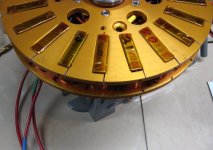
I have one side done, and it seems to be holding alright,.. a little spongy when I tighten the screws,
but it also serves to put pressure on the side of the core next to it, which helps to clamp it.
As long as it doesn't brake on the bottom on the slot, it should be good to go for a while.
They will need to be remade out of fiberglass board later on anyway. The only problem with that
is figuring out a way to hold the cores, as the little set screws won't work in glass board.
At that point I will probably switch to a more common pole count as well, and make up some new
back iron rings with slightly wider PM magnets to get a few mm's of overlap.
As madin88 expressed earlier, this is an unusual pole count, and the question was, that there might be
something wrong with it. I'm pretty sure that it has balance issues, which is why it has the unusual
wiring pattern.
I think one of the most common pole counts is the is the 9/12 motor, which when doubled is a 18/24.
Might be a better choice. It will have to be researched, but the cores are made, so a lesser count
would be relatively easy to make/convert.
Got to get this one to spin first though.
Well, my 5hp air compressor motor decided to crap out on me, so I'm in the middle of finding another
one of those $$$.
Always something!!!
Similar threads
- Replies
- 26
- Views
- 6,034
- Replies
- 14
- Views
- 725
- Replies
- 8
- Views
- 810

