Programming APT AE96600 controller from QSmotor

Status
Not open for further replies.

MJSfoto1956

10 kW
Joined
Jul 28, 2010
Messages
960
Location
Boston, MA
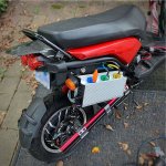
OMG. Being desperate, I ordered an APT AE96600 controller directly from QSmotor last week. Arrived last night. They programmed it specifically for my motor (or so they claimed) so it was basically "plug and play". What a difference! While the AE9600 is ridiculously too heavy and big for an eBike it fits just fine on my eScooter (see photo). And together with my updated Manual-cable-to-Hall-throttle it is smooth as can be. I can "feather" the throttle just like an ICE bike. I'll give it a real test run tomorrow. But so far, this is a keeper.

IMG_8580.1280.jpg
 
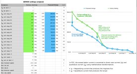
Not surprisingly, a little tweaking was in order. The AE96600 controller as programmed from the factory assumes you have a 300A BMS and that your battery pack can discharge gobs of power on demand. The 8000W V4 motor can handle it. The controller can handle it. But my battery pack was originally designed just to do errands and is constrained by both the battery cells (4.85Ah discharge max) and the BMS, which is limited to 150A. Needless to say, when I pushed the bike hard recently the BMS shut down when I was going up a hill. Sure enough, the controller was asking for more than 150A and the BMS did the right thing by shutting down. So with a bit of cajoling, I obtained the APT software and with advice from QSmotor made the following changes (Note: I typed all the parameters into a spreadsheet, thus the chart is of my own doing. This is not something from QSmotor):

Screen Shot 2019-08-12 at 12.04.46 PM.jpg

Now she runs fine (albeit a touch slower) and I don't expect to see much in the way of the BMS complaining going forward. However, sometime in the future I'm going to need a bigger battery + BMS! :p

M

P.S. does anyone know if the rather-obvious "dip" in the graph on the righthand side (between iqref 6 and iqref 12) is basically the "soft start" behavior? Note: I believe the chart should be read from right to left. i.e. max RPM on the far left and zero RPM on the far right. As such, this chart does not represent torque per se, but rather some sort of mapping for the behavior of torque compensation at various RPMs

P.P.S. for those looking for an explanation as to what iqref means, the following may help:

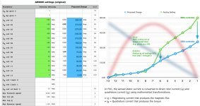
In FOC, the sensed stator current is converted to direct rotor current (Id) and quadrature current (Iq) using mathematical transformations.
  • Id = Magnetizing current that produces the magnetic flux
  • Iq = Quadrature current that produces the torque
 
It's not soft start. the different setpoints in the diagram are your max rpm divided in 13 steps, one setting for each RPM.
Don't see what soft start is in comparison with motors and their limitations - and the original settings are the opposite of soft start.

(What soft start could be is current limitation to save controller from overcurrent at low rpm)

Max power of a motor is at half noload RPM. I think the step at 6 is a way of making it easier on the controller.
Their settings set the phase current output a lot lower after half RPM and i guess reason is that current multiplication gets harder as the BEMF builds up. Since your max current is 150A it's probably logical to go below that at close to half noload.

Controller builders - what's your input?
 
larsb said:
Max power of a motor is at half noload RPM. I think the step at 6 is a way of making it easier on the controller. Their settings set the current conversion a lot lower after half RPM and i guess reason is that current multiplication gets harder as the BEMF builds up.

So what do "steps" mean in this regard?
After all, this is some sort of torque current mapping/compensation curve (iq = Quadrature current that produces the torque)
 
larsb said:
It's not soft start. the different setpoints in the diagram are your max rpm divided in 13 steps, one setting for each RPM.

Given that the changes recommended to me by QSmotor were to address the behavior of the bike at speed under load, I would assume then that the graph should be labeled horizontally left-to-right as: "Max RPM --> Zero RPM". So, is this curve some sort of mapping? If so, what is it mapping?
 
An example:
Max rpm=1300
Divide 1300 in 13 steps with setpoints at each 100rpm

Fill the lookup table with setpoints for max phase current output at each interval:
Iqref0 600A at 0rpm
Iqref1 600A at 100rpm
Iqref2 550A at 200rpm
..
Iqref13 xxxx at 1300rpm

Original settings are full blast at zero rpm, guess 600A might be a bit over the top for a hub. Then question is what they programmed for you? I guess phase angle and hall matching, possibly field weakening. Is the max rpm setting corresponding to your noload rpm? Otherwise the setpoints get screwed up.
 
larsb said:
An example:
Max rpm=1300
Divide 1300 in 13 steps with setpoints at each 100rpm

Fill the lookup table with setpoints for max phase current output at each interval:
Iqref0 600A at 0rpm
Iqref1 600A at 100rpm
Iqref2 550A at 200rpm
..
Iqref13 xxxx at 1300rpm

Original settings are full blast at zero rpm, guess 600A might be a bit over the top for a hub. Then question is what they programmed for you? I guess phase angle and hall matching, possibly field weakening. Is the max rpm setting corresponding to your noload rpm? Otherwise the setpoints get screwed up.

Yeah but that is precisely the opposite of what my issue was. My BMS was not cutting out at low RPM but high RPM. And that is what QSmotor asked me to change. Thus I go back to my original point: perhaps you are looking at the graph backward? With zero to the right, and full speed to the left?

M
 
No, since at higher rpm battery current is reaching phase current. If you have a bms with 150A cutoff then you need to be below this for the phase current setting at higher rpm.

- What they did was lower the current needed from the battery which only is a problem at higher rpms.

You can do a simple test:
set iqref1 to 50, iqref2 to 50 and iqref3 to 600, iqref4 to 50 etc.

I've done this, it's in my ae96600 thread. (Thought you read it since you posted in it?) what you get is exactly what i describe, low phase current up to iqref3 rpm where the motor takes off.
 
Maybe you can use grins motor simulator?

If you have enough info, you can make a custom motor.
Then just put in your max phase amps, 600?
And your max battery, 150.

Then compare with the same thing, but more battery amps.
Then it should be very clear at what rpm it is time to start limiting phase amps.
No need to "give away" low end torque

Be warned though, you will probably be very tempted to beef up the battery when you see what it can do :wink:
(Maybe look what more voltage too :shock: )
 
I've updated the diagram since it is extremely difficult reading data from right to left (which can't be changed in my spreadsheet, sorry). So I flipped it in a photo editor and superimposed a "traditional" torque/power graph on top so that it is more apparent what the changes that QSmotor suggested are likely doing: which in essence is reducing the phase Amp load from mid-RPM onward -- which is precisely what I experienced. I imagine this affects the amount of FOC as well, since this is a FOC controller.

Screen Shot 2019-08-02 at 9.34.05 PM.2500.jpg

M
 
larsb said:
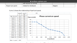
Or read the manual from advpower in my ae96600 thread.
image.png

Ok then. Perhaps this is a case of "my bad". Maybe I learned something, maybe not...

OTOH, the "conventional wisdom" regarding what this curve actually means (as documented) doesn’t make sense to me, as I'm sure it doesn't to many others.

No worries, the suggestion changes from QSmotor works and that’s enough for me for now.
 
I wonder why you have to play with phase amps and not just set a battery current limit, or do these controllers have no such setting?

If the BMS can do 150A then i would set it to 140A to be safe and max phase amps to 600A.

I mean this big motor can take such high amps, and even if you have just 140A battery the controller still could convert this to 600A phase during acceleration from a stand still up to a given speed.
 
DC current can be set. I guess 13 steps phase current setting has to do with the detailed flux weakening settings as you can set that also in 13 steps.

(Not that it's needed for current limiting for mjsfoto but reason it's in the program)

Cheers
 
larsb said:
(Not that it's needed for current limiting for mjsfoto but reason it's in the program)

Are you suggesting that QSmotor's recommendation was wrong? If so, then why? If not, then why make the accusation? I'm not understanding your point here.
 
MJSfoto1956 said:
Ok then. Perhaps this is a case of "my bad". Maybe I learned something, maybe not...

OTOH, the "conventional wisdom" regarding what this curve actually means (as documented) doesn’t make sense to me, as I'm sure it doesn't to many others.

No worries, the suggestion changes from QSmotor works and that’s enough for me for now.

Do you understand why at full throttle and no load your motor reaches a maximum rpm?

If you do then you will understand that the bemf generated by the motor at max rpm is more or less equal to the highest rms sin wave your controller can produce.

Under those circumstances can you explain how the controller is supposed to drive 600 amps phase current into the motor when there is essentially zero net voltage between the bemf and what the controller can produce bearing in mind at the crudest level ohms law?

I hope you can see that driving 600 amps into your motor at a voltage limited maximum rpm operating point is an impossibility and that is why the graph is shown correctly in the manual and makes perfect sense. At zero rpm bemf is also zero so there is plenty of voltage available to drive current into the motor. Since the motor is also a generator the ability to drive current into it plainly decreases with every increase in rpm.
 
MJSfoto1956 said:
larsb said:
(Not that it's needed for current limiting for mjsfoto but reason it's in the program)

Are you suggesting that QSmotor's recommendation was wrong? If so, then why? If not, then why make the accusation? I'm not understanding your point here.

The way all other controllers i've programmed work is that you set max DC current from battery, set max phase current and that's it - controller takes care of the rest.

You can set DC current in AE96600 program and that should stop any cutouts due to BMS shutdown. I think reason for the phase current setting in 13 steps is to be able to set field weakening and phase current separately at different rpms which is useful for IPM motors. But if you have a conventional motor i don't know why you would need to do it, phase current limiting should be handled by the controller.

Either it works like this or program is not well designed so that controller will fault if asked to give 600A phase at full rpm or it will allow higher DC current if phase current requested needs it - either way it's a poor implementation.
..It should not be needed to set the phase current other than to 600A if your motor can take it.

I've set controller phase current at 600A for all of the set points and drove a very short bit, then i got hall sensor issues in motor (not related to the setting). I could not test it out further due to the motor issue so i don't know how it behaves..

Reason i asked you to remove the post is that it doesn't contribute good data, instead it's misleading.
I also wonder why you mix in the "soft start", "quadrature current" explanation etc when you're actually not certain what you write. (if you would know it, then you'd understand the setting graph). Better to be a bit low key and stick with what you know, no pun intended - it will benefit all reading at ES.
 
kiwifiat said:
I hope you can see that driving 600 amps into your motor at a voltage limited maximum rpm operating point is an impossibility and that is why the graph is shown correctly in the manual and makes perfect sense. At zero rpm bemf is also zero so there is plenty of voltage available to drive current into the motor. Since the motor is also a generator the ability to drive current into it plainly decreases with every increase in rpm.

Yeah the diagram is OK as it was and needs to be read from left to right. It is showing what happens when accelerating from a dead stop.

@ MJSfoto
600A phase should be no problem in theory even with less than 150A battery, so why you don't just set it up like this and try it out? :mrgreen:

During acceleration the controller will first operate at phase amp limit (max torque), then after a given speed it will operate at battery current limit (max power).
The faster you get the higher BEMF (generator voltage) will become and the lower the phase amps, and if full speed is reached in an optimal case the controller should operate below any set limits, at least if you go WOT on the flat.

Thats how it works if motor + controller + battery (with BMS) has been properly selected and designed.
 
kiwifiat said:
Do you understand why at full throttle and no load your motor reaches a maximum rpm?

If you do then you will understand that the bemf generated by the motor at max rpm is more or less equal to the highest rms sin wave your controller can produce.

Under those circumstances can you explain how the controller is supposed to drive 600 amps phase current into the motor when there is essentially zero net voltage between the bemf and what the controller can produce bearing in mind at the crudest level ohms law?

I hope you can see that driving 600 amps into your motor at a voltage limited maximum rpm operating point is an impossibility and that is why the graph is shown correctly in the manual and makes perfect sense. At zero rpm bemf is also zero so there is plenty of voltage available to drive current into the motor. Since the motor is also a generator the ability to drive current into it plainly decreases with every increase in rpm.

But where does it say that the lookup table represents actual torque? or actual amps? or actual BEMF? or actual anything for that matter? It is simply a lookup table (nothing more, btw) that the internal program uses to make (apparently) FOC changes at different loads. The fact that the developers decided to label the values "Amps" doesn't make it so (I know this because I've spent 30+ years working with software developers whose black art of hacking and lack of documenting skills is legion). Perhaps they should have labeled it "Foobar" because in the end that is what those values are: just numbers. Ultimately, that is why your and Lars' explanation falls short for me: it does not match my own observations. So casting "theory" aside, let's analyze what QS suggested I do to prevent my BMS from cutting out. They asked me to reduce the mapping table values not across the board, but rather only in the regions that were affecting my bike: specifically at mid-RPMs and higher (i.e. my bike cut out precisely at the mid part of the graph -- where the total power of a typical motor starts to decline -- and where QSmotor's default settings begin a dramatic increase in (presumably FOC) in order to compensate for the reduction in overall power as RPMs increase. Obviously my motor can handle it. Obviously my battery + BMS cannot. Hence the need for reducing the mapping that was affecting my particular situation. They did not ask me to reduce my "startup" values because there was no issue with startup. Consequently, your explanation sounds a bit like the nerdy professor in college who thinks he is brilliantly communicating to his class but is in fact blabbering on in great detail about something the class cannot relate to -- nothing he is saying is wrong, but nothing he is saying is sinking in either.

I might add: my bike runs great now. I will give an A+ to the combination of QSmotor + AE96600 controller. Lars on the other hand was never able to program his controller properly and understandably gave it poor marks. But perhaps a simpler answer could be because he was approaching the problem backwards and as such was doomed to get poor results? Who knows?

Anyway, I'm happy with my setup now. And once I build a bigger battery in the next year or two I'll change those pesky parameters back to stock.

YMMV.
 
madin88 said:
@ MJSfoto
600A phase should be no problem in theory even with less than 150A battery, so why you don't just set it up like this and try it out? :mrgreen:

Um, that is precisely what this thread was all about. The "600" settings from the factory caused my BMS to cut out. The "360" changes they suggested to reduce mid-to-high RPM FOC work like a dream.

So to answer your question: I have already tried it out. And the proof is in the pudding. Theory has nothing to do with it.
 
madin88 said:
Yeah the diagram is OK as it was and needs to be read from left to right. It is showing what happens when accelerating from a dead stop.

The diagram may not be showing that at all. The parameters are just a lookup table. They are not a torque curve. They are not a BEMF curve. They are not a power curve. The values in aggregate represent a lookup table used by the programmer to make changes to the motor under load. Nothing more. I'm convinced that everyone on commenting on this thread is projecting what they know to be true to what they see in the documentation and assuming the original developer agrees with them. I got news for you: the programmer could care less about what you think and he/she did whatever they wanted to do. And 90% of the time documented it incorrectly to boot.
 
MJSfoto1956 said:
But where does it say that the lookup table represents actual torque? or actual amps? or actual BEMF? or actual anything for that matter? It is simply a lookup table (nothing more, btw) that the internal program uses to make (apparently) FOC changes at different loads. The fact that the developers decided to label the values "Amps" doesn't make it so (I know this because I've spent 30+ years working with software developers whose black art of hacking and lack of documenting skills is legion). Perhaps they should have labeled it "Foobar" because in the end that is what those values are: just numbers.
Man, the developer would be really really stupid if the numbers from the table do not represent phase amps 1:1
How can you ever put this into question, i mean you bought a 600A controller and the setting is called "Id" and it can be set from zero to 600 :?: :?:

So casting "theory" aside, let's analyze what QS suggested I do to prevent my BMS from cutting out. They asked me to reduce the mapping table values not across the board, but rather only in the regions that were affecting my bike:

The suggestion from QS is very questionable because a bettery current limit of less than 150A would be normally the right way of proceeding to prevent your BMS from cutting out, and not reducing phase amps from 600A down to 360A.
 
[moderator edit to remove off-topic content]

I was able to get it working 100%, thank you. The thing that makes me recommend not to buy was that it bricked itself due to the programming settings as program is not stable. Shouldn't ever be possible.

I have a question that is ontopic:
The AE96600 controller you got is a new version, at least the shell. I wonder if flux weakening is working as it is blocked in my controller. It would show on the main screen as Id current when you run the motor.
 
Status
Not open for further replies.
Back
Top