APL's DIY axial-flux motor

Have you thought about trying to spin it with an RC ESC to proof the concept (if it is spinning or not)?
Because these controllers are cheap and should be able to spin almost every BLDC motor at no-laod.
What controller are you using now? It's sensorless, right?
 
Yes, sensorless, Crystalyte 50A, 48-72v., HPC version.

Should be strong enough, but might be too brainy with protection circuits. I like what your saying
though, do you have any 3 phase RC units in mind? The ones I see are low volt, and very small, but
at low throttle, the Cryt. would probably be low volt as well?

I suppose it doesn't matter too much if were just trying to spin it.
 
What pole count are you using, 21-26? Drew it out earlier and couldn't see how it could work with 3 phases, seemed like the only way it would work out was with a phase for every pole but I'm no expert, still trying to figure out the basics. Had you considered (or come across) using multiple controllers with a single motor? ie. 3 phases with 7 windings each and 7 controllers, one for each set of windings? Seems like a low cost and failure resistant setup, should still work even if a couple of controllers burn out and 24v 80a RC controllers can be got for less than 10 euro on ebay.
 
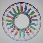
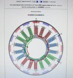
Yes, it's a 21/26. Since it's included in the calculators options, I have to assume that it's viable. They
will tell you if any combination's are unusable.

IMG_1821 (2) copy.jpg


It's not a common pattern, but will work none the less. I chose it, after a redesign from a larger pole
count, which left the motor with weak slots, or, not enough material for strength.
(discussion earlier in the build)

Unfortunately, it has an odd wiring pattern on the coils, which I think might be causing most of the problem.
But I could be wrong about that.

I like the idea of a no frills basic controller system of some sort, that would override all protocols, and
just make it spin, wether it overheats or not. This may well be a finicky controller issue.
I don't think were quite there yet, but it's always a good idea to discuss it, and make plans.

I'm working on a redesign for the stator plates when I make them out of glass board. One that doesn't use
set screws, but 'cups' them on both sides. At that point, I can choose another slot and pole count, one thats
a lot more common.
 
Good news and bad news.

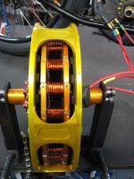
I got all the slots cut, and put it back together,.. the difference was night and day when I spun it by hand!
Gone was the hard turning motor of old.

My apologies to all of you that have been suggesting this all a long! I still can't believe that it makes 'that'
much difference. So thats one more big problem solved, and another step forward. :thumb: Thanks!
I'll try not to be so stubborn.

Slots cut.jpg


Unfortunately it's not enough. After hooking up to the power again, it still slowly cogs in one direction or
the other, depending on the phase wire connections. But it's a bit more lively this time at least, it's definitely
trying to go.

I did another phase output test on it, and got a higher reading than before, between .80v and .90v. So things
are looking better there.

Then I hooked up another Crystalyte motor that I have, to see what kind of phase output that has, and that was
when the bombshell dropped,.. it produce's 35v per phase! (300rpm)

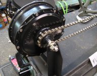
Crystalyte Phase output.jpg


Clearly this is the crux of the problem,.. the motor is vastly under par with phase volts.

But it's actually a good thing, because now we have something to concentrate on. Why do I have such a low
output? The only things I can think of at the moment is the wiring pattern, and the fact that the single coils
aren't producing the voltage thats needed.
So, I should go back to working on 'single coil' output, as they should be making some 3-4v each or more,
in order to get into the 30v range.
 
APL said:
I did another phase output test on it, and got a higher reading than before, between .80v and .90v. So things
are looking better there.

Then I hooked up another Crystalyte motor that I have, to see what kind of phase output that has, and that was
when the bombshell dropped,.. it produce's 35v per phase! (300rpm)
OK, so that means the kV of the motor you've made is something like 0.026 of the Crystalyte. 2.6% if my brain is working (no guarantees).

AFAICR, the more turns of wire, the higher the kV, all else the same. So you'd need something like 45 times the number of turns you already have on there to get the same voltage. I don't think that should be necessary to get what you're after, so something else must be wrong.

Even given that the number of magnets you have is around half what the Crystalyte has, while the number of poles is similar to the Crystalyte, it wouldn't account for that much difference.

Maybe the airgap between coils and magnets, or the width of the coils vs the width of the magnetic fields the coils output.

Since the coils are wired in series, perhaps the coils are not all wired in the right polarity, so some are cancelling out the voltage of others? (I think you eliminated that already, but bringing it up just in case)

Maybe the metal plates (that were just slit to fix the eddy current problem) are interfering wiht the field that needs to cut thru the coils?

Unfortunately I don't know enough to really be of much help to you figuring out where this particular problem lies. :(
 
On to rev2 motor :thumb:
Jokes aside, keep it up, you'll get it going!

If I average the coil outputs to .330v each, and multiply it times seven, for each phase set, I get an estimated 2.310v
at 280 rpm., which would seem to be an improvement over the last test I did, at the end page 13.

I think all coils of two phases create voltage as thats how motor is connected during use.
Your old kV would be 280/(14*0.33)=61 which is not unreasonable if the flux or turns are low.
Your new kV would be less than half: 25, if it's 300rpm/(14coils*0.85v)

It's a massive change, seems off if you didn't change anything except cutting the slots. Is it the same coil connections between these two tests?

Are you getting 7x each coil output measured on the star connection and 14x coil output on the phase-phase connection?
(Assumption is that all coils are wired in series)

If you're getting above voltage then i'd guess the alu plates were (and still are) creating eddy current and opposing fields, effectively reducing your airgap flux. It would heat up if this is the case.

How much current are you using from the ESC?
 
My first video, hope it works. :)

Gave it a couple of shoves, to show how free it spins, and then gave it the throttle a few times.

https://www.youtube.com/watch?v=4s-Ga9KiZY4&feature=youtu.be
 
amberwolf said:
AFAICR, the more turns of wire, the higher the kV, all else the same.
no, actually the more turns of wire, the lower kV.

Maybe the metal plates (that were just slit to fix the eddy current problem) are interfering wiht the field that needs to cut thru the coils?

Unfortunately I don't know enough to really be of much help to you figuring out where this particular problem lies. :(
i am also not an motor expert but afaik the problem is in that metal plates. if you imagine axial flux ac induction motor the rotor will be very similar to those plates. so my point is that aluminium plates which support the coils are the problem. the experiment with measuring phase voltage proofs it - the plates 'steal' energy from spinning magnets and output voltage is too low. it is very inefficient system. he needs to change beautiful anodized alu plates to some dielectric ones.
 
larsb said:
If you're getting above voltage then i'd guess the alu plates were (and still are) creating eddy current and opposing fields, effectively reducing your airgap flux. It would heat up if this is the case.
exactly! i beleive those plates are hot.
 
APL said:
I did another phase output test on it, and got a higher reading than before, between .80v and .90v. So things
are looking better there.

Then I hooked up another Crystalyte motor that I have, to see what kind of phase output that has, and that was
when the bombshell dropped,.. it produce's 35v per phase! (300rpm)

Did you spin BOTH at 300RPM?

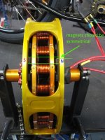
I noticed that your rotor (the magnets) are slighlty out of alignment (asymtrical) which will make it worse, but probably won't be the reason why it does not spin.
Did you make sure that there is everything ok with the polarity? It must be one N and one S per coil.


Slots cut.jpg
 
Hi,

Cutting the main plates with slots as you did was a first good step for removing the main eddy current loop, but there will still be some micro eddy current loops generated all around the coils as long as there is conductive material in the surrounding variable magnetic field. Even with the slots you made, the efficiency will stay low I think...
 
larsb said:
Are you getting 7x each coil output measured on the star connection and 14x coil output on the phase-phase connection?
(Assumption is that all coils are wired in series)

How much current are you using from the ESC?
I think this is important to rule out any connection issues, did you measure it?
In the video it looked like it went backwards in some locations and that would indicate a backwards coil connection somewhere.

You can try coils on the bench with a compass if you power it up on low current
 
You are right larsb, about the 7 vs 14 coil output. My mistake,.. it's 14 coils per phase output. That makes
me feel a little bit better, as I would only need a few volts from each coil to get towards the 30v output range.

I'll have to do another single coil output test with the cut plates, and see where it is now. If I can somehow
get it into the 2v range, I think we would be in business. 2x14=28v should harvest some results.

I'm giving it about half throttle from the ESC, but it will do the same thing at a lower throttle, or full throttle.
At half throttle the coils will start to get fairly hot in a few minutes. It definitely seems like it's fighting itself.
I attribute the heat to the motor not spinning freely in one direction.

The same speed for both motors on the KV test.

As madin88 pointed out, there are some PM's a little off the mark,.. the second bonding didn't quite match
up with the first. Another reason for redoing the back irons/pole count. The first try is the worst try.
But it should only reduce the motors efficiency by a few percent.
I did make sure that the polarity of the PM's is correct, and that the two sides are opposite of each other,
one side 'N' and the other side 'S'. I've checked that many times.
Then theres also the fact that it does the same thing with only one rotor being used.

I also spent a LOT of time making dang sure that the coils are wired up correctly according to the calculator.
I didn't, however, do an electrical test with the compass, to confirm.
I can do that next, as it is important to eliminate the possibility of a wiring issue. You are right. :thumb:

Hope I'm not being stubborn again, but I'm inclined to think that having cut the plates has eliminated 'most'
of the aluminum/eddy problems for the moment, at least enough to let the motor spin a limited number
of rpm's in one direction. The project is definitely going to get nonferrous plates soon enough, but in the
mean time, I think that the KV needs all the attention.

Aside from a mis-wiring job, the non-KV output indicates that the PM/coil arrangement is simply not doing
the job. Single coils work, but in unison they do not. And I'm inclined to try a ABC,ABC, wiring pattern.
It might tell us something, it might not, but it would be easy enough to do,..at least before the motor gets
torn completely apart again.

All in all, I think were getting close. Sooooo close.

I'm glad that the video is working, thanks for letting me know,.. one video is worth a million words. :)
I just noticed the Youtube box in the reply set up. I'm hoping that will bring up the Youtube thumbnail.
All new to me.
 
It's still not clear for me what the output is but i reread your posts. did you get 0.8v phase-phase at 300rpm? It's a normal kV but totally wrong vs the single coil output you had.

If you get 7x at the star &14x times phase to phase of one coil voltage when spinning motor then your connections are ok, otherwise NOK. Any discrepancy between these two measurements would give some input to where it is if done on all phases.

Measurement for the single coil should be done in completely assembled state of motor for voltages to match up - you might need some extension wires from the measured coil. Compass test is secondary, only needed if above test is NOK.

I had a thought on your video:
sensorless position sensing is difficult for your controller at really low rpm like in the video.
The BEMF measurement it uses can easily be disturbed and i wonder if a single coil backwards on one phase might do this.
Just as a test, can you adjust timing on controller? Might be worth to play with just to get it to turn a little more.
 
APL said:
I'm glad that the video is working, thanks for letting me know,.. one video is worth a million words. :)
I just noticed the Youtube box in the reply set up. I'm hoping that will bring up the Youtube thumbnail.
All new to me.

The Youtube box puts the videos inline with your posting. Use like this:

Code:
[youtube]4s-Ga9KiZY4[/youtube]

Note that you don't use the entire URL, just the "code" after the last slash in the URL. Use the YouTube share button to copy a nice clean URL that makes it easy to extract the code.

[youtube]4s-Ga9KiZY4[/youtube]
 
damirsky said:
amberwolf said:
AFAICR, the more turns of wire, the higher the kV, all else the same.
no, actually the more turns of wire, the lower kV.
Sorry, I get that mixed up sometimes. :oops:
 
Ahhh, thank you wturber, thats what I was looking for,.. and thanks for loading it up! :thumb:
Took me half a day just to wrestle it in there in the first place,.. this PC stuff gives me
an instant headache. :cry:

Larsb, I got roughly .8v for one phase, or 14 coils at 300rpm. YB .79v GB .78v YG .91v
One phase always seems to get a little more volt.

So that just seems plain wrong to me. Not even one volt for 14 coils! If a 14 coil set is in series,
even at .5v for each coil, I should get 7 volts a phase. 1v=14v and 2v=28v. Right?

I would think that 2v per coil at 28v per phase would be on par with the Crystalyte unit that
I measured. Although, it is a smaller motor, and I don't know what it has inside for poles.
So maybe I shouldn't be using that for an example too much. But if a motor is being used for
regen. it has to at least have that kind of output?

Yes, the sensorless positioning could be one major problem all right. I would think that spinning
the motor faster by hand while the throttle is opened would help with that, but when I do that,
it instantly 'insist's' on resorting back to what it's doing, and it seems to have no affect.
Not that it means a lot.
I'm not aware of any timing adjustments on the controller, if theres a way, then by all means,
I'd be happy to try it. Maybe it will make all the difference.

At any rate, the next step, I would think, is to get the compass conformation of coil alignments,
and a few single coil voltages in 'as is' arrangement.

Time for a little surgery, I'm sure glad this thing is easy to take apart!
 
Happy to see this motor spinning and the project continuing to go forth.

If you ever decide to build something that fits into a standard 135mm bike axle, and has either an efficiency, power density, or both advantage over ye olde radial flux design, consider me one of your first customers.
 
You bet neptronix! In fact, the next version should be built as a hub motor. Try as I may, I can't convince
folks that a mid-drive is the only way to go. Oh well, to each his own,.. there would be a lot more interest
as a Hubbie.

If I do get that far, and one gets made, I'll send it off to you and you can give it a good beating! We would all
love to see it getting whooped on,..er,.. I mean 'tested'. :)

But I'm getting ahead of myself, this project is far from over yet.

Thats it larsb, something very fishy going on, which is why I keep looking at that odd wiring pattern, and the
reversing poles,.. never did like it. Who could figure that out? Give me a nice series ABC wire job, with
all the coils positioned the same, and I'm a lot more comfortable. It probably won't run perfectly balanced,
but at this point, I don't really care. All the little screw ups are adding up on this motor anyway, and a new
pole count design will fix it.

But, we'll stick with the plan, and do the test's, and go from there. One thing I do know, is that it's all going
to be my fault!!

I must have something seriously messed up. But I've been over it and through it.
Well,.. the test will show,.. I'll try to get to it tomorrow.
 
I had another thought about the lower voltage--your magnets are relatively narrow and spaced relatively far apart; I wonder if this is lowering the total voltage somewhat because there is less time for them to induce current in the coils as they pass?

APL said:
I would think that 2v per coil at 28v per phase would be on par with the Crystalyte unit that
I measured. Although, it is a smaller motor, and I don't know what it has inside for poles.
IIRC, most of these typical DD hubmotors are 23 pole pairs (46 magnets), and I think it's 51 coils (17 per phase).


Some, like the old X5304/etc series I think had much larger magnets, something like 12 pole pairs (24 magnets) (I forget the number of coils), which is similar to the Stromer Mountain33 Ultramotor I've got here, which has 16 magnets, so 8 pole pairs, and 18 coils (6 per phase).


IIRC, the backiron is always thicker the fewer / wider magnets there are, so the motor gets heavier than on a higher pole count motor, which can have a thinner backiron. (look around at pics of various pole-count hubmotors and you can see what I mean).
 
If you're going to rebuild the motor, you might consider a different pole configuration. There are many that can work.
My old BMC motor (the one in my avatar) had 16 stator poles and 18 magnet poles. The stator poles were "concentrated winding" where 3 teeth in a row were on the same wind (in series). I always thought it was a strange setup but it worked well.
 
APL said:
You bet neptronix! In fact, the next version should be built as a hub motor. Try as I may, I can't convince
folks that a mid-drive is the only way to go. Oh well, to each his own,.. there would be a lot more interest
as a Hubbie.

If I do get that far, and one gets made, I'll send it off to you and you can give it a good beating! We would all
love to see it getting whooped on,..er,.. I mean 'tested'. :)

That would be a real honor!
I think that a small size axial flux motor that's happy to spin at 1500 - 2000 RPM so that you could run an easy single reduction to the rear would be the most exciting thing i've seen on this forum since i joined.

Of course a hub is more likely to be mounted and running... :mrgreen:

APL said:
But, we'll stick with the plan, and do the test's, and go from there. One thing I do know, is that it's all going to be my fault!!

This reminds me of where i'm at with my recumbent build. I'm out in the woods with no guide, except for random posts on bentrideronline etc, which apply to bikes like mine, but never my specific bike, which is even weirder than most recumbents. No bike shop has any experience with recumbents; the best local one throws their hands in the air the second i walk in the door :lol:. It's been up to me to learn a lot of things from scratch about fabrication and mechanical engineering. I've had to reverse engineer a lot of things.

The process is 500% more painstaking, defeating, and time consuming than any ebike build i've done so far. The only thing keeping me going is that i know there's a very juicy result at the end.

It reminds me of the process you are going through. How many people on this forum have built axial flux motors? ... yeah, i thought so. :lol: you get to be the pioneer and teach everyone. I wish you the best.
 
Thanks for the info. amberwolf, I know that the H35/40 series Cryt. has 51 coils, but I was never quite sure about the
pole pairs. I put my motor back together, and only have photos, and can't make it out. Not that it maters all that much
at the moment, I'm only using it as a rough guide.
Strangely, I have never been able to find a stator wire diagram for one, so I still don't know how it's coils are wired.
A hundred pages on the Sphere, and all the internet info, plus the company itself. Nada.

Well, we have the motor calculator, which has saved this project, so it's all good.

Thinking about your comment on magnet size and spacing,.. you may be right. I'm thinking that a faster spin would
compensate? Hmmm, I know that the wind generators guys use this kind of arrangement fairly often, and they
seem to get good voltage out. They often have some pretty good (wide) spacing as well.
I suppose I shouldn't lean to heavy on their builds,.. they are even cheaper than me sometimes, and probably
know even less about it. :lol:

Fechter, when I rebuild the stator with nonferrous material, we will have to look take a good look at a suitable pole
configuration. I would like to keep the same cores, since they were so hard to make, if possible. And I'd need a
number that 'fills in' the stator size that this motor has. Not to few and not to many.
If I rebuild the motor completely, V2, I can change the core shape and size, and go with a much lower pole count.
Anything goes at that point, whatever we think is the best configuration, and size motor. That will be a new post.

But I did look up your BMC motor on the calculator, (I think it's the one), and see the three tooth pattern. Seems
like it might be a higher torque motor that way? I do like the winding factor!

Bavaria:http://bavaria-direct.co.za/scheme/calculator/

IMG_1962 (1) copy.jpg


Thanks Nep, and your right, keep your eyes set on the end product,.. only the ones that don't give up, get there!
 
Back
Top