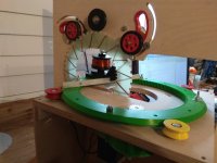
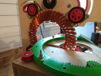
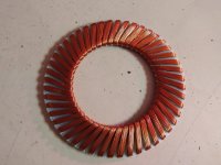
APL's DIY axial-flux motor

I've been trying to get some power readings for the current Crystalyte set up on the Cruiser I'm ridding
now,.. to be compared with the Axial Del Oro motor once I have it installed.

Trying to find a windless day has been difficult though, so for the moment, I have to average a bit.
Readings are all in the same first gear.

Some preliminary readings are; 75 - 90 watts with wind on the flats. 110 - 135w into wind. 21mph. spd.
Not a strong wind. (10-12mph?)

On a quarter mile average country hill, it will drop down to 18mph, and use about 230w.
If I floor it at full throttle, it will spike at about 500w.

So that will at least give me something to compare the axial with,.. for what it's worth. Now I can switch
the two motors around and see what happens.

After that, I think I'm going to get another $30. spool of copper, and double the windings, just to see where
that leads.
Then, it's time for a complete tear down. I'll order up some Garolite, for the new composite plates, and
get started on making them. Plus, it will give me a chance to fix the axle, and give 'ol' lumpy' a nice
straight spin. :thumb:
 
I wonder if anybody nearby has a cycle trainer you could hook up to. Either that, or a cheap on on Craigslist. Then you could have a standard of comparison that would be pretty constant.

https://www.amazon.com/Sportneer-Trainer-Exercise-Magnetic-Reduction/dp/B07SST83B8/ref=pd_lpo_sbs_468_t_1?_encoding=UTF8&refRID=0FS7DPF75R4E52H44R5R
 
Good idea wturber, I have a cheaper trainer, but haven't looked at it in a while. :oops: I'm not sure if it
will work on the cruiser, but it's worth a try, and it would give more consistent readings.

I'm pretty sure the Axial is going to be so out of place, that the comparison between the two won't be even close,
but you never know. I'll give it a try,.. I've been surprised before.
Mostly, I just want to feel it yank'n me down the road! :D
 
As I was saying before, when I redo the stator plates, I have the option of going with another pole count
design, as long as it is similar to the one I have now. I can't get too far away from this number without
making new, bigger, cores.

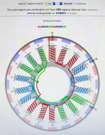
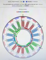
So the current contenders are an 18/20 slot-pole count, with a .945 winding factor, and a 180 cog steps.

IMG_1971 copy.jpg

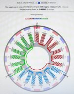
A 21/20 S/P, with a .953 winding factor, and 420 cog steps.

IMG_1972 copy.jpg

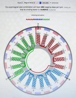
Or a 21/22, with a .953 winding factor and 462 cog steps.

IMG_1973 copy.jpg

Taken from Bavaria motor calculator; http://bavaria-direct.co.za/scheme/calculator/

It will also give me a chance to redo the back iron's and PM magnets, with slightly larger/wider magnets,
(more overhang), and a more perfect distribution. ( I didn't do that great of a job on the ones I have.)

Any advantage to having more or less cogging steps?
(currently, I have a 21/26, .846 WF, 546 CS.)
 
When building a motor from scratch i think that it would be helpful to have a simulation of the magnetic circuit. I know about a tool which is called EMETOR which has often been used here in ES to check a given motor, or a complete new design.
Search for member "Miles" and you will find lots of stuff about it.
For EMETOR you need an account which is not for free from what i know, but maybe he or someone else here can help you with it and do the simulations.

Aside from the slot and pole count there are MANY other important things, like magnet coverage, airgap width, magnet strength, shape of stator core, slot opening etc etc.
The shape of stator core and magnet coverage have influence on BEMF, which would be nice to have it quasi sinewave.
Airgap width and magnet strength + thickness have influence on max RPM and torque.

From my side i can say that 18N16P would be a good candidat for a sinewave BEMF. That was mentioned in a paper i read about motor design, and many geared e-bike motors or RC Motors have 18N16P / 20P so this would be my first choice too.

Keep on the good work :thumb:
 
IMG_1971%20copy.jpg

I would use this one. Reason being that the stator sees pure rotational force from each winding. If the green phase is active you get two torque vectors on opposite sides of the stator and no net displacement force. The two other ones, when only one phase is active, produce only one torque vector so the stator has to provide equal but opposite force (rotational and displacement)... This equal but opposite force may cause noise and vibrations ?
 
Yes, it seem's we are always in school on motor tech., and I don't think theres any graduation ceremony either.
I'm amazed at how something so simple, (two parts), can involve all the sciences, math, physics, electronics,
chemistry, mechanics, magnetic flux, etc.,.. in such a heavy, non-understandable, way.

The blog I'm chewing on at the moment is a pretty good one, and keeps it fairly simple. (Just the way I like it :) )
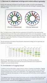
It touches on the pole count, balance thing more than most, and is worth a look. Relevant's to our discussion are
found at the bottom of the article.


IMG_1974 copy.jpg

Taken from 'Things In Motion' ; https://things-in-motion.blogspot.com/2019/


Anyway, he confirms that the 21/20 & 21/22 combos are not balanced very well, as Lebowski has just said. And
I have read in a few other places, that the combo's will work, but with uneven issues. Now I know why.

So it seems that the 18/20 takes the lead. It will make the motor lighter, having 3 cores and 12 magnets less, plus
give it a stronger stator, with more room between the teeth, and more space between the PM magnets, for what
thats worth. I'd like to use 13mm wide PM's for a little (1.5mm) overhang on each side of the tooth anyway.

But madin88 is right, the motor needs to be completely redesigned, taking in to account all the important stuff,
like, geometry, tooth profile, spacing, and shapes. I'm just trying to make this one better, before it gets shelved.
 
Cheers for the info, this thread is turning into a seriously useful resource for anyone interested in building their own motor :bigthumb:

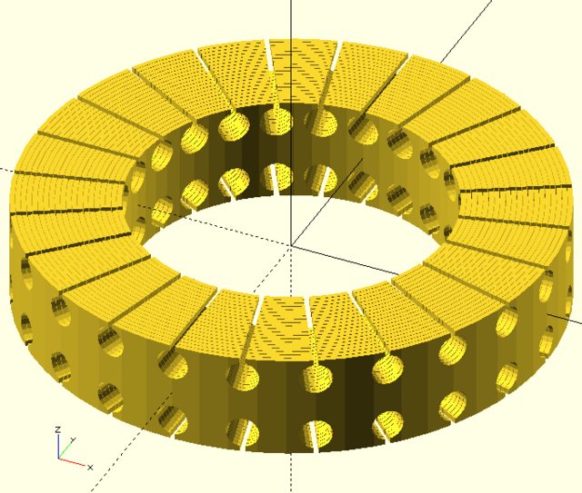
Another thought on a roll of strip as laminations. So individual rolls wont work (the blog linked above also has some diagrams relating to why in the most recent post) but one big roll looks like it would and would be easy to drill and slot for windings and one done that way could work for either windings on the poles or between them (or maybe both?).

DQItNbyl.png


(EDIT: Yay, first time posting an image :) That was drawn in openSCAD using a parametric model, very slow as-is but could easily be slimmed down so different counts and dimensions could be quickly visualised, can upload it or just post it here if it's any use).
 
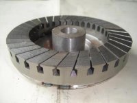
Not a bad idea. I've seen some similar designs using a big roll of iron. Drilling might be a bit challenging and might short the laminations around the holes. In practice, these kinds of shorts don't seem to create large losses because they are very thin.

Axial Flux Stator2.jpg
 
fechter said:
Not a bad idea. I've seen some similar designs using a big roll of iron. Drilling might be a bit challenging and might short the laminations around the holes. In practice, these kinds of shorts don't seem to create large losses because they are very thin.

Axial Flux Stator2.jpg

Yeah, seemed like a fairly simple layout, the idea was to roll around a lump of hardwood turned to the correct ID so the laminations don't bend when drilling through and cutting the slots. Could screw 2 pieces of wood together at an angle so they come out easily or just drill/break a single piece out for a one off.

Do you have a link to the one in the photo you posted? Interested in how the rotor is done, I'm looking into a coreless motor with a field wound rotor, a thin disc with the windings running at pretty much the same angle as the slots in that pic. Not sure if it will work though, aiming at something lightweight and 3d printable but just back of the envelope stuff for the mo, still have to get to grips with magnetic field simulation software.
 
fechter said:
Not a bad idea. I've seen some similar designs using a big roll of iron. Drilling might be a bit challenging and might short the laminations around the holes. In practice, these kinds of shorts don't seem to create large losses because they are very thin.

So would running a rotating wire brush or small diameter honing tool down each drilled hole clean up those shorts?
 
I like the idea as well. Lamination material comes in rolls from the manufacture, and you can have it cut
to most any width you want, so it's a natural for that. I hadn't thought of drilling or milling holes though,
better than slicing, and definitely DIY-able. Great idea. :thumb:
Probably have to go back to multi strand wire, but it would be worth it to have easy stator construction.

Perhaps we could try one in reality, by using something other than lamination material,(plastic?), just to get
a grip on how it would go. :?:

Wturber beat me to it, but I was just going to say the same thing,.. that reaming, sanding, grinding, the
inside of the holes will probably de-bure the laminations. Also might be able to unwind it, re-coat it, and
roll it back up? (probably not)

Drilling a few extra 'small' holes in the middle for mounting it to the axle flange is a big plus too. And both
surfaces would be naturally perfectly aligned, and solid,.. another plus.

Oh boy! I get to bring back the automatic Lam. notcher video! :) All you need is a million dollar machine!

Lamination notcher video; https://www.youtube.com/watch?v=XgUky1jUOW0
 
Sand blasting or vibratory polishing should clean up machined surfaces ok. Sand blasting should be an easy one to source but it's likely to spread the laminations (get embedded between them). Vibratory polishing would be a bit harder to source but wouldn't cost a whole lot to get set up with and would come in useful for all sorts of deburing (vibratory unit and a truck tire screwed down to a spring mounted board). I made a small one up a few years back and it worked well, would have worked great with the right abrasive media.
 
stan.distortion said:
Do you have a link to the one in the photo you posted?

http://www.jystator.com/axialfuxstator.html

Here is a whole page of ideas. I like using Google image search for brainstorming:
https://www.google.com/search?q=axi...KDQIHaL5DcEQ_AUIESgB&biw=1366&bih=604#imgrc=_
Some interesting coreless designs as well.

I really don't know how much the burr from milling or drilling slots would affect the lamination losses. I know it's bad, but not sure how bad. It might be so minor it's not worth sweating over it.
 
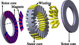
I see a few toroidal wound axial stators, and it seems an attractive way to do it, because winding the coils
would be much easier. But I have a hard time figuring out which coil activates which teeth?

2-Figure1-1.png

Do both sides of the stator become north, and the next set of teeth become south on both sides? I suppose
the rotor PM's are N-N, S-S, straight across from each other then.

Also, I think every other coil has to be reversed, in order to do that, making an ABC,ABC, winding only motor. :?:


Taken from: https://www.semanticscholar.org/paper/Analysis-of-a-Dual-Rotor%2C-Toroidal-Winding%2C-Vernier-Zou-Li/e0954acb704a4275f81a83c4e96a67c651f32d25
 
I'm looking into a coreless motor with a field wound rotor, a thin disc with the windings running at pretty much the same angle as the slots in that pic. Not sure if it will work though, aiming at something lightweight and 3d printable but just back of the envelope stuff for the mo, still have to get to grips with magnetic field simulation software.

I started playing with a similar idea two years ago, but the project is on hold right now for different reasons. The idea is very similar to what this guy did : http://build-its-inprogress.blogspot.com/2015/02/coreless-axial-flux-motors.html

I coiled 3 phases. each consist of 9 complete turns of 5 parallel awg#20 wires around a machined 10" diameter FR4 disc with a homemade automated coiling machine equipped with step motors, laser sensors, raspPI+slushengine programmable stepper board

First coil phase on the coiling machine:
coil beginning crop.jpg

Winding the third phase:
coil end.jpg

Final coil result:
final result crop.jpg

Small video showing the coiling process:
[youtube]Ujc41BGiGiQ[/youtube]
 
Your coil winding machine is one of the most impressive things I've seen yet ENNOID! Looks like a massive amount
of effort, and the stator is turning out great. I hope you pick the project back up someday soon,.. it's just the kind of
build we like to see, and it's off to an awesome start! :thumb:
 
Thanks APL.

I will give another try to my design during next winter. Even with the coiling machine, it takes a while to coil everything, something like 12 hours with all wire loading. For now, it is good enough for testing. There is a way to improve the coiling speed x5 with the actual coiling machine and probably more with better hardware.

I created a mold and been able to mold everything into polyester resin for an inrunner motor config. I haven't taken any picture of those steps. sorry. The final diameter of the stator part is now 12" with the molded shoulder for attaching the other parts. Rotor with magnet is similar to your design I think, but I also want to try a reluctance rotor without magnets (just plain steel with dents), but I'm still not there yet. I don't have an appropriate motor drive for such a special arrangement...
 
I like the size! I'm very curious as to how much power it will wind up having. That particular stator design is
just so perfect, and should make the lightest possible axial motor. If it has the power to move a bike around,
I'm going to drop everything, and go in that direction! :thumb:

Is this motor going on a bike, or do you have other plans for it?
I imagine it has a high RPM range.
 
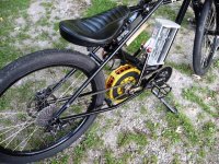
Today was a good day for the golden lady, I finally bolted her in the bike, and made some quick phase connection's.
It wasn't easy,.. I had to mill the axle faces down, to fit in the dropouts, re-tap and countersink the bolts, and grind
the inside of the BB cup/adaptor to fit over the drive side axle. Plus take the old Crystalyte out.

But now it's done, and it's time to hit the road at long last. :D I was beginning to wonder if this moment would ever come.


Motors in!.jpg


It was getting late tonight, and unfortunately, the batteries were almost dead, but I couldn't help taking it out for a
quick test anyway.

As we knew already, she's a high rev'er, and even though I have it in the lowest gear, and have a 17T cog on the motor,
instead of the 20T on the Cryt., it struggles a bit to get going. Drawing about 450w. However, once it gets up to speed,
it quiets up, and draws about the same as the Crystalyte does! So it's promising.

It's sure nice to be flying down the road! And tomorrow I'll have the batteries all charged up for a decent day of testing.
I'll get all the watt/speed measurements, as well as the temperature's :bolt: :bolt: :bolt:
 
fechter said:
i've wrote a message to them and they sent me a quotation.
tooling cost: $3000 (this is stamping machine cost)
sample fee: $100 per each
for the mass production (at least 500 pcs and pay for tooling $3k) they charge about $45 per piece for 0.2 mm laminations and about $30-$35 for 0.35 mm laminations.
for sample cutted by EDM the price is around $800-$900 per piece.
all these prices are provided for small stator core with size: internal diameter 24 mm, external diameter 100 mm, height 32 mm, 12 theeths.
 
ENNOID said:
I'm looking into a coreless motor with a field wound rotor, a thin disc with the windings running at pretty much the same angle as the slots in that pic. Not sure if it will work though, aiming at something lightweight and 3d printable but just back of the envelope stuff for the mo, still have to get to grips with magnetic field simulation software.

I started playing with a similar idea two years ago, but the project is on hold right now for different reasons. The idea is very similar to what this guy did : http://build-its-inprogress.blogspot.com/2015/02/coreless-axial-flux-motors.html

I coiled 3 phases. each consist of 9 complete turns of 5 parallel awg#20 wires around a machined 10" diameter FR4 disc with a homemade automated coiling machine equipped with step motors, laser sensors, raspPI+slushengine programmable stepper board

First coil phase on the coiling machine:
coil beginning crop.jpg

Winding the third phase:
coil end.jpg

Final coil result:
final result crop.jpg

Small video showing the coiling process:
[youtube]Ujc41BGiGiQ[/youtube]

Your winding machine is seriously impressive! Yeah, same layout but with the same again on the rotor, field windings instead of magnets. Even the same blog as inspiration but originated from pics of an EV project by Lucas (UK) in the 1970s. Planning on running the field windings parallel with the stator windings (wound the opposite way on the rotor disc), not sure how that will work out, really need to figure out all the maths involved but might get a chance to print something simple out just to give it a try over the next few days.

Congrats on the first test ride APL, looking forward to hearing how it goes on a full charge :) :bigthumb:
 
Took it out today for some test riding, and was able to get some readings, but also ran into a problem with
the stator cores and PM's grinding against each other at high speed/power. At least I think that's what it is.

In first gear drew around 180 - 200w at 21mph. No acceleration on the flat. 78 deg. end temp.
Same gear it drew 195 - 215 at 27mph. 87 deg. once it leveled out. (27mph in first! :lol:)
Maybe I can make a 'salt flats' racer out of it.

Second gear, which is what I used with the Crystalyte exclusively, it was 195 - 215 at 21mph.
And at 29mph. it drew around 400w, and was getting hotter, at 100+ deg.

Keep in mind that the watts and temp's are all over the board depending on the moment or spot, so it's a
bit averaged here and there.

The highest temp. was after a two mile ride at full throttle, and was about 140 deg. on the copper winds,
and around 200 or so on the stator plates. I think the plates are still drawing extra heat, like larsb said.

The motor is still unadjusted or aligned as far as the cores and air gap is concerned, so more efficiency is
to be expected from doing that, plus the wobbly rotors don't help at all.

The grinding sound comes on at around 400 watts and 27mph.,.. and suddenly, like it has a threshold where
something gives. The cores might be coming loose, or the stator 'fingers' that we cut may be bending side-
ways, but it needs to be taken apart, looked at, and adjusted.

Since the next step is to double up on the windings, I'll just wait till then. It's obvious that the motor wants
to spin too fast, and twice the wind's should half the speed. And hopefully, let it run cooler at the same time.

I tried to get a video of it in action, but the batt's were getting low again, and trying to ride and hold an I-pad
steady, is a learning experience. So I'll try again tomorrow. The vid's that I got today are just to crappy.

All in all, it was a good day, and I'm pretty happy with the figures,.. and a few problems are to be expected
on a new build. :thumb:
 
Back
Top